C100 Series - Automatic PF Correction Assembly - Gentec
C100 Series - Automatic PF Correction Assembly - Gentec
C100 Series - Automatic PF Correction Assembly - Gentec

You also want an ePaper? Increase the reach of your titles
YUMPU automatically turns print PDFs into web optimized ePapers that Google loves.
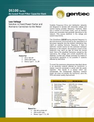
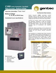
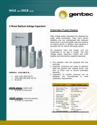
<strong>C100</strong> series<br />
<strong>Automatic</strong> Power Factor <strong>Correction</strong><br />
<strong>Automatic</strong> Capacior Bank <strong>Assembly</strong><br />
The Reactive Power Solution<br />
4, 6 Unit Assemblies<br />
‣ 10 to 600 kVAR<br />
‣ 208 to 600 Volts<br />
‣ Nema : Type 1 & 12<br />
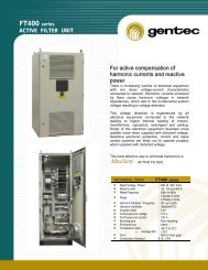
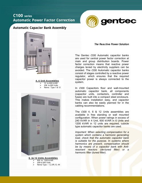
The <strong>Gentec</strong> <strong>C100</strong> <strong>Automatic</strong> capacitor banks<br />
are used for central power factor correction at<br />
main and group distribution boards. Power<br />
factor correction means that reactive power<br />
charges levied by electricity suppliers can be<br />
avoided. The <strong>C100</strong> <strong>Automatic</strong> capacitor banks<br />
consist of stages controlled by a reactive power<br />
regulator, which ensures that the required<br />
capacitor power is always connected to the<br />
system.<br />
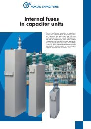
In <strong>C100</strong> Capacitors floor and wall-mounted<br />
automatic capacitor bank, all components<br />
(capacitor units, contactors, controller and<br />
fuses) are built into a compact steel enclosure.<br />
This makes installation easy, and capacitor<br />
banks can also be easily planned for in the<br />
cabling recommendations.<br />
The <strong>C100</strong> 4, 6 & 12 Units assemblies are<br />
available in free standing or wall mounted<br />
configuration. When power ratings in excess of<br />
240 kVAR in 4 Unit, 600 kVAR in 6 Units and<br />
1200 kVAR in 12 units are required, cubicle<br />
type automatic capacitor banks are used.<br />
Important: When selecting compensation for a<br />
system which contains a harmonic generating<br />
load, check that the automatic capacitor bank<br />
is suitable for the purpose. In systems where<br />
harmonics are present, compensation should<br />
be by means of a capacitor bank with Antiresonant<br />
reactors (de-tuned filter) or a<br />
harmonic filter (tuned filter).<br />
6 to 12 Units Assemblies<br />
‣ 400 to 1200 kVAR<br />
‣ 208 to 600 Volts<br />
‣ Nema Type – 1,2,3R,12, 4X
<strong>Automatic</strong>ally Switched<br />
50 to1200 kvar<br />
GENE<br />
RAL INFORMATION<br />
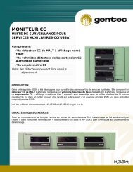
The indoor automatically switched Type <strong>C100</strong> Capacitor<br />
is a durable, self-supporting, steel structured assembly<br />
which permits automatic control of power factor<br />
correction. This field tested bank is UL and CSA<br />
Approved and meets the Electrical Code requirements for<br />
protection and safety of the customer and equipment.<br />
The <strong>C100</strong> banks are intended for indoor or outdoor<br />
applications on 240, 480 and 600 volts, 3 phase 3 or 4<br />
wire systems. Equipment is suitable for operation in<br />
ambient temperatures up to +40 degrees C. Type <strong>C100</strong><br />
banks incorporate the dry self-healing technology of the<br />
DSHI capacitor with the dependable switching service of<br />
the previous liquid filled equipment to provide the ultimate<br />
in power factor correction at an affordable price. The<br />
product value is further enhanced by competent support<br />
from the company representatives, who offer<br />
maintenance, initial operating instructions and explain to<br />
the user, the function of the bank features.<br />
THEOR<br />
Y OF<br />
OPERATION<br />
The automatic control system is designed to insert or<br />
remove kvar in predetermined steps as required by the<br />
load. Fluctuating loads are tracked using a current signal<br />
from a current transformer which monitors the total<br />
system load and a voltage signal from a potential<br />
transformer mounted in the capacitor bank. The<br />
controller continually monitors the reactive power being<br />
drawn from the utility system and automatically switches<br />
capacitors on or off as required. The automatic system<br />
prevents over-correction at light load conditions and<br />
supplies essential kvar as the load increases to reduce<br />
voltage drop and improve the power factor of the system.<br />
DESIGN<br />
FE<br />
ATURE<br />
Due to the absence of fluid, the new dry <strong>C100</strong> design is<br />
smaller and lighter and is supplied in more versatile<br />
enclosures than previous designs. Drip trays are now<br />
eliminated as there is no leakage hazard and capacitors<br />
are environmentally safe. The dry self-healing capacitor<br />
cells are packed in vermiculite insulation and housed in<br />
steel casings which results in a capacitor bank which<br />
offers virtually low fire hazard. Internals fuses isolate<br />
defectives cells.<br />
The UL and CSA approved <strong>C100</strong> banks are available in<br />
larger kvar ratings per enclosure than the previous<br />
designs, Steps are protected by 200 Ka HRC current<br />
limiting fusing and are equipped with current limiting<br />
devices to reduce inrush currents produced by back-toback<br />
switching. This gives longer life by supplying a bank<br />
that is less likely to fail. The increased kvar supplied in<br />
smaller enclosures reduces installation, shipping,<br />
handling and initial purchase price thereby providing<br />
substantial savings to the user.<br />
IN OPTION:<br />
A GFI 120 V. breaker can be supplied on all <strong>C100</strong> banks<br />
to provide high protection level again the person. This<br />
breaker would go out if the control source becomes short<br />
circuited.<br />
TECHNICAL DATA<br />
<strong>Automatic</strong> power factor control systems are designed to<br />
meet all UL and CSA requirements for power factor<br />
improvements in the average industrial plant. Equipment<br />
consists of a 4, 6, 12 unit metal enclosure which houses<br />
the required quantity of 3 phase capacitor units, fuses<br />
contactors, reactors, controller, control components and<br />
wiring.<br />
Housings : The <strong>C100</strong> bank enclosure is a 4, 6, 12 units<br />
free standing metal NEMA rated housing. The housing is<br />
supplied with vented doors to allow for ventilation and<br />
cooling of the control components. Banks which exceed<br />
the 4, 6, 12 unit limitations would have factory supplied<br />
control wiring between separate housings or can be<br />
supplied with individual power connections to each<br />
housing.<br />
Page 2 of 4
Power cables are connected to the cubicle at the upper<br />
right hand side. The income termination is made to two<br />
600 MCM solderless cable lugs provided on each phase.<br />
Fusing Protection :<br />
Cables feeding the <strong>C100</strong> capacitor bank must be<br />
protected by an over-current device as per Code<br />
regulations. The capacitor bank termination lugs are<br />
mounted on copper bus having an ampacity rating the<br />
same as or greater than that of the termination lugs. Lugs<br />
and bus are insulated from the housing by 600 volt standoff<br />
insulators. Current limiting type HRC fuses having a<br />
200,000 ampere fault interrupting capacity are provided<br />
on the bus prior to cable derating to protect the wiring to<br />
each phase of each each individual capacitor step. To<br />
provide additional protection the control circuitry is fused<br />
on both the primary and the secondary of the control<br />
transformer.<br />
Current limiting Devices :<br />
In an automatic switched bank, capacitors are installed in<br />
close proximity to each other. Without current damping<br />
devices between capacitors, the inrush currents created<br />
by back-to-back switching can cause undue stress on the<br />
capacitor dielectric and also contactor pitting leading to<br />
premature failure. All <strong>C100</strong> switched banks are provided<br />
with current damping device to smooth the initial high<br />
current spikes created by the switching operation. The<br />
addition of this damping device provides longer<br />
component life and less maintenance down time.<br />
Contactors :<br />
The contactors used in <strong>C100</strong> banks are specifically<br />
selected for capacitor switching duty providing durability<br />
and reliable switching. The contactors are sized base on<br />
the Kvar and voltage rating values.<br />
steel casing to provide a rugged durable product. The<br />
240, 480 and 600 volt DSHI capacitors have their cells<br />
internally connected in delta. The 750 volt construction<br />
design is internally wye connected.<br />
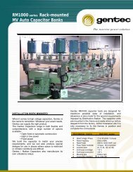
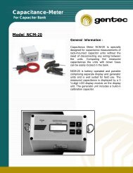
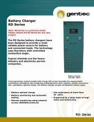
Controller :<br />
For this applications <strong>Gentec</strong> inc uses the Nokian N12 or<br />
NC12 capacitor controller. This controller regulates<br />
power factor correction by means of VAR sensing. As the<br />
power factor deviates from unity the reactive power is<br />
measured by means of a current transformer mounted on<br />
the line side of the system load and a potential<br />
transformer contained within the capacitor enclosure.<br />
Capacitor steps are added or subtracted as required.<br />
Care should be taken when selecting individual step sizes<br />
to avoid kvar ratings below the minimum switching level of<br />
the controller .<br />
The N12 or NC12 controller is available in 12 step<br />
designs. A target cos ∅ <strong>PF</strong> override is supplied to<br />
provide a means of maintaining the power factor over the<br />
range 0.90 to 0.85 lagging. The standard controller is<br />
provided with capacitive load, inductive load and step<br />
indicating lights. Adjustable CK settings are used to set<br />
calculated levels for addition or removal of capacitor<br />
steps.<br />
This controller is supplied with inductive load, capacitive<br />
load indication and step indication. Front Key board<br />
allows manual override to check individual capacitor<br />
steps. Step switching is provided with programmable,<br />
time delays for individual steps. In the event of a power<br />
failure (over 30 milli secs.) all connected steps are<br />
switched off by a built-in loss of voltage feature and<br />
reconnected step by step after a time delay.<br />
Capacitors : <strong>C100</strong> capacitor equipments use the dry<br />
self-healing type DSHI Capacitor as described for the<br />
individual kVAr steps. internally fused and are selfhealing.<br />
The dielectric consists of metalized<br />
polypropylene film. Cells are protected from moisture and<br />
foreign matter by thermosetting resin and a plastic case.<br />
Individual cells are packed in vermiculite and housed in a<br />
N6 - N12<br />
NC12<br />
Page 3 of 4
Control Transformer:<br />
A control transformer is mounted in the first group bank<br />
housing to provide sensing to the control circuit. This<br />
transformer is connected across "A" and "C" phases on<br />
the line termination bus to ensure proper phasing. The<br />
customer mounted current must be installed in the "B"<br />
phase or else proper phase rotation of the potential<br />
leads must be observed. The CT must be installed on<br />
the line side of the system load and voltage and current<br />
must be at same potential reference of the transformer.<br />
Capacitor assembly to monitor the total load current to<br />
be corrected.<br />
GENE<br />
RAL SPECIFICATION<br />
The automatically switched power factor correction<br />
system shall be type <strong>C100</strong> or approved equal suitable<br />
for use on a 600V (or 240, 480) 3 phase, 60 Hz, 3 wire<br />
(or 4 wire) system. It shall meet the requirements of<br />
current UL and CSA standards and the Electrical Code.<br />
The capacitor bank will be designed for indoor<br />
installation and for operation in ambient temperatures up<br />
to 40°C. Enclosures provided will be indoor or outdoor<br />
rated for floor mounting complete with proper ventilation<br />
and lockable doors. A means will be provided to quickly<br />
and easily replace faulty capacitor units in the field.<br />
The capacitor bank will be factory wired and assembled<br />
complete, ready for setting in place and connection to<br />
the power system and to the 2 wire signal from a<br />
remotely mounted current transformer.<br />
• Indicators for number of stages energized<br />
and the switching direction<br />
• loss of voltage element<br />
• six or twelve step switching with provision<br />
for steps to handle added kvar as the load<br />
grows.<br />
2. Contactor with current limiting device will be<br />
supplied in each step to limit inrush currents<br />
during switching operations.<br />
3. Fuses will be installed to protect the cable leads<br />
feeding each capacitor step.<br />
4. Switching shall be by means of contactors<br />
specifically rated for capacitor switching duty to<br />
ensure long life and trouble free performance.<br />
5. Bank operation shall be readily detected by<br />
means of LED display installed on the front of<br />
the housing on the controller.<br />
6. Capacitors will be the dry, self-healing type DSHI<br />
with no free fluid and extended foil construction<br />
to minimize losses and prevent loss of<br />
capacitance due to premature tab failure. Each<br />
capacitor will be fitted with discharge resistors to<br />
reduce the residual voltage to 50 volts crest in<br />
less than 1 min. from de-energizing. Units will<br />
be individual design to allow easy changeout.<br />
7. Direct heat transfer supplied on each internal<br />
cells fuses<br />
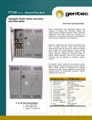
ORDERING INFORMATION<br />
The following information should be supplied at the order<br />
entry stage to ensure the most economical bank with the<br />
highest degree of correction is supplied :<br />
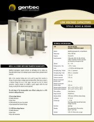
4 Unit <strong>Assembly</strong> 6 Unit <strong>Assembly</strong><br />
Wall mounting<br />
Floor mounting<br />
COMPONENTS<br />
1. Operation shall be by means of an electronic<br />
controller with the following features :<br />
• auto/manual control<br />
• variable operating time settings.<br />
1. Characteristics of the load to be corrected i.e. amps,<br />
voltage, power factor.<br />
2. KVA rating and percent impedance of the transformer<br />
supplying the load to be corrected.<br />
3. Special Filter Devices equipment on system e.g.<br />
D.C./ A.C. drives, variable freq. drives, etc.<br />
4. CT ratio to be confirmed..