Cyclone Manual - Tempest Lighting, Inc.
Cyclone Manual - Tempest Lighting, Inc.
Cyclone Manual - Tempest Lighting, Inc.

You also want an ePaper? Increase the reach of your titles
YUMPU automatically turns print PDFs into web optimized ePapers that Google loves.
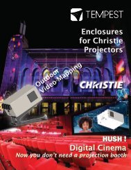
User <strong>Manual</strong> and Installation Guide<br />
User <strong>Manual</strong><br />
Tornado Moving Light Enclosures<br />
Heater Fan On Relay<br />
Temp<br />
DMX<br />
Lamp<br />
ESC<br />
<strong>Tempest</strong> <strong>Lighting</strong>, <strong>Inc</strong>.<br />
13110 Saticoy Street, Unit C<br />
N. Hollywood, CA 91605, USA<br />
OK<br />
For all <strong>Cyclone</strong> projector<br />
enclosures manufactured after<br />
June 2013<br />
Tel +1 818 787 8984<br />
Fax +1 818 982 5510<br />
info@tempestlighting.com<br />
www.tempest.org<br />
<strong>Inc</strong>luding <strong>Cyclone</strong> HUSH Enclosures<br />
In the interest of continuous product improvement, the information in this document is subject to change without<br />
notice. Neither <strong>Tempest</strong> <strong>Lighting</strong>, <strong>Inc</strong>. nor its representatives or agents may be held liable for expense or injury<br />
arising from it.<br />
© <strong>Tempest</strong> <strong>Lighting</strong> <strong>Inc</strong>. All Rights Reserved August, 2013<br />
<strong>Cyclone</strong> Enclosure User <strong>Manual</strong> page 1
Table of Contents<br />
1 Introduction .........................................................................................................5<br />
Dimensions, Weights and Projector Fit ........................................................6<br />
2 Installation ...........................................................................................................8<br />
Safety and Warnings .....................................................................................8<br />
Planning.........................................................................................................9<br />
Mounting .................................................................................................... 10<br />
Stacking <strong>Cyclone</strong> Enclosures ..................................................................... 11<br />
Cyclovator Tilt Kit ...................................................................................... 12<br />
3 Wiring ................................................................................................................ 16<br />
One or Two Power Circuits? ...................................................................... 17<br />
Single Feed Operation (factory default) .................................................... 18<br />
Split Feed Operation .................................................................................. 18<br />
Power Connections .................................................................................... 19<br />
<strong>Cyclone</strong> 840B Ballast Enclosure ................................................................ 21<br />
4 Digital Enclosure Control – DEC3.3 TM with Goldilocks TM .................................. 24<br />
DEC3.3 Schematic ...................................................................................... 25<br />
DEC3.3 Main Functions.............................................................................. 26<br />
Factory Settings – Basic Mode ................................................................... 26<br />
Operating Modes ....................................................................................... 27<br />
DEC3.3 Control Parameters ....................................................................... 28<br />
DMX Connections....................................................................................... 29<br />
Remote Device Management (RDM) .......................................................... 30<br />
Control Interface ........................................................................................ 31<br />
RDM Monitoring and Configuration .......................................................... 35<br />
Firmware Upgrade over RDM..................................................................... 36<br />
5 Mounting the Projector .................................................................................... 37<br />
Airflow Chimneys ....................................................................................... 40<br />
Christie Roadie HD35K Projectors ............................................................ 41<br />
6 Closing up the Enclosure ................................................................................. 42<br />
7 Operation .......................................................................................................... 43<br />
8 Routine Maintenance ........................................................................................ 44<br />
Air Filter Replacement ............................................................................... 45<br />
9 Troubleshooting ............................................................................................... 46<br />
10 Limited Warranty .............................................................................................. 47<br />
11 <strong>Tempest</strong> Product Support ................................................................................ 48<br />
<strong>Cyclone</strong> Enclosure User <strong>Manual</strong> page 2
CERTIFICATE AND DECLARATION OF CONFORMITY<br />
FOR CE MARKING<br />
<strong>Tempest</strong> <strong>Lighting</strong>, <strong>Inc</strong>.<br />
13110 Saticoy Street, Unit C, North Hollywood, CA 91605, USA<br />
t: +1 818 787 8984 f: +1 818 982 5770 e: info@tempestlighting.com<br />
www.tempest.org<br />
<strong>Tempest</strong> <strong>Lighting</strong>, <strong>Inc</strong>. declares that their<br />
<strong>Cyclone</strong> Projector Enclosure Series 8xxx.xxx<br />
complies with the Essential Requirements of the following EU<br />
Directives:<br />
Low Voltage Directive 2006/95/EC Test Report 60065-6500-01<br />
Electromagnetic Compatibility Directive 2004/108/EC Test Report 61000-6500-03<br />
and further conforms with the following EU Harmonized Standards:<br />
EN 60065 : 2002 Test Report 60065-6500-01<br />
EN 60529:2001-2002 Test Report 60529-6500-02<br />
EN 61000-6-3:2007+A1:2011 Test Report 61000-6500-03<br />
EN61000-6-1:2007 Test Report 61000-6500-03<br />
EN55015:2006+A2:2009 Test Report 61000-6500-03<br />
Dated: 1 st October, 2010<br />
Position of signatory: President<br />
Name of Signatory: Tim Burnham<br />
Signed below:<br />
on behalf of <strong>Tempest</strong> <strong>Lighting</strong>, <strong>Inc</strong>.<br />
. . . . . . . . . . . . . . . . . . . . . . . . . . . . .<br />
<strong>Cyclone</strong> Enclosure User <strong>Manual</strong> page 3
This is to certify that the following products<br />
8000.US Series<br />
8200.US Series<br />
8400.US Series<br />
<strong>Cyclone</strong> 8000 Projector Enclosure, 230V<br />
<strong>Cyclone</strong> 8200 Projector Enclosure, 230V<br />
<strong>Cyclone</strong> 8400 Projector Enclosure, 230V<br />
Have been tested and approved to standards UL 508 (electrical) and UL 50 (environmental), as<br />
NEMA 3R enclosures, for use in the United States and Canada.<br />
This declaration is made by the manufacturer<br />
<strong>Tempest</strong> <strong>Lighting</strong>, <strong>Inc</strong>.<br />
13110 Saticoy Street, Unit C<br />
North Hollywood, CA 91605, USA<br />
This declaration is based on tests that were conducted on the submitted samples of the above<br />
mentioned products.<br />
Listing Report No. 3198609LAX-001a refers.<br />
Dated: December 12th, 2010<br />
Signature . . . . . . . . . . . . . .<br />
<strong>Tempest</strong> <strong>Lighting</strong> <strong>Inc</strong><br />
<strong>Tempest</strong> <strong>Lighting</strong>, <strong>Inc</strong>.,<br />
13110 Saticoy Street, North Hollywood, CA 91605, USA<br />
www.tempest.org info@tempestlighting.com<br />
t: +1 818 787 8984<br />
f: +1 818 982 5582<br />
<strong>Cyclone</strong> Enclosure User <strong>Manual</strong> page 4
1 Introduction<br />
Products Covered by this <strong>Manual</strong><br />
8000 Series <strong>Cyclone</strong> 8000<br />
8100 Series <strong>Cyclone</strong> 8100<br />
8102 Series <strong>Cyclone</strong> 8102<br />
8120 Series <strong>Cyclone</strong> 8120<br />
8200 Series <strong>Cyclone</strong> 8200<br />
8210 Series <strong>Cyclone</strong> 8210<br />
8400 Series <strong>Cyclone</strong> 8400<br />
8450 Series <strong>Cyclone</strong> 8450<br />
840B<br />
Ballast Enclosure*<br />
8500 Series <strong>Cyclone</strong> 8500<br />
8600 Series <strong>Cyclone</strong> 8600<br />
Notes: xx = Part # suffix .US for North American 208V electrical systems<br />
Xx = Part # suffix .IN for European 230V electrical systems<br />
‘Series’ includes Outdoor, HUSH, Landscape, Portrait and Custom models<br />
* Ballast Enclosure for Christie HD35K and D4K35 projectors<br />
Using This <strong>Manual</strong><br />
Please read this manual in its entirety before starting work. All the information contained is important,<br />
and should be read carefully before proceeding. Heed all warnings and advisories.<br />
Icon Key:<br />
Valuable information<br />
Electrical Warning<br />
Safety Information<br />
<strong>Cyclone</strong> Enclosure User <strong>Manual</strong> page 5
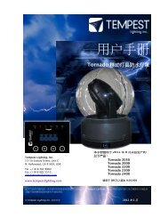
Dimensions, Weights and Projector Fit<br />
<strong>Cyclone</strong> Outdoor Dimensions<br />
Note: <strong>Cyclone</strong> HUSH dimensions are the same, except that there are no exhaust cowls on HUSH models.<br />
Air inlet Filters/Louvers<br />
Exhaust Cowls (Outdoor<br />
models only)<br />
DEC User Interface<br />
C<br />
Tempered optical glass<br />
projection window<br />
D<br />
Signal and Power conduit<br />
entries (Outdoor models)<br />
E<br />
Note: You must allow at<br />
least 4”/100mm<br />
clearance top and each<br />
side for airflow and<br />
latches<br />
A<br />
B<br />
DIM A DIM B* DIM C DIM D DIM E Weight Typical Projector Type<br />
8000 44”/112cm 48”/122cm 22”/56cm 28”/71cm 16”/40.6cm 175lb/80kg BARCO HDX<br />
8100 44”/112cm 48”/122cm 17”/43cm 34”/86cm 16”/40.6cm 160lb/73kg Panasonic PT-DS21K, DP Titan Quad<br />
8102 44”/112cm 48”/122cm 31”/79cm 34”/86cm 16”/40.6cm 220lb/100kg TWO x Panasonic PT-DS21K<br />
8120 44”/112cm 48”/122cm 20”/51cm 34”/86cm 16”/40.6cm 185lb/84kg Panasonic PT-EX16K<br />
8200 54”/137cm 58”/147cm 26”/66cm 34”/86cm 16”/40.6cm 220lb/100kg Christie Roadster<br />
8210 54”/137cm 58”/147cm 30”/76cm 36”/91cm 16”/40.6cm 230lb/105kg BARCO FLM, HDF<br />
8400 70”/178cm 74”/188cm 33”/84cm 34”/86cm 16”/40.6cm 320lb/145kg Christie Roadie HD35K<br />
8450 70”/178cm 74”/188cm 33”/84cm 34”/86cm 16”/40.6cm 320lb/145kg Christie D4K35, CP2210/20<br />
840B 31”/79cm 34”/86cm 26”/66cm 24”/61cm 8”/20.3cm 65lb/30kg Christie 35K Ballast Enclosure<br />
8500 61”/155cm 65”/165cm 36”/91cm 38”/97cm 16”/40.6cm 330lb/150kg BARCO HDQ 40K<br />
8600 70”/178cm 74”/188cm 39”/99cm 34”/86cm 16”/40.6cm 350lb/159kg Sony SRX-R320<br />
* Does not apply to HUSH models<br />
<strong>Cyclone</strong> Enclosure User <strong>Manual</strong> page 6
Open Slide and Door Dimensions<br />
B<br />
A<br />
B<br />
A<br />
B<br />
8000, 8100 Series, 8102 36”/92cm Same as height, Dim C, previous page<br />
8200 Series 38”/97cm Same as height, Dim C, previous page<br />
8400 Series 56”/142cm Same as height, Dim C, previous page<br />
<strong>Cyclone</strong> Enclosure User <strong>Manual</strong> page 7
2 Installation<br />
Safety and Warnings<br />
These warnings are for your protection. Failure to comply may result in serious injury or death.<br />
<strong>Tempest</strong> <strong>Lighting</strong>, <strong>Inc</strong>. assumes no responsibility for damages or injury incurred by misuse or<br />
mishandling of product.<br />
Do not attempt to install or operate the enclosure before fully reading and understanding this<br />
manual<br />
<br />
Never allow anyone who has not read this manual to open the enclosure or perform<br />
maintenance on the projector within.<br />
Never leave the enclosure unattended when open.<br />
<br />
Always make sure all bolts and latches are tight and safety locks are in place after performing<br />
any form of maintenance on the unit.<br />
Do not open any electrical boxes until power has been shut off to all supply lines to the<br />
enclosure (including the one powering the projector).<br />
Do not open the enclosure in wet weather.<br />
<strong>Cyclone</strong> Enclosure User <strong>Manual</strong> page 8
Planning<br />
<br />
Snow clearance:<br />
MINIMUM<br />
24”/60cm<br />
<br />
Observe the following MINIMUM clearances around enclosure for access and ventilation.<br />
4”/10cm *<br />
Same as height, + 2”/5cm<br />
Same as height, + 2”/5cm<br />
4”/10cm *<br />
4”/10cm<br />
* Note: Side clearance must be doubled when two enclosures are mounted side by side<br />
<strong>Cyclone</strong> Enclosure User <strong>Manual</strong> page 9
Mounting<br />
The <strong>Cyclone</strong> enclosure is provided with a pair of stainless steel Unistrut channels on the enclosure<br />
base, for mounting to your structure. You may use standard Unistrut accessories, or purchase<br />
mounting kits from <strong>Tempest</strong> <strong>Lighting</strong> – four kits are required per enclosure.<br />
<br />
<br />
<br />
<br />
<br />
Each Enclosure must be mounted with FOUR points.<br />
8400 and up must be mounted with SIX points when suspended from a structure.<br />
All mountings must be made using the two Unistrut channels on the base of the enclosure.<br />
<strong>Tempest</strong> <strong>Lighting</strong> recommends the use of stainless steel mounting hardware.<br />
IMPORTANT SAFETY NOTICE:<br />
Installer must ensure that all mounting points are secure and conform to local safety<br />
regulations. <strong>Tempest</strong> <strong>Lighting</strong> <strong>Inc</strong>. accepts no responsibility for damage or injury arising<br />
from inappropriate or unsafe installation.<br />
These mounting accessories are available from <strong>Tempest</strong>:<br />
4900.MB Stainless Steel Unistrut channel nut, bolt and<br />
washer. Four required per enclosure (6 when<br />
suspending <strong>Cyclone</strong> 8400 and up)<br />
4900.MC Stainless Steel Unistrut channel nut, bolt and<br />
pipe clamp, for pipes 1.5” (38mm) to 2” (50mm) OD.<br />
Four required per enclosure (6 when suspending<br />
<strong>Cyclone</strong> 8400 and up)<br />
.<br />
4925.MC Stainless Steel Unistrut channel nut, bolt and<br />
pipe clamp, for pipes 2” (50mm) to 2.5” (64mm) OD.<br />
Four required per enclosure (6 when suspending<br />
<strong>Cyclone</strong> 8400 and up)<br />
.<br />
<strong>Cyclone</strong> Enclosure User <strong>Manual</strong> page 10
Stacking <strong>Cyclone</strong> Enclosures<br />
<strong>Cyclone</strong> enclosures may be stacked, using the <strong>Cyclone</strong> Stacking Kit accessory.<br />
Item # 8000.SK<br />
4”/10cm<br />
<strong>Cyclone</strong> Enclosure User <strong>Manual</strong> page 11
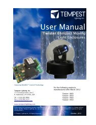
Cyclovator Tilt Kit<br />
<strong>Cyclone</strong> enclosures are often used on video mapping projects where the angle of the projected<br />
beam needs to be more than the projector’s lens shift range. The Cyclovator Tilt Kit allows the<br />
projector to be tilted up to 80˚up or down, and then returned to horizontal for servicing.<br />
IT IS A SAFETY REQUIREMENT that the projector only be slid out of the enclosure for<br />
service when the enclosure is horizontal. Many of the projectors used in <strong>Cyclone</strong><br />
enclosures are very heavy, and it is DANGEROUS to slide them when the enclosure is<br />
set at an angle.<br />
<br />
Installing the Cyclovator<br />
1. Cyclovator must be bolted securely to a solid structure or a concrete pad, using ½” or M12<br />
stainless steel hardware. Four fixing holes are provided in the Cyclovator base.<br />
2. The <strong>Cyclone</strong> enclosure bolts to the Cyclovator using six 5/16” stainless steel bolts<br />
provided. The bolts drop through the enclosure base and screw into threaded inserts in<br />
the Cyclovator arm.<br />
3. Using the hand crank, adjust the Cyclovator to the desired angle for the projection show.<br />
4. Loosen the set screw and slide the locking collar on the threaded rod to make contact<br />
with the Acme nut in the Cyclovator arm, and tighten the set screw. This is the show<br />
position stop.<br />
5. Now you can lower the enclosure to horizontal for service and return it accurately to the<br />
show position.<br />
Cyclovator Arm<br />
Acme Nut<br />
Locking Collar<br />
Hand Crank<br />
Fixing Point (x 4)<br />
<strong>Cyclone</strong> Enclosure User <strong>Manual</strong> page 12
<strong>Cyclone</strong> HUSH Enclosures<br />
<strong>Cyclone</strong> HUSH enclosures must be provided with an exhaust duct for exhaust air, from the top of<br />
the enclosure to a location where the noise of the <strong>Cyclone</strong> fans will not be heard. This is usually<br />
an insulated ceiling void, drop ceiling, an adjoining room, or an outside wall.<br />
The exhaust duct is normally installed by an air conditioning installer, and rated for airflow as<br />
follows:<br />
<strong>Cyclone</strong> 8000, 8100 HUSH 500cfm 0.25m 3 /s<br />
<strong>Cyclone</strong> 8200 and up 1,000cfm 0.50m 3 /s<br />
The <strong>Cyclone</strong> HUSH enclosure is supplied with a fan plate to be mounted at the far end of the duct.<br />
Installer must provide a 3-conductor flexible cable rated at 250VAC, 10 Amps, conforming to local<br />
electrical standards, to connect the fan plate to the <strong>Cyclone</strong> DEC controller, and pulled either<br />
through the duct or in a separate electrical conduit.<br />
Power and Signal<br />
Conduit Entries<br />
<strong>Cyclone</strong> Enclosure User <strong>Manual</strong> page 13
<strong>Cyclone</strong> HUSH Enclosure Top Surface Dimensions<br />
Smaller HUSH Enclosures (8000, 8100 Series)<br />
FRONT<br />
Exhaust<br />
Vent<br />
BACK<br />
Larger HUSH Enclosures (8102, 8200 and up)<br />
FRONT<br />
Exhaust<br />
Vent<br />
BACK<br />
<strong>Cyclone</strong> Enclosure User <strong>Manual</strong> page 14
<strong>Cyclone</strong> HUSH Remote Fan Plate<br />
Remote 2-Fan Plate<br />
<strong>Cyclone</strong> 8000, 8100 Series<br />
Remote 4-Fan Plate<br />
<strong>Cyclone</strong> 8102<br />
<strong>Cyclone</strong> 8200 and up<br />
1. Install the Remote fan plate at the end of the exhaust duct, with the airflow direction<br />
AWAY from the <strong>Cyclone</strong> enclosure. See illustration on p12<br />
2. Connect a 3-conductor wire rated at 10 Amps, 250 Volts to the terminals on the Remote<br />
Fan Plate.<br />
3. Pull the Fan wire through the duct to the Digital Enclosure Control (DEC) controller in the<br />
<strong>Cyclone</strong> enclosure.<br />
4. Terminate the fan wire to the DEC FAN 1 and Earth (Ground) Terminals as shown here:<br />
Fan Wire (European color<br />
codes shown here)<br />
<strong>Cyclone</strong> Enclosure User <strong>Manual</strong> page 15
3 Wiring<br />
All electrical work must be carried out by a properly licensed electrician, in compliance<br />
with local electrical standards. Failure to observe this point will void the factory warranty<br />
for the <strong>Tempest</strong> Enclosure.<br />
1 Switch off power to the branch circuit, carefully following lockout and tag-out procedures.<br />
Failure to do so could cause serious injury or death.<br />
2 You will need two electrical junction boxes, located within a short distance from the enclosure,<br />
one for power, one for signal (usually CAT5). Use outdoor-rated flexible conduit between the<br />
box and the enclosure, to allow for the back door to open.<br />
3 AC and signal circuits must be wired in separate conduits.<br />
AC<br />
Power<br />
208VAC<br />
or<br />
230VAC<br />
Picture<br />
Source<br />
Signal<br />
Conduit Entry Holes<br />
1 .875”/22.2mm for AC<br />
power<br />
2 .875”/22.2mm for Data<br />
(CAT5 or fiber)<br />
3 2”/50.8mm for pre-wired<br />
signal cables with large<br />
connectors.<br />
Flexible Conduit<br />
Conduit Entries may be fitted<br />
with flexible conduit fittings<br />
or cable glands (not included)<br />
Conduit Entry Holes – 8400 Model (for Christie Roadie)<br />
The smaller conduit entry holes (A) accept US ½”<br />
conduit fittings, and international 20-22mm (OD)<br />
conduit fittings.<br />
The larger entry holes (B) accept 2”/50mm OD fittings<br />
for signal cables with larger molded connectors.<br />
The CamLok Connectors (C) are for the DC ballast<br />
cables.<br />
A A B B C C<br />
<strong>Cyclone</strong> Enclosure User <strong>Manual</strong> page 16
One or Two Power Circuits?<br />
1<br />
1 2<br />
Single Feed<br />
Split Feed<br />
<strong>Tempest</strong> enclosures may be wired on single or double line supplies. On a single feed, both enclosure<br />
and projector are permanently on. With a split feed supply, you can switch off the projector when not<br />
in use, while the enclosure continues to protect it 24/7.<br />
Single Feed<br />
Enclosure and projector are<br />
permanently on.<br />
Enclosure and Projector must be<br />
rated for the same voltage.<br />
Supply must be rated for projector<br />
current plus 150 watts.<br />
Supply must be permanently ON.<br />
Split feed<br />
Enclosure power must be permanently ON.<br />
Projector power may be switched off.<br />
Enclosure power must be rated for 1150W<br />
Projector power must be rated for the<br />
projector (see projector manual).<br />
Projector and enclosure power must be<br />
same voltage.<br />
<strong>Cyclone</strong> Enclosure User <strong>Manual</strong> page 17
Single Feed Operation (factory default)<br />
Enclosure and projector share the same electrical circuit.<br />
Circuit must be powered ON 24/7.<br />
Connect incoming power to the terminals labeled MAINS:<br />
(E) Earth/Ground<br />
(L) Live<br />
(N) Neutral<br />
1<br />
E L N<br />
Split Feed Operation<br />
Enclosure and projector have separate electrical feeds.<br />
The enclosure circuit must be powered ON 24/7.<br />
When splitting the feeders, both circuits should be on the same phase and at the same supply<br />
voltage.<br />
1 Use a wire cutter to cut the copper links on the<br />
DEC3.2 board in four places.<br />
2 Connect incoming ENCLOSURE power to the<br />
terminals labeled MAINS. This supply MUST be<br />
maintained 24/7.<br />
(E) Earth/Ground (L) Live (N) Neutral<br />
E L N<br />
Projector<br />
Power<br />
E L N<br />
Enclosure<br />
Power<br />
3 Connect incoming PROJECTOR power to the<br />
terminals labeled SPLIT:<br />
(E) Earth/Ground (L) Live (N) Neutral<br />
<strong>Cyclone</strong> Enclosure User <strong>Manual</strong> page 18
Power Connections<br />
IMPORTANT<br />
<strong>Tempest</strong> enclosures are supplied for either 120VAC 50/60Hz, or 208-240VAC,<br />
50/60Hz operation. <strong>Tempest</strong> <strong>Lighting</strong> is not liable for damage or failure to<br />
operate correctly due to connection to an inappropriate electrical supply.<br />
ALL ELECTRICAL CONNECTIONS MUST BE UNDERTAKEN BY A QUALIFIED<br />
ELECTRICIAN, IN COMPLIANCE WITH LOCAL NORMS AND STANDARDS.<br />
Cut here for split<br />
supply operation<br />
Projector<br />
receptacle<br />
Fan 2<br />
Heater(s)<br />
Fan 1<br />
Projector Supply<br />
(split mode)<br />
Enclosure Supply<br />
(100-250VAC 50/60Hz)<br />
Note: wire colors may differ depending on applicable electrical standards. European wire colors are shown here.<br />
IMPORTANT: MAKE SURE THAT TERMINAL SCREWS ARE FULLY BACKED OUT BEFORE INSERTING WIRES.<br />
<strong>Cyclone</strong> Enclosure User <strong>Manual</strong> page 19
Auxiliary Power Outlet<br />
An auxiliary IEC power outlet is provided for any auxiliary equipment needed (routers, CD players<br />
etc) in the enclosure. Wiring is different dependent on electrical standard:<br />
North America (208 volt <strong>Cyclone</strong> enclosures with .US part # suffix)<br />
AUX receptacle is UNWIRED. Installer should run a separate 120V supply to back of IEC<br />
C14 receptacle. Receptacle is rated 250V, 10 Amps in Europe, 15 Amps North America.<br />
International (230 volt <strong>Cyclone</strong> enclosures with .IN part # suffix)<br />
AUX receptacle is wired in parallel with the projector outlet (NEMA 30 Amp or IEC C19).<br />
AUX POWER<br />
IEC C14 (rewireable plug supplied)<br />
PROJECTOR (connector type<br />
varies dependent on projector<br />
type and power)<br />
Note: Projector Connector<br />
<strong>Cyclone</strong> 8000 and 8100 Series enclosures are provided with IEC C19 projector power outlets.<br />
<strong>Cyclone</strong> 8200 enclosures and up are equipped with NEMA (US-style) 30 Amp 250 Volt Twistlock<br />
receptacles (NEMA L6-30). For shipments outside North America a mating plug is supplied for<br />
wiring to the projector power cable.<br />
<strong>Cyclone</strong> Enclosure User <strong>Manual</strong> page 20
<strong>Cyclone</strong> 840B Ballast Enclosure<br />
Christie Roadie and some Christie Cinema Projectors require a separate Ballast, which is too large<br />
to fit inside the projector enclosure.<br />
Christie allows 100’/30m of DC cable between the ballast and the projector. For outdoor<br />
installations when it is not possible to house the ballast in a convenient equipment room, a<br />
<strong>Cyclone</strong> 840B ballast enclosure must be used.<br />
As well as the ballast cables there are two DB15 signal cables and one IEC C14 auxiliary power<br />
cable that must be connected between the ballast and the projector.<br />
NOTE: The 840B Ballast enclosure comes with 10’/3m DC pigtails to connect to the <strong>Cyclone</strong><br />
projector enclosure. If you are using the 840B you do NOT need to purchase DC cables from<br />
Christie.<br />
Signal and Aux Power conduit entry<br />
(2”/50.8mm)<br />
AC Power conduit entry<br />
(1”/25.4mm)<br />
10’/3m DC Pigtails. Note: Camlok<br />
connectors for Roadie projector,<br />
Ring Lugs for Cinema projectors<br />
<strong>Cyclone</strong> Enclosure User <strong>Manual</strong> page 21
Power Connections to 840B Enclosure<br />
The 840B enclosure requires a three phase 208V supply in North America, and a 3-phase + neutral<br />
380-415V supply in 230V countries.<br />
1. Remove the enclosure cover and the DEC Cover<br />
inside the enclosure. Loosen the two knurled nuts<br />
and slide the cover up.<br />
Ballast Power<br />
Receptacle<br />
Knurled knobs<br />
DEC Cover<br />
2. Connect the incoming power cable to the terminal<br />
block mounted on the DEC chassis.<br />
PHASE 1<br />
PHASE 2<br />
PHASE 3<br />
GROUND<br />
Note: US System shown here.<br />
International Systems will also<br />
have a Neutral connection.<br />
3. Replace the DEC Cover<br />
<strong>Cyclone</strong> Enclosure User <strong>Manual</strong> page 22
4. Place the Christie Ballast in position and secure in place with the tie-down strap provided<br />
Tie-down Strap<br />
Ballast<br />
Interlock<br />
Connectors<br />
5. Plug the ballast power cable into the 3-phase Ballast Power receptacle provided<br />
6. Plug the two Camlok tails into the ballast. BE SURE TO TWIST CLOCKWISE to make a good<br />
connection.<br />
7. Connect the two Interlock cables to the Ballast D-Connectors and connect Aux power to<br />
the projector to the Ballast Aux power outlet.<br />
8. Replace the Enclosure cover.<br />
<strong>Cyclone</strong> Enclosure User <strong>Manual</strong> page 23
4 Digital Enclosure Control – DEC3.3 TM<br />
with Goldilocks TM<br />
Heater Fan On Relay<br />
Temp<br />
DMX<br />
Lamp<br />
ESC<br />
OK<br />
DEC3.3 TM – that’s Digital Enclosure Control, third Generation, revision 3 – is the brain of your<br />
<strong>Tempest</strong> enclosure. It will maintain the internal environment in a comfortable temperature and<br />
humidity range, and prevent condensation – the real killer of outdoor equipment. DEC3.3<br />
monitors internal temperature, humidity and lamp current at all times, and uses this information<br />
to control the enclosure’s lamp relay, fan(s) and heater(s). It can report back over the DMX cable,<br />
using the RDM protocol (Remote Device Management) if desired.<br />
From summer 2013 DEC is running <strong>Tempest</strong>’s new Goldilocks TM operating system (patents<br />
pending). A completely new OS, Goldilocks analyzes temperature and humidity trends, targeting<br />
and maintaining safe ranges, and acting to prevent condensation before it happens. Goldilocks is<br />
also much more energy-efficient than previous generations, so your equipment is always in the<br />
Goldilocks zone, and you save money too.<br />
<strong>Cyclone</strong> Enclosure User <strong>Manual</strong> page 24
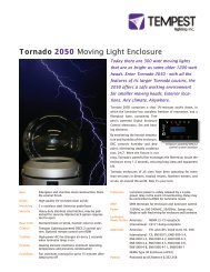
DEC3.3 Schematic<br />
AC Supply (must be on<br />
at all times)<br />
Split Feed (optional)<br />
Cut the links for split<br />
feed operation<br />
<br />
Sensor<br />
X<br />
X<br />
AC Heater(s)<br />
AC Fan(s)<br />
OUT<br />
IN<br />
OUT<br />
IN<br />
DMX/RDM – RS485<br />
(Optional)<br />
Which Controller?<br />
The following Table shows which controller is used in different types of <strong>Tempest</strong> Enclosure. This<br />
section does NOT apply to enclosures with <strong>Tempest</strong> MiniDEC TM Control<br />
Enclosure Type DEC3.3/Goldilocks MiniDEC<br />
Blizzard Indoor •<br />
HUSH<br />
•<br />
Outdoor<br />
•<br />
<strong>Cyclone</strong> HUSH •<br />
Outdoor<br />
•<br />
Thunder Outdoor Special order •<br />
Tornado Outdoor •<br />
Twister Outdoor •<br />
<strong>Cyclone</strong> Enclosure User <strong>Manual</strong> page 25
DEC3.3 Main Functions<br />
1 Sense current to projector (lamp on/off)<br />
2 Record lamp hours<br />
3 Monitor temperature and humidity inside Enclosure<br />
4 Maintain temperature at safe operating level<br />
5 Maintain relative humidity within safe limits<br />
6 Prevent condensation<br />
7 Isolate projector in case of unsafe temperature<br />
8 Report status over RDM<br />
9 (Optional) remote projector relay control over DMX<br />
DEC3.3 constantly monitors the following parameters:<br />
• Projector/Luminaire power<br />
• Line Voltage<br />
• Temperature<br />
• Humidity<br />
DEC 3.3’s patented Goldilocks TM algorithm uses a combination of heaters and fans to maintain a<br />
safe operating temperature and a safe relative humidity level that will not allow condensation to<br />
take place.<br />
As air is heated it is able to support more moisture without condensing, so Goldilocks uses heat<br />
to raise the air temperature inside the enclosure in the event that relative humidity approaches<br />
dewpoint.<br />
Factory Settings – Basic Mode<br />
In most applications, DEC3.3 will operate correctly with its factory default settings, in Basic<br />
operating mode.<br />
You do not need to do anything. Please skip to the Power Connections section below.<br />
If your needs are more complex, read on.<br />
<strong>Cyclone</strong> Enclosure User <strong>Manual</strong> page 26
Operating Modes<br />
DEC3.3 may operate in one of four modes, set using either the Front Panel or by RDM control. In<br />
all configurations, the projector inside the enclosure may also be an RDM enabled device.<br />
Basic Mode (factory setting)<br />
• Standard temperature settings<br />
• DMX and RDM disabled<br />
• Best for standalone operation<br />
Monitor Mode<br />
• As Basic mode, plus:<br />
• RDM status reporting<br />
• RDM configuration – settings may be changed remotely or at the enclosure control<br />
panel<br />
• DEC3.3 does not require a DMX signal to operate<br />
Control Mode<br />
• As Basic mode, plus:<br />
• Enclosure functions as a 1-channel DMX device, with remote control of the lamp relay<br />
o DMX level > 75% enables normal relay operation (normally ON)<br />
o DMX level < 25% disables normal relay operation (relay turns OFF)<br />
o This allows you to force a hard reset of the lamp relay in the event of a<br />
projector malfunction<br />
• Control mode is recommended for show control applications, but can be risky in live<br />
show operation, since the DMX slot used for the enclosure MUST be kept high to<br />
prevent the lamp relay from opening.<br />
Service Mode<br />
• For trained service personnel only<br />
• Normal operation is suspended and the enclosure functions as a 3-channel DMX<br />
device:<br />
o Lamp Relay (Slot 1)<br />
o Fans (Slot 2)<br />
o Heater (Slot 3)<br />
• Service mode is ONLY for troubleshooting – DO NOT use Service mode for normal<br />
operation.<br />
<strong>Cyclone</strong> Enclosure User <strong>Manual</strong> page 27
DEC3.3 Control Parameters<br />
Temperature and Humidity Ranges:<br />
Low<br />
Cooling Fan(s)<br />
Trip Temp<br />
(55-70˚C, Default 60 ˚C)<br />
Upper Temp<br />
(35-50˚C, Default 40 ˚C)<br />
Relative Humidity<br />
(50-90%,<br />
Default 80%)<br />
Trend Temp<br />
(Dynamic)<br />
IdealTemp (Dynamic, based<br />
on Relative Humidity)<br />
High<br />
LowerTemp<br />
(0-10˚C, Default 0 ˚C)<br />
Heater(s)<br />
Notes:<br />
1 In moving light enclosures the temperature sensor is located in the exhaust<br />
airflow. Temperatures shown may be higher than those around the projector.<br />
2 We recommend using the factory default settings for several weeks or months<br />
before making any changes. In most cases they will not be necessary.<br />
Max Humidity Range 50-90%, Default 80%<br />
The threshold at which air inside the enclosure is heated to raise dewpoint and<br />
prevent condensation. Setting a higher Max Humidity is not a bad thing in highhumidity<br />
climates. Setting the Max Humidity too low will result in unnecessary<br />
heating and excessive energy use. So set the Max Humidity at the top end of the<br />
relative humidity likely to be experienced on site.<br />
DMX Address Range 001-510, Default 001<br />
Sets the DMX address for the lamp relay control. (See also DMX Response)<br />
Set Temp Units Display Degrees Celsius or Fahrenheit. Default Celsius<br />
Note that temperature settings must always be Celsius.<br />
Lamp Hours Default 0000<br />
Counts lamp hours – you must reset to zero when changing lamps.<br />
Lamp On Point The lamp current at which DEC detects the projector/luminaire lamp is running.<br />
Default is 1 Amp, which allows for equipment fans and power supplies to run<br />
without changing the air in the enclosure. Lamp on point may be set in 0.2 Amp<br />
increments between 0.2 Amps and 2.0 Amps.<br />
<strong>Cyclone</strong> Enclosure User <strong>Manual</strong> page 28
DMX Connections<br />
DMX refers to USITT DMX512, a commonly used control protocol in the entertainment industry,<br />
running over RS485. Consult USITT DMX installation guidelines when laying out a system, or<br />
employ a qualified DMX system integrator.<br />
A DMX network will be required if:<br />
a) The projector inside the enclosure requires a DMX control signal<br />
b) You wish to monitor the enclosure using RDM<br />
c) You wish to control the enclosure lamp relay over DMX<br />
DMX Terminations<br />
Note: DMX will not normally be used in projector installations.<br />
Pinout: (1) Ground, (2) Data -, (3) Data +.<br />
DMX Connectors:<br />
❹ ❸ ❷ ❶<br />
1 DMX IN from network<br />
2 DMX OUT to projector (or to network<br />
if not controlling projector)<br />
DMX OUT to<br />
next DMX device<br />
DMX IN from<br />
outside world<br />
3 DMX IN from projector<br />
4 DMX OUT to network<br />
Note: If the enclosed equipment does not<br />
use DMX, then connector (2) on the<br />
controller is DMX OUT for the enclosure.<br />
DMX terminal Pinout Detail<br />
DMX Line Terminations<br />
DMX cable runs must be terminated at<br />
the far end of the cable run with a<br />
termination resistor as detailed in the<br />
DMX512 standard.<br />
The individual equipment installed inside the<br />
<strong>Tempest</strong> enclosures must NOT be terminated.<br />
+ ‒ G<br />
DMX OUT<br />
+ ‒ G<br />
DMX IN<br />
LIGHT<br />
+ ‒ G<br />
DMX OUT<br />
LIGHT<br />
+ ‒ G<br />
DMX IN<br />
It is recommended that any line termination is<br />
done using the 3-pin terminal connector fitted<br />
to the DEC3.3 control circuit board.<br />
<strong>Cyclone</strong> Enclosure User <strong>Manual</strong> page 29
Remote Device Management (RDM)<br />
RDM refers to ANSI E1.20, a control protocol in the entertainment industry used for device<br />
configuration and monitoring, and essentially an “extension” of DMX512. The use of RDM is<br />
optional, and uses the same RS485 cable connection as DMX512, so no additional wiring is<br />
required if DMX is already present. The user must ensure that any DMX splitters or other routing<br />
devices used are RDM operable as well as DMX use. <strong>Tempest</strong> strongly recommends working with a<br />
qualified RDM system integrator when designing an RDM network. Go to www.tempest.org for<br />
contact information.<br />
RDM and RDM Integration<br />
DEC3.3’s RDM implementation allows system integrators to remotely configure, control or monitor<br />
DEC3.3 attributes, including:<br />
• Relative Humidity<br />
• Air Temperature<br />
• PCB Temperature<br />
• Lamp Current<br />
• Elapsed Lamp Hours<br />
• Lamp Relay Status<br />
• Fan Relay Status<br />
• Heater Relay Status<br />
• DMX Status<br />
• DMX Start Address<br />
• DMX Personality (RDM Mode)<br />
• Device Type<br />
• Device Label<br />
• Software Version<br />
RDM is an effective and powerful tool for commissioning and monitoring an<br />
installation, particularly in large systems. For further guidance, please<br />
consult a qualified RDM system integrator. <strong>Tempest</strong> <strong>Lighting</strong> warrants<br />
DEC3.3 to be compliant with the RDM standard, but is not an RDM systems integrator, and can<br />
offer only basic guidance on RDM utilization.<br />
<strong>Cyclone</strong> Enclosure User <strong>Manual</strong> page 30
Control Interface<br />
LED Indicators<br />
Heater ON (Green) Heater is ON, to maintain lower temperature<br />
level or to prevent condensation<br />
Fan ON (Green) Lamp is ON, or Temperature is HIGH and<br />
Fan is cooling enclosure. Short burst when lamp<br />
off indicates fan moving air to stabilize<br />
temp/humidity<br />
Lamp On ON (Green) Current sensing shows lamp is ON<br />
Lamp hour counter is running<br />
OFF<br />
Current sensing shows lamp is OFF<br />
Lamp hour counter is not running<br />
Lamp Relay ON (Green) Lamp relay is closed (normal)<br />
Projector power receptacle is energized<br />
ON (Red) Lamp relay is open due to over-temperature<br />
event. Projector power receptacle is isolated.<br />
Temp<br />
FLASHING<br />
(Green)<br />
Temperature is below lower temp setting<br />
ON (Green)<br />
Temperature is in normal range<br />
ON (Amber)<br />
ON (Red)<br />
Humidity is above target limit<br />
Temperature is above top setting<br />
FLASHING (Red) Temperature is above Trip level<br />
Projector power is isolated<br />
DMX OFF DEC3.3 is in BASIC Mode – DMX not used. OR<br />
DEC3.3 is in Monitor or Control Mode and no<br />
valid DMX or RDM packet has been detected.<br />
ON (GREEN) Good DMX or RDM data packet received.<br />
ON (RED)<br />
Control Mode: DMX Fail. A previously good DMX<br />
signal has failed.<br />
Monitor Mode: No RDM information being<br />
received (this is normal)<br />
<strong>Cyclone</strong> Enclosure User <strong>Manual</strong> page 31
Control Display<br />
The display on the Control display provides additional status information, depending on the<br />
operating mode:<br />
Basic Mode & 28˚C 47% internal temperature, relative humidity<br />
Monitor Mode 209V OFF line voltage, lamp status<br />
DMX Mode & 28˚C 47% internal temperature, relative humidity<br />
Service Mode 209V OFF line voltage, lamp status<br />
Alternating with:<br />
DMX: 001 DMX Start Address<br />
No DMX DMX Status<br />
Control Interface Operation<br />
The Control Interface is normally LOCKED.<br />
To UNLOCK, hold ESC and OK together for 5 seconds.<br />
You are now in the CONTROL MENU<br />
Use to scroll up and down the menu.<br />
Press OK to enter a menu item<br />
Use to set the item parameter, or to scroll to the next menu level.<br />
Use ESC to go BACK, and OK to confirm settings ( ).<br />
To LOCK, hold ESC for 5 seconds.<br />
Menu will time out after ten minutes.<br />
<strong>Cyclone</strong> Enclosure User <strong>Manual</strong> page 32
Control Menu<br />
SET DMX OPTIONS<br />
SET DMX MODE<br />
From the Front Panel, this menu item allows the user to check (and if necessary<br />
change) the RDM mode.<br />
BASIC<br />
Standalone operation, no DMX/RDM (factory default)<br />
MONITOR Standalone, plus support for RDM remote configuration and<br />
monitoring<br />
CONTROL Monitor, plus use of a single DMX slot to control Lamp relay<br />
SERVICE Monitor, plus use of three DMX slots to control Lamp, Heater and<br />
Fan<br />
Important: Please ensure that the DEC3.3 is NOT left in Service Mode.<br />
SET DMX ADDRESS (in Monitor, Control or Service modes)<br />
Select a DMX starting address in the range 001 to 510<br />
1 – Lamp Relay<br />
In Service Mode an addition two slots are available<br />
2 – Fan Duty Control<br />
3 – Heater Duty Control<br />
Note that the DMX control is designed using a SAFETY pile-on Logic. So the DMX<br />
input can only override automatic settings within safe limits.<br />
SET DMX CURVE<br />
DMX Curves affect the way the fixture relay is controlled in Control Mode.<br />
DMX levels are shown as %.<br />
Response Curve 1 (default)<br />
DMX level 0-25 Relay disabled (open)<br />
DMX level 26-75 No change to relay status<br />
DMX level 76-100 Relay enabled (normally closed)<br />
Response Curve 2<br />
DMX level 0-19 No change to relay status<br />
DMX level 20-40 Relay disabled (open)<br />
DMX level 41-59 No change to relay status<br />
DMX level 60-80 Relay enabled (normally closed)<br />
DMX level 81-100 No change to relay status<br />
SET DMX RESPONSE<br />
DMX Response sets a delay time before DMX Control Mode settings are acted on.<br />
Setting a response delay of a few seconds would prevent unintended fixture relay<br />
state changes in the event of a short accidental change in DMX level.<br />
<strong>Cyclone</strong> Enclosure User <strong>Manual</strong> page 33
NOTE: from firmware revision 0.00.100, DEC holds last valid DMX level if DMX is<br />
interrupted.<br />
Response Delay Values are:<br />
No Delay (default), 1, 2, 5, 10, 15, 20, 30, 60 seconds.<br />
SET TEMP UNITS<br />
Choose to display temperature values in Celsius or Fahrenheit (default Celsius)<br />
Note that temperature settings must be entered in Celsius.<br />
SET TEMP RANGES<br />
Set three temperature trigger points for Bottom, Top and Trip temperatures, in °C.<br />
SET TEMP LOWER (minimum temperature to be maintained)<br />
(default 0°C, permissible range 0-10°C).<br />
SET TEMP UPPER (maximum desired temperature)<br />
(default 40°C, permissible range 35-50°C).<br />
SET TEMP TRIP (temperature at which load will be isolated – see note)<br />
(default 60°C, permissible range 55-70°C).<br />
Note: A thermal emergency is when enclosure ventilation fails with the lamp on, in which case the<br />
temperature will rise very quickly. To avoid nuisance tripping we recommend setting a higher Trip<br />
temperature, 60°C or above.<br />
SET MAX HUMIDITY<br />
(default 80%, permissible range 50-90%).<br />
Set target maximum relative humidity level. This should be set at or a few % higher than<br />
the normal high humidity levels expected on site.<br />
SET LAMP ON POINT<br />
The lamp current at which DEC detects the projector/luminaire lamp is running. Default is<br />
1 Amp, which allows for equipment fans and power supplies to run without changing the<br />
air in the enclosure. Lamp on point may be set in 0.2 Amp increments between 0.2 Amps<br />
and 2.0 Amps.<br />
RESET LAMP HOURS<br />
Reset each time you change the lamp in the projector/projector.<br />
Make this a part of your maintenance instructions.<br />
STATUS DISPLAY<br />
View current status information, using the arrow keys to scroll through:<br />
a) Humidity – relative humidity in %<br />
b) Air temperature, in degrees C or F<br />
c) PCB temperature (this will usually be significantly higher than air temperature)<br />
d) Voltage – line Voltage reaching the DEC<br />
<strong>Cyclone</strong> Enclosure User <strong>Manual</strong> page 34
e) Current being drawn by projector/light, in Amps<br />
f) Lamp Hours elapsed since last reset<br />
g) Firmware version<br />
RDM Monitoring and Configuration<br />
All the features accessible over the DEC3.3 control panel are also available over RDM. Just how<br />
this information is displayed will depend on the RDM interface used. These screen shots were<br />
taken running the GetSet program in Windows 7, and connecting to a DEC3.3 controller using a<br />
RDM TRI MK1 interface, <strong>Tempest</strong> part # 2000.190<br />
This view shows a single<br />
DEC3.2 test unit that has been<br />
correctly discovered and<br />
labeled by the GetSet software<br />
suite, and a log of RDM<br />
messages.<br />
This RDM interface provides a<br />
graphic view of the various<br />
sensor functions supported by<br />
DEC3.2 and up<br />
Important:<br />
Check that your RDM interface<br />
vendor has tested his interface<br />
with <strong>Tempest</strong> enclosures and<br />
all other RDM devices you plan<br />
to use on the same network.<br />
<strong>Cyclone</strong> Enclosure User <strong>Manual</strong> page 35
Firmware Upgrade over RDM<br />
DEC3.3 firmware<br />
is fieldupgradeable,<br />
using RDM. A field<br />
upgrade requires a<br />
JESE RDM TRI MK1<br />
interface to be<br />
connected to the<br />
DMX network on<br />
which the DEC3.3<br />
is located, and the<br />
use of JESE GetSet<br />
software. The kit<br />
is available from<br />
<strong>Tempest</strong> under<br />
part # 2000.190.<br />
<strong>Cyclone</strong> Enclosure User <strong>Manual</strong> page 36
5 Mounting the Projector<br />
IMPORTANT! READ THIS FIRST<br />
For safety, this must be done by two or more people.<br />
IMPORTANT: The projector enclosure MUST be securely mounted BEFORE you attempt to<br />
install the projector.<br />
The enclosure must be horizontal for projector mounting and projector service. If the<br />
projection angle is NOT horizontal, a Cyclovator Tilt Kit should be used, and the projector<br />
returned to horizontal for projector mounting and service.<br />
<br />
<br />
1. <strong>Cyclone</strong> enclosures may be provided with front or rear projector slides (the projector tray slides<br />
out of either the front or rear of the enclosure), to customer order.<br />
2. Depending on the projector type and orientation, your mounting method may differ.<br />
a. Generally, the projector stands on the projector tray, and is bolted through slots from<br />
below to lock in place.<br />
Projector Tray<br />
Slide Bolt (x 2)<br />
Projector Bolt, flat<br />
washer, spring washer.<br />
Type and quantity vary<br />
by projector.<br />
Projector Tray.<br />
Slides are rated<br />
@ 500lb/227kg.<br />
Projector Bolt<br />
Slots allow<br />
front/back<br />
adjustment<br />
<strong>Cyclone</strong> Enclosure User <strong>Manual</strong> page 37
. For projectors without threaded sockets on the underside, clamps are provided to secure<br />
the projector feet to the projector tray, to prevent movement.<br />
Projector Foot Clamp<br />
slides over feet and<br />
bolts to tray front<br />
and back.<br />
c. Portrait enclosures have a vertical mounting frame. The projector generally bolts to the<br />
frame.<br />
Projector Bolt, flat<br />
washer, spring washer.<br />
Type and quantity vary<br />
by projector<br />
Projector Tray<br />
Slide Bolt (x 2)<br />
3. Release the two projector tray slide bolts and fully extend the tray.<br />
4. Set the projector on the tray and check for center. The projector should be centered and<br />
mounted with the front of the lens above the end of the tray.<br />
a. Portrait Enclosures: Bolt the projector to the vertical projector mount, using the bolts<br />
provided. You can still adjust the feet, but this will require more people to:<br />
i. Support the weight of the projector<br />
ii. Loosen/tighten mounting bolts<br />
iii. Lower/raise projector feet<br />
Portrait Projector<br />
Mounting Frame<br />
mounts on<br />
projector tray<br />
<strong>Cyclone</strong> Enclosure User <strong>Manual</strong> page 38
5. Return the projector tray into the <strong>Cyclone</strong> enclosure and check that the lens is aligned with the<br />
projection window. Projectors with wide-angle lenses should be positioned with the front of the<br />
lens as close to the window as possible to avoid clipping.<br />
Lens should be<br />
close to center of<br />
projection window<br />
6. Connect all cables to the projector, threading them through the flexible cable management<br />
track. Allow for 7-13’/2-4m of cable inside the enclosure to run through the cable management<br />
track to the projector. Actual length depends on the <strong>Cyclone</strong> model, front or rear tray slide, and<br />
the location of connectors on the projector body.<br />
7. Plug the projector into the Projector power outlet on the back door.<br />
Auxiliary Power Outlet<br />
(IEC C14) *<br />
Projector Power Outlet<br />
(IEC C14 or NEMA L6-30 Twistlock)<br />
*IMPORTANT: North American models (model # with .US suffix, running on 208V or 240V<br />
feeds): The Auxiliary power receptacle is NOT connected. Run a 15 Amp 120V circuit into the<br />
enclosure and terminate on the back of the IEC C14 receptacle.<br />
International models (with .IN model # suffix, running on 230V feeds): the Auxiliary power<br />
socket is wired in parallel with the projector outlet.<br />
8. Slide the tray back into the <strong>Cyclone</strong> enclosure. Power up the projector and adjust the projector<br />
feet as needed.<br />
9. Pull the tray out of the enclosure and either:<br />
a. Bolt the projector through the mounting slots to the tray using the bolts and washers<br />
provided. DO NOT OVERTIGHTEN – THIS MAY DAMAGE THE PROJECTOR.<br />
<strong>Cyclone</strong> Enclosure User <strong>Manual</strong> page 39
. Slide the projector foot clamps in place over the projector feet and tighten the bolts<br />
through the projector tray slots to secure in place.<br />
10. Return the projector tray to the enclosure and lock the two slide bolts in place.<br />
Airflow Chimneys<br />
Certain projectors in certain enclosure types require additional airflow deflectors, baffles or chimneys<br />
to direct the projector’s exhaust air towards the exhaust fans/duct and prevent recirculation and<br />
overheating.<br />
These parts will be supplied as needed with your enclosure, and are generally mounted either on the<br />
enclosure frame or the projector tray. If they are not included, they should not be needed.<br />
Christie Roadster Projectors<br />
<strong>Cyclone</strong> 8200 enclosures for Christie Roadsters are supplied with a special airflow chimney that<br />
clamps to the lamp door at the back of the projector. The lamp door may still be opened for<br />
relamping without having to remove the airflow chimney. The Chimney will be packed inside the<br />
enclosure for shipping.<br />
Mounting clamp secures with<br />
two screws through top<br />
Christie Roadster/J-Series<br />
14-22K Lamp Door<br />
<strong>Cyclone</strong> 8200 Airflow<br />
Chimney clamps to<br />
projector lamp door<br />
<strong>Cyclone</strong> Enclosure User <strong>Manual</strong> page 40
Christie Roadie HD35K Projectors<br />
These projectors (mounted in <strong>Cyclone</strong> 8400 enclosures) use an external DC ballast to supply power to<br />
the projector lamp, over two 200 Amp single pole cables, with CamLok type single pole connectors.<br />
Christie specifies a cable run between ballast and projector of up to 100’/30m.<br />
1. <strong>Cyclone</strong> 8400 Enclosures supplied for use with these projectors include two CamLok panel<br />
receptacles on the rear door, and internal DC wiring to the back of the projector. The cable<br />
loop inside the enclosure is approximately 10’/3m, so the maximum permissible cable length<br />
from the ballast to the outside is therefore reduced to 90’/27m.<br />
2. When the projector is placed on the projector tray, connect the DC cables to the receptacles at<br />
the back of the projector BEFORE fixing the projector is in place.<br />
3. Make sure that both Camlok plugs are fully inserted, and twisted ¼ turn clockwise.<br />
4. Set the projector in position, and feed any cable slack back through the cable track, before<br />
fixing the projector in place.<br />
<strong>Cyclone</strong> Enclosure User <strong>Manual</strong> page 41
6 Closing up the Enclosure<br />
1 Check all electrical connections<br />
2 Clear the enclosure and projector of all dust<br />
and debris.<br />
3 Check that the power switch on the projector<br />
is in the ON position.<br />
4 Complete all signal connections, following<br />
projector manufacturer’s instructions.<br />
<br />
5 Test projector<br />
6 Tie down cables so that they will not touch<br />
heaters or fans.<br />
7 Replace the cover on the Blizzard base. This<br />
may require two people.<br />
<br />
Congratulations! Your system is now ready for use.<br />
<strong>Cyclone</strong> Enclosure User <strong>Manual</strong> page 42
7 Operation<br />
<br />
<br />
<br />
<br />
Outdoor Enclosures must receive power at all times. Enclosure, and will not provide proper<br />
protection for the projector inside if it is not connected to AC power.<br />
Unless the enclosure or projector is undergoing routine maintenance, the cover should be in<br />
place and locked down at all times.<br />
Only authorized personnel should open the enclosure (see maintenance warnings in the next<br />
section).<br />
If the ambient temperature is high enough, the over-temperature shutdown feature may engage<br />
and temporarily cut off power to the projector. Once the temperature reaches acceptable levels,<br />
power will be automatically restored after 5 minutes.<br />
<strong>Cyclone</strong> Enclosure User <strong>Manual</strong> page 43
8 Routine Maintenance<br />
It is very important to perform routine maintenance on both the enclosure and the projector<br />
within. Failure to do so may reduce lifetime for both the enclosure and the projector.<br />
Note<br />
Maintenance schedules depend on location and environment. The times given here are general<br />
guidelines for you to use. It is up to you to judge whether maintenance should be done more<br />
often. We do advise doing these tasks no less often than mentioned here.<br />
Safety<br />
<br />
<br />
<br />
<br />
<br />
Although maintenance can be performed while the enclosure is powered, it is safer to carry it out<br />
with the power disconnected with proper lockout and tag out procedures followed.<br />
Be aware that once the enclosure has had power applied to it, the heater will get hot and the fans<br />
will start to turn. Make sure that your hands are clear of these areas before applying power to<br />
the enclosure.<br />
Only authorized personnel should perform maintenance on the enclosure or projector<br />
Do not service the unit in the rain or other adverse weather conditions (snow, sleet, high winds,<br />
etc.).<br />
Be aware that the cover is a large object that can be awkward to handle, especially when standing<br />
on a ladder or scaffolding.<br />
Inspection Checklist: - Every Three (3) Months<br />
<br />
<br />
<br />
<br />
<br />
<br />
<br />
All weep (drain) holes should be clear<br />
All vents should be free of debris<br />
Enclosure should be free of debris both inside and out<br />
Bolts should be tight<br />
Lid seal should be in good condition, Check seal inside and out for gaps.<br />
Window should not be cracked<br />
Fans should be moving (it will be necessary to have the power on to check this), with<br />
corresponding indicator status<br />
Except for the last two items (concerning globe and fan), problems with any of these things can<br />
be easily remedied. Contact technical support for problems with the last two items.<br />
<strong>Cyclone</strong> Enclosure User <strong>Manual</strong> page 44
Air Filter Replacement<br />
The air filters should be removed and checked on a regular basis. We recommend initial inspection<br />
every three months. Inspection interval may be adjusted based on site conditions.<br />
Heater<br />
Filter Locking Knobs<br />
For HUSH enclosures in clean environments filter life will be much longer than for outdoor enclosures<br />
and inspection intervals may be correspondingly longer.<br />
Filter Maintenance and Replacement<br />
Remove any buildup of dust on the outside of the filter with a vacuum cleaner.<br />
Eventually the filters will need to be replaced. Filters will appear dirty and clogged after<br />
vacuuming and the internal temperature will increase.<br />
Replacement Filters are available from <strong>Tempest</strong><br />
Each <strong>Cyclone</strong> enclosure requires two filters<br />
Filter Part # Size Blizzard Model<br />
6500.799.HF 11”x11”/279x279mm <strong>Cyclone</strong> 8000, 8100 Series<br />
8000.799.HF 15.5”x15.5”/394x394mm <strong>Cyclone</strong> 8102, 8200 and up<br />
<strong>Cyclone</strong> Enclosure User <strong>Manual</strong> page 45
9 Troubleshooting<br />
This is a guide to the general symptoms, problems, and solutions that may occur during the<br />
lifetime of your enclosure. However, it is important to remember that problems may occur within<br />
the projector itself and these must also be considered.<br />
Projector does not have power.<br />
Check power switch of projector. (Note: the following actions should be performed by a licensed<br />
electrician) If power is on, check wiring (including metering supply voltages, enclosure must<br />
receive 200-240VAC to operate properly). If LEDs on the DEC3 control panel controller are lit,<br />
check the Lamp Relay LED. If it is on, meter power in receptacle. If no power is present at the<br />
receptacle, contact technical support.<br />
In case of over-temperature, the power disconnection is an intended function of the enclosure<br />
and is for the protection of the projector, which is not meant to operate in extreme conditions. In<br />
this case, the problem will only continue until temperature drops to acceptable levels. It is<br />
possible that the air intake or exhaust has become clogged, leading to higher temperatures<br />
inside the enclosure. Make sure that these areas are clear, the filters are clean, and the fans are<br />
working properly.<br />
Projector turns on and off repeatedly<br />
Check that vent areas and airways are clear. If so, ambient temperature may be too high (see<br />
over-temperature note above) or projector may have internal problem.<br />
Fans are not spinning.<br />
Fan cords may have become disconnected. Check connections between fan and cord.<br />
Fans may be obstructed. Shut off power to enclosure and check for obstructions. Turn power<br />
back on to see if fans will start spinning. If fans do not turn and display on temperature<br />
controller is lit, contact technical support. If fans do not turn display is not lit, then enclosure is<br />
not receiving power. Turn off all power and check wiring. If the wiring is correct, contact<br />
technical support.<br />
Excessive debris in unit.<br />
Filters may not be properly seated. Check for gaps.<br />
Excessive Water in enclosure.<br />
Weep (drain) holes may be clogged. Clear them.<br />
Latches do not latch properly.<br />
Check for obstructions.<br />
<strong>Cyclone</strong> Enclosure User <strong>Manual</strong> page 46
10 Limited Warranty<br />
INSPECTION/WARRANTY/RETURNS.<br />
A. Customer, at its sole expense, shall inspect all Goods promptly upon receipt and accept all Goods that<br />
conform to the specifications or catalog. All claims for any alleged defect in or failure of the Goods or Seller's<br />
performance to conform to the Contract, capable of discovery upon reasonable inspection, must be set forth<br />
in a written rejection notice detailing the alleged non-conformity, and be received by Seller within thirty (30)<br />
calendar days of Customer's receipt of the Goods. Failure by Customer to notify Seller of the alleged nonconformity<br />
within thirty (30) days will be conclusive proof that the Goods have been received by Customer<br />
without defects or damage, and in the quantities specified on the bill of lading and shall constitute an<br />
irrevocable acceptance of the Goods and a waiver of any such claim in connection with the Goods.<br />
B. Seller warrants to Customer only that the Goods will be free from defects in material and workmanship at<br />
the time of delivery and, subject to the exceptions and conditions set forth below, for the following period<br />
(the "Warranty Period"): twelve (12) months from the date of shipment by Seller. Seller may provide additional<br />
years of warranty coverage beyond 12 month, at the rate of 2.5% of the net sale price per year, up to a total<br />
of four additional years’ coverage beyond the standard 12 month warranty period. Seller will remedy a defect<br />
as set forth in paragraph 7 D, below, (the "Warranty"). The Warranty is subject to each of the following<br />
exceptions and conditions:<br />
1. Customer must promptly (and in all events within the Warranty Period) notify Seller of any alleged defect in<br />
a written notice (the "Notice") which shall set forth the quantity, catalog number, finish, original purchase<br />
order number, Seller's invoice number on which Goods were originally billed and a statement of the alleged<br />
defect, along with digital photographs showing such defects where feasible.<br />
2. The Warranty shall not apply: (i) to any claimed defect that was capable of discovery upon reasonable<br />
inspection and deemed to be waived under paragraph A, above; (ii) to any Goods that have been subject to<br />
misuse, abnormal service or handling, or altered or modified in design or construction; (iii) to any Goods<br />
repaired or serviced by any person other than Seller's authorized service personnel or to Goods installed<br />
other than according to installation instructions, or (iv) with respect to normal wear and tear.<br />
3. Seller makes no Warranty with respect to parts or components that are not the product of Seller, and<br />
specifically makes no warranty whatsoever for equipment housed inside enclosure products manufactured by<br />
Seller.<br />
4. The Warranty is Seller's exclusive warranty with respect to the Goods. Seller makes no warranties,<br />
guarantees or representations, express or implied, to Customer except as set forth in this section. ALL<br />
OTHER WARRANTIES, EXPRESS OR IMPLIED, INCLUDING, WITHOUT LIMITATION ANY IMPLIED WARRANTY OF<br />
MERCHANTABILITY OR OF FITNESS FOR USE OR FOR A PARTICULAR PURPOSE, ARE HEREBY EXCLUDED AND<br />
DISCLAIMED.<br />
C. Seller will accept the return of Goods properly rejected under paragraph A, above, or as to which Notice of<br />
an alleged breach of Warranty has been timely given and such Goods may be returned to Seller, freight<br />
prepaid, but only upon Customer's receipt of Seller's written return material authorization ("RMA") and<br />
shipping instructions. The RMA shall be void if the Goods are not received within 45 days after issuance of<br />
the RMA. No deduction or credit in respect of any rejected or returned Goods shall be taken until Customer<br />
has received Seller's further written deduction or credit/authorization following Seller's inspection to confirm<br />
nonconformity or defect. Seller will charge to Customer any and all costs incurred by Seller in connection<br />
with the handling, shipping, inspection and disposition of any returned Goods that are determined by Seller<br />
not to have been nonconforming upon Delivery or as to which the warranty hereunder is not applicable.<br />
D. UPON ANY PROPER RETURN PURSUANT TO PARAGRAPH C, ABOVE, WHETHER IN CONNECTION WITH A<br />
REJECTION OF GOODS OR AN ALLEGED BREACH OF WARRANTY AND BASED UPON THE CONDITIONS SET<br />
FORTH IN THIS PARAGRAPH 7, SELLER AGREES THAT IT WILL, AS THE SOLE AND EXCLUSIVE REMEDY UNDER<br />
THE CONTRACT OR OTHERWISE, FOR ANY NONCONFORMITY OR BREACH OF WARRANTY, AND AT SELLER'S<br />
SOLE ELECTION: (i) REPAIR SUCH GOODS; OR (ii) REPLACE SUCH GOODS.<br />
<strong>Cyclone</strong> Enclosure User <strong>Manual</strong> page 47
11 <strong>Tempest</strong> Product Support<br />
Step 1:<br />
First contact your local Dealer for support. Your dealer is best placed to respond<br />
quickly to your needs.<br />
Step 2:<br />
If your dealer is unable to answer your questions please contact<br />
<strong>Tempest</strong> <strong>Lighting</strong><br />
13110 Saticoy Street<br />
North Hollywood, CA 91605, USA<br />
Tel +1 818 787 8984<br />
Fax +1 818 982 5582<br />
info@tempestlighting.com<br />
Visit our web site for current information and specifications:<br />
www.tempest.org<br />
<strong>Cyclone</strong> Enclosure User <strong>Manual</strong> page 48