Retractable - Sparesmaster
Retractable - Sparesmaster
Retractable - Sparesmaster

Create successful ePaper yourself
Turn your PDF publications into a flip-book with our unique Google optimized e-Paper software.
t;t;i~iij~1~ti1i1f~~JhiJ~!~ti~~f~~t~il~t~11f;'~Rj~*:i1;~I;~~g~1!~t4Rf~?'<br />
~~a~<br />
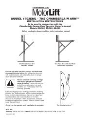
Fitting instructions for<br />
(Read instructions fully, before installing the door)<br />
Horizontal tracked doors<br />
supplied with ' <strong>Retractable</strong><br />
operating gear.<br />
All doors with retractable<br />
gear can be electrically<br />
operated using System '<br />
when the clearance above<br />
the opening is 150mm or<br />
more.<br />
(Dimensions throughout these<br />
instructions are in mm.<br />
Weatherstrip<br />
stiffener<br />
Link arm and<br />
weatherstrip<br />
assembly<br />
---r: -<br />
Roller<br />
spindle<br />
Springs<br />
and covers<br />
Locking bars<br />
(Double door shown)<br />
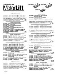
Pramearra.ngement<br />
BEHIND BRICKWORK<br />
2000 clear<br />
Ensure that the opening is prepared correctly to<br />
dimensions applicable to the door being fitted.<br />
50mm<br />
50mm min. timber head<br />
70mm<br />
BETWEEN BRICKWORK<br />
2000 clear<br />
70mm<br />
min, timber jambs<br />
70mm<br />
Opening Width<br />
f1'<br />
0'00'09 W'dth<br />
70mm<br />
OB- FIT-40510<br />
Garador Limited, Bunford Lane, Yeovii , Somerset BA20 2YA<br />
Tel: (01935) 443700 1935) 443744 CG 96/2<br />
III"'I!I-
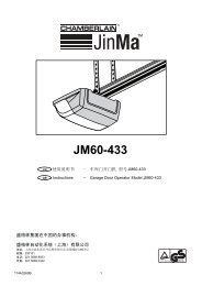
t'lease- C;;neGK-mat-yeu-navealltne<br />
parts before installation.<br />
Item<br />
Track hangar strap<br />
108-975<br />
Item<br />
Top weatherstrip<br />
108- 105-<br />
108-106- 1RP<br />
Item<br />
Item<br />
Plastic weatherstrip<br />
108- 127<br />
Link arm - G250-<br />
Weatherstrip<br />
G250-7 and 7L<br />
Spring anchor pin<br />
G250-<br />
Item<br />
t /<br />
Item<br />
P-clip<br />
01- PLT-00010<br />
Item<br />
Cable ties<br />
OF-CBL-07152<br />
I!r .m..<br />
'I."~ .'....... "II'''''r'<br />
Item<br />
Item<br />
Rubber stop<br />
OF-BMP-06690<br />
Track assembly<br />
108-971- 1 &2<br />
Top corner<br />
fixing plate<br />
Fixings supplied<br />
Item<br />
Item<br />
M6x50 Coach screw<br />
OH-SCW- 16385<br />
6==<br />
(QJ<br />
M6x40 Screw<br />
OH-SGW- 15640<br />
M6 Nut<br />
OH- NTS- 12910<br />
M6 Washer<br />
OH-WSH-21720<br />
Item<br />
M10Nut<br />
OH-NTS- 12970<br />
Clip<br />
OF-CLP-08363<br />
Item<br />
Qty<br />
2nuts/4 clips<br />
(9J<br />
(Q)
IX op er<br />
op erstrip<br />
and Bottom Pivot Bracket<br />
fig. 3.<br />
Top Roller Bracket<br />
(item 1)<br />
Bottom Pivot Bracket<br />
(item 4)<br />
Before commencing installation of the door, prepare the panel by fixing items 1<br />
Hex. HD self tapping screws (item 16) as illustrated in fig. 1 2 and 3.<br />
3 and 4 using the No.<br />
Fix Handles and Locking Bars at this stage<br />
TIMBER AND GRP DOORS<br />
FIxing<br />
Rear of Door o"<br />
Lock<br />
r \ Screw<br />
Handle<br />
*Adjustment .<br />
Bearing<br />
~~ l Handle Adjustment Nut<br />
Outside Handle<br />
*Handle Assembly prior to fitting<br />
WARNING:- If the handle is not adjusted correctly<br />
the result will be stiffness of the handle and lock<br />
mechanism.<br />
32mm - GRP<br />
34mm - Timber<br />
For addi60nal adjustment of the threaded shaft:-<br />
Remove the Adjustment Pin, adjust the shaft and<br />
re-fit the pin into the appropriate hole.<br />
STANDARD<br />
STEEL DOORS<br />
Outside Handle<br />
Handle Fixing Screw<br />
Lock Fixing Screw<br />
Lock & Keys<br />
Rear of Door<br />
Shaft Spacer<br />
Handle Bearing<br />
Inside Handle<br />
~<br />
Assembly<br />
.e':'S'i<br />
r<br />
Lock and Keys<br />
Lock Fixing Screw<br />
Handle F:xing Screw
, Place I. oor into Prepar?d. Opening<br />
FOR DOUBLE SIZE DOORS fig. 6<br />
16mm<br />
Set the door centrally into the frame opening<br />
leaving an equal 8mm clearance gap each<br />
side parallel to the frame , as fig. 6.<br />
Timber Frame<br />
Pack up the bottom of the door leaving a<br />
parallel 16mm clearance gap between the<br />
top of the door and frame head. it is<br />
important that this dimension is maintained as<br />
accurately as possible.<br />
8mm<br />
Drive a small nail into the frame , tight against<br />
the edges of the top weatherstrip (item 3) to<br />
prevent the door moving sideways.<br />
Packing<br />
. Fix Link<br />
Step<br />
Timber Frame<br />
Slide the link arm<br />
assembly (item 5) into<br />
the bottom pivot<br />
bracket (item 4) as<br />
illustrated by fig.6 and<br />
secure with clip (item<br />
22). Ensure the link<br />
arm is parallel to the<br />
side of the door panel<br />
then slide the<br />
weatherstrip between<br />
the link arm wall<br />
bracket and the<br />
timber jamb locating<br />
the four fixing holes.<br />
Step 2<br />
Note:<br />
It is important to<br />
maintain an equal<br />
overlap each side<br />
of the door<br />
Drill 7 off fixing holes<br />
3mm diameter through<br />
the link arm and<br />
weatherstrip holes into the<br />
timber frame as illustrated<br />
in fig 8.<br />
Link arm assembly<br />
Weatherstrip<br />
assembly<br />
(item 5)<br />
E-clip<br />
fig. 8<br />
(item 5)<br />
3) :<br />
Secure assembly using<br />
screw (item 17)<br />
c:J<br />
fig. 7<br />
Bottom pivot<br />
bracket (item 3)<br />
Drill holes
PUW:I-.-<br />
DOUBLE DOOR<br />
Position for<br />
stiffener<br />
(top holes)<br />
Top weatherstrip<br />
(item 3)<br />
Using the weatherstrip stiffener (item 6) determine<br />
the position of the stiffener and drill holes 3mm<br />
diameter through corresponding holes in the<br />
weatherstrip (item 5) into the timber frame. Secure<br />
using screws (item 17). See fig. 9.<br />
This point forms a pivot when the door is<br />
operated and is critical when the door is<br />
driven by an electric operator.<br />
Pre-drilled holes in the weatherstrip assembly<br />
(item 5) give accurate fixing locations for all items.<br />
Complete the fixing of the assembly using screws<br />
(item 16).<br />
SINGLE DOOR<br />
Position for stiffener<br />
(lower holes)<br />
fig. 9<br />
Where required (7' high doors), cut plastic<br />
weatherstrip (item 12) to the required length and<br />
fix to the timber frame with screw (item 16).<br />
Prepare and fix track assemblies<br />
With the components as shown in item 7, fix the rubber<br />
stop to the track end using bolt washer and nut (item 21).<br />
Holding the track assembly vertically, the jamb fixing<br />
angle uppermost and against the jamb, slide upwards<br />
and engage top roller of door in track and , with the fixing<br />
angle against the jamb, rotate track to the horizontal<br />
position. Allowing the front end of the track to rest on the<br />
roller, align the track so that it is both horizontal and<br />
square to the door. Fix the track at the rearward end<br />
temporarily, using a track hanger strap (item 8) attached<br />
to the hanger bracket with bolt, nut and washer (item 18)<br />
and fixed to a convenient roof joist or cross-tie with one<br />
screw (item 16).<br />
Ensure the roller at the front end is located centrally in<br />
and bearing on the bottom of the track (see inset) and fix<br />
track assembly to jamb as illustrated using two screws<br />
(item 17) and two washers (item 19).<br />
Drill and fix hanger straps in convenient intermediate<br />
positions using bolts , nuts and washers (item 18) and<br />
screws (item 16).<br />
The straps supplied can be bent, twisted or re-drilled to<br />
produce suitable brackets for either side wall or ceiling<br />
fixing to suit circumstances. Some suggested<br />
arrangements are illustrated.<br />
Repeat procedure fixing track to other side of door.<br />
Remove all wedges, nails and props , raise the door<br />
slowly and in the open position. SECURE DOOR BY<br />
CONVENIENT MEANS TO PREVENT ACCIDENTAL<br />
CLOSURE (wire ties etc.<br />
)r9<br />
Hangar bracket<br />
Bolt (item 21)
It spnngs an.<br />
With the door securely propped in the open position , attach spring anchor pin to link arm assembly (centre<br />
hole as shown) and secure with self locking nuts supplied (see instruction<br />
Step. 1' .<br />
Step 2<br />
Remove springs (item<br />
Place eye at one end of the spring over<br />
the hook on the spring anchor bracket<br />
nearest to the<br />
door panel.<br />
Using a cloth<br />
to protect your<br />
hands, grip the<br />
upper end of<br />
the spring<br />
firmly as close<br />
to the eye as<br />
possible and<br />
by stretching<br />
the spring<br />
upwards, hook<br />
the eye over<br />
the anchor pin<br />
on the link<br />
arm, locating<br />
the eye in the<br />
groove nearest<br />
the door.<br />
Link arm<br />
assembly<br />
Take inner<br />
cover tube<br />
slotted end<br />
down and clip<br />
over the spring.<br />
Slide tube<br />
downwards<br />
locating slot<br />
over the anchor<br />
bracket and fix<br />
with cable tie<br />
(item 14). Take<br />
outer cover tube<br />
slotted end up,<br />
clip over the<br />
inner tube and<br />
engage slot and<br />
hole over the<br />
anchor pin.<br />
Spring<br />
anchor<br />
bracket<br />
Spring anchor<br />
pin<br />
Spring anchor<br />
pin<br />
-P"<br />
E-clip<br />
(item 22)<br />
Fit second spring and<br />
covers when doors are<br />
supplied with four<br />
springs. Finally secure<br />
springs on the anchor<br />
pin using special clip<br />
(item 22) which<br />
springs into the groove<br />
on the end of the pin.<br />
Final check, operating and spring adjustment<br />
Open the door and insure that the door is square to<br />
the opening, that rollers are located centrally in the<br />
track and that the weight of the door rests equally on<br />
each track. Adjust track hanger brackets if necessary<br />
and fix firmly in required positions.<br />
Try the door up and down a few times. If the<br />
instructions have been followed correctly the door will<br />
operate smoothly.<br />
For their size, retractable Garadors move extremely<br />
freely. When opening, move the door steadily to the<br />
fully open position. DO NOT throw the door upwards.<br />
Lubricate inside tracks , all pivot points and cable<br />
latches. To ensure continued ease of operation<br />
lubricate periodically.<br />
On SINGLE DOORS , fit the pull cord and grip into the<br />
hole drilled in the crossbracing at the rear of the door.<br />
Should it be necessary to increase or decrease the<br />
spring power, adjustment can be made by<br />
repositioning the spring anchor pins in the additional<br />
holes provided at the ends of the link arms. Raise the<br />
door to the fully open position and prop. Remove the<br />
springs and reposition Hie anchor pins one side at a<br />
time , progressively until a satisfactory balance is<br />
obtained.<br />
Reduce<br />
spring power<br />
Increase<br />
spring power<br />
pin and self<br />
locking nut<br />
A weatherstrip for the top edge of the door is not<br />
provided but can be fitted as illustrated , projecting<br />
max. 20mm below the frame head.<br />
70x70 frame<br />
(recommended)<br />
70x50 frame<br />
(minimum)<br />
Door<br />
Door