Enclosures
Enclosures
Enclosures

You also want an ePaper? Increase the reach of your titles
YUMPU automatically turns print PDFs into web optimized ePapers that Google loves.
3-1<br />
Crouse-Hinds ®<br />
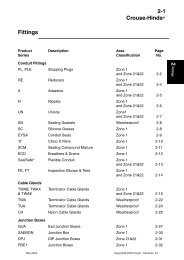
Junction Boxes<br />
Product Description Area Page<br />
Series Classification No.<br />
Junction Boxes<br />
GUBA Junction Boxes Zone 1 3-2<br />
EJBA Junction Boxes Zone 1 3-6<br />
JBDC Junction Boxes Zone 21&22 3-9<br />
JBEC Junction Boxes Zone 1 3-9<br />
JBWC Junction Boxes Weatherproof 3-9<br />
PBE Junction Boxes Zone 1<br />
and Zone 21&22 3-18<br />
3 <strong>Enclosures</strong><br />
Marshalling Boxes<br />
JBD Marshalling Boxes Zone 21&22 3-12<br />
JBE Marshalling Boxes Zone 1 3-12<br />
JBI Marshalling Boxes Zone 0 3-12<br />
JBW Marshalling Boxes Weatherproof 3-12<br />
Junction Boxes and <strong>Enclosures</strong><br />
GHG74 Junction Boxes & <strong>Enclosures</strong> Zone 1<br />
and Zone 21&22 3-20<br />
May 2003<br />
Copyright© 2003 Cooper Industries, Inc
3-2<br />
Crouse-Hinds ®<br />
GUBA<br />
Junction Boxes<br />
Flameproof, Exd, IIC, IP66<br />
Zone 1<br />
3 <strong>Enclosures</strong><br />
Application:<br />
GUBA series junction boxes are<br />
used in threaded rigid conduit and<br />
cable systems in hazardous areas<br />
• To function as a splice box, pull<br />
box or equipment device enclosure<br />
• Indoors and outdoors<br />
Features:<br />
• Threaded construction<br />
throughout permits use in<br />
hazardous areas<br />
• Wide variety of conduit entry<br />
arrangements<br />
• Covers are sealed with "O" ring<br />
gasket<br />
Standard Materials:<br />
• Bodies and covers - Cast<br />
copper-free aluminium<br />
Standard Finishes:<br />
• Natural<br />
Options:<br />
• Cast iron. Bodies and<br />
covers....Add suffix WOD<br />
• Corrosion Resistant Grey<br />
Polyurethane finish - consult<br />
factory<br />
• Drilling and tapping to suit<br />
application eg. metric and imperial<br />
conduit, NPT and BSP pipe<br />
threads. (Metric threads standard)-<br />
Information on request.<br />
Various cover types.<br />
• Terminals can be supplied with<br />
junction boxes to specification<br />
Glass windows can be added<br />
• Dome covers can be added<br />
Compliances:<br />
• Certificate of Compliance<br />
No. Ex 262 for GUBA01,<br />
GUBA1440, GUBA1100,<br />
GUBA1103 to AS2480<br />
No. Ex 324 for GUBA02, GUBA726<br />
to AS2480<br />
• IP66 to AS1939<br />
Ordering Information:<br />
1. Refer to Table 1 (next page) to determine whether a GUBA01 or<br />
GUBA02 is required .<br />
2. Specify exact number, type, size and location of all entries, taking care<br />
not to exceed the maximum number of entries given in<br />
Table 1.<br />
3. Order the type of cover required separately - see section on Threaded<br />
Covers for GUBA Junction Boxes (page 3-4)<br />
Examples:<br />
1. GUBA01 with:<br />
2x25mm entries in top<br />
2x25mm entries in bottom<br />
2x25mm entries in left side<br />
1x25mm entry in right side<br />
2. GUBA02 with:<br />
2x1 1/4" BSP entries in top<br />
2x1 1/4" BSP entries in bottom<br />
1x2" Imp entry in left side<br />
1x50mm entry in right side<br />
4x20mm entries in back<br />
May 2003<br />
Copyright© 2003 Cooper Industries, Inc
3-3<br />
Crouse-Hinds ®<br />
Ordering Information<br />
Table 1 Maximum Number of Entries:<br />
Metric 20mm 25mm 32mm 40mm 50mm<br />
Imp.Conduit 3/4" 1" 1-1/4' 1-1/2" 2"<br />
NPT & BSP 1/2" 3/4" 1" 1-1/4" 1-1/2"<br />
Catalogue No.<br />
Top & Bottom<br />
GUBA01 6 5 3 2 1<br />
GUBA02 10 8 4 3 2<br />
Sides<br />
GUBA01 6 5 − − −<br />
GUBA02 8 7 4 3 2<br />
Back<br />
GUBA01 3 3 − − −<br />
GUBA02 4 4 − − −<br />
3 <strong>Enclosures</strong><br />
Dimensions: (mm)<br />
Catalogue External Dim. Internal Dim. Mounting Dim. No. of Weight<br />
Number A B C D E F G H X Y Mtg. Feet Kg<br />
GUBA01 195 220 175 146 146 130 107 76 195 145 2 4.2<br />
GUAB02 253 298 233 204 224 185 135 76 264 216 2 8.1<br />
May 2003<br />
Copyright© 2003 Cooper Industries, Inc
3-4<br />
Crouse-Hinds ®<br />
GUBA<br />
Threaded covers<br />
Flameproof, Exd, IIB or IIC, IP66<br />
Zone 1<br />
3 <strong>Enclosures</strong><br />
Application:<br />
GUBA threaded covers are used<br />
with GUBA boxes in control systems<br />
in hazardous areas<br />
Indoors and outdoors<br />
• In three categories:<br />
Flat - for normal use; furnished with<br />
standard GUBA boxes<br />
Glass window - to provide visibility<br />
of meter indications when used to<br />
enclose meters<br />
Dome - for increasing volume of<br />
GUBA to make it easier to splice and<br />
pull large conductors<br />
Features:<br />
• Dome - more suitable for use<br />
when splices of heavy conductors<br />
are made and enclosed, since the<br />
conductors may be pulled in with the<br />
ends outside the box. After the<br />
splices are made, they do not have<br />
to be crowded back into the box<br />
• Glass window - has maximum<br />
diameter glass to give best visibility.<br />
In selecting, the diameter of the<br />
meter face should match or be<br />
slightly smaller than window<br />
diameter.<br />
• Supplied with O-ring gaskets<br />
Standard Materials:<br />
Copper-free aluminium<br />
• O-ring gasket ------------Neoprene<br />
GUBA flat cover GUBA glass cover GUBA<br />
(Exd IIB only)<br />
Dome Cover<br />
Standard Finish:<br />
• Natural<br />
Options:<br />
• Corrosion Resistant Powder<br />
polyester................consult factory<br />
Cover information:<br />
*Compliances:<br />
• Flat cover GUBA0101 and Glass<br />
Window Cover GUBA0110, .............<br />
..........................................Group IIC<br />
• Dome Covers GUBA714,<br />
GUBA7110 and GUBA726...............<br />
..........................................Group IIB<br />
Glass window Dome Cover<br />
Body Size Flat Cover Cover Cat.No. Cat.No. (100mm)<br />
Cat No.<br />
GUBA01 GUBA0101 GUBA0110 GUBA714<br />
Dimensions: GUBA with dome covers (mm)<br />
Dome Covers<br />
Cat.No. H J K M<br />
GUBA714 127mm 70mm 106mm 101mm<br />
Please Refer Page 3-3<br />
for dimensions<br />
May 2003<br />
Copyright© 2003 Cooper Industries, Inc
3-5<br />
Crouse-Hinds ®<br />
GUBA<br />
Instrument<br />
Housings<br />
Flameproof, Exd, IIC, IP66<br />
Zone 1<br />
Application:<br />
GUBA instrument housings are used<br />
• To enclose ammeters, voltmetres,<br />
wattmeters, varmeters, power-factor<br />
meters, tachometer or other<br />
indicating devices<br />
• In specific hazardous atmospheres<br />
such as encountered in oil refineries,<br />
chemical plants, paint and varnish<br />
manufacturing plants<br />
Features:<br />
• Threaded covers have glass<br />
windows for viewing scale, dial or<br />
setting of enclosed instrument<br />
• Mounting plates, brackets or pillars<br />
for mounting a wide variety of<br />
instruments are available<br />
Standard Materials:<br />
Body - Copper-free aluminium<br />
Cover - Copper-free aluminium<br />
• Window - Toughened<br />
Standard Finishes:<br />
• Light Grey Corrosion Resistant<br />
Polyurethane<br />
Options:<br />
• Other conduit hub sizes and<br />
arrangements can be furnished<br />
• Meter - 90° quadrant or 250° long<br />
scale<br />
Compliances:<br />
• Certificate of Compliance No. Ex<br />
262<br />
to AS2480<br />
• IP66 to AS1939<br />
Notes:<br />
1. Accommodates any make of meter<br />
styles 96Q or 96L<br />
2. Instrument to be used must be<br />
specified by make, complete<br />
identification data and dimensions<br />
Ordering Information:<br />
Basic Entry<br />
Housing Size Position Cat. No.<br />
GUBA01 25mm Top GUBA 1103-1-20<br />
GUBA01 25mm Bottom GUBA 1103-1-02<br />
Dimensions:(mm)<br />
A B C D E F G<br />
195 145 93 140 135 77 145<br />
3 <strong>Enclosures</strong><br />
May 2003<br />
Copyright© 2003 Cooper Industries, Inc
3-6<br />
Crouse-Hinds ®<br />
EJBA<br />
Junction Boxes<br />
and <strong>Enclosures</strong><br />
Flameproof, Exd, IIB or IIC (H2), IP66<br />
Zone 1<br />
3 <strong>Enclosures</strong><br />
Application:<br />
EJBA junction boxes are used in<br />
areas made hazardous by the<br />
presence of flammable liquids,<br />
gases and vapours, indoors or<br />
outdoors<br />
As a junction or draw-in box<br />
As a marshalling box<br />
• To enclose equipment and control<br />
devices, relays, contactors and / or<br />
instruments<br />
• To house custom-built control<br />
panels. See section 4 Industrial<br />
Control under EJBA Custom Built<br />
Control Panels<br />
Features:<br />
• External flange with machined<br />
joint cover opening provides<br />
maximum opening for pulling cables<br />
or mounting equipment<br />
• Body walls have sufficient<br />
thickness to allow for drilled and<br />
tapped entries<br />
• Special one piece hollow<br />
neoprene gasket designed to fully<br />
compress to ensure metal to metal<br />
contact of cover and body for<br />
explosion proof integrity while giving<br />
an IP66 weatherproof seal to<br />
AS1939<br />
• The sealing gasket is placed<br />
inward from the cover bolt holes, to<br />
prevent ingress of any moisture<br />
• Hinges provide convenient and<br />
easy access for inspection,<br />
maintenance and systems changes.<br />
Integral cast hinges are fitted as<br />
standard on EJBA464, EJBA783<br />
and EJBA786. Aluminium hinges<br />
are also provided as standard on<br />
EJBA211710 up to EJBA361810.<br />
Optional stainless steel hinges are<br />
available for sizes EJBA886 up to<br />
EJBA161608<br />
• Entries can be drilled and tapped<br />
to customer requirements<br />
EJBA Enclosure with optional hinged cover<br />
and standard neoprene cover gasket<br />
Standard Materials:<br />
• Body and cover - Copper free<br />
aluminium<br />
Cover Screws - Stainless steel<br />
• Standard Hinges - Copper free<br />
aluminium. Optional Hinges - Stainless<br />
steel<br />
• Gasket - Neoprene<br />
Standard Finish:<br />
• EJBA 2424, 2418, 211710 cover<br />
Corrosion Resistant Grey<br />
Polyurethane, remainder Natural<br />
Options:<br />
• Hinges for sizes EJBA886 up to<br />
EJBA161608...............add suffix S598<br />
• Mounting Plate for devices, relays<br />
etc...................................add suffix MP<br />
• Corrosion Resistant Grey Polyurethane<br />
finish - consult factory......add suffix S752<br />
Drill and tap entries .................. specify<br />
Captive cover screws ............... specify<br />
• Gas Group IIC............................refer to<br />
following page for available sizes and<br />
specify when ordering<br />
Compliances:<br />
• Certificate of Compliance Nos<br />
EJBA121208 to EJBA361810... Ex 407<br />
EJBA464 to EJBA9166 .............Ex 459<br />
• IP66 to AS1939<br />
* Consult factory for EJBA783 and 786<br />
May 2003<br />
Copyright© 2003 Cooper Industries, Inc
3-7<br />
Crouse-Hinds ®<br />
Ordering Information<br />
Size Ranges & Gas Group:<br />
Nominal inside dimensions: (mm)<br />
Cat. No. Width Height Depth Gas Group<br />
EJBA464 150 100 100 IIB<br />
EJBA783 200 170 70 IIB or IIC (H2)<br />
EJBA786 200 170 140 IIB or IIC (H2)<br />
EJBA886 200 200 150 IIB or IIC (H2)<br />
EJBA1286 200 300 150 IIB or IIC (H2)<br />
EJBA9166 228 400 150 IIB or IIC (H2)<br />
EJBA121208 300 300 200 IIB or IIC (H2)<br />
EJBA161608 400 400 200 IIB or IIC (H2)<br />
EJBA211710 440 545 255 IIB or IIC (H2)<br />
EJBA241810 450 600 255 IIB or IIC (H2)<br />
EJBA242410 600 600 255 IIB or IIC (H2)<br />
EJBA361810 450 915 255 IIB<br />
Mounting Plate<br />
MP0406<br />
MP0708<br />
MP0708<br />
MP0808<br />
MP1208<br />
MP0916<br />
MP1212<br />
MP1616<br />
MP2117<br />
MP2418<br />
MP2424<br />
MP3618<br />
3 <strong>Enclosures</strong><br />
Gasket Detail:<br />
Cross section<br />
of corner<br />
Bolted cover &<br />
body assembled<br />
Note:<br />
All drilling and tapping of entries etc must be carried out by the<br />
manufacturer to ensure certification requirements are not breached.<br />
While mounting of devices such as relays etc can be carried out in the<br />
future if the enclosure is provided with a mounting plate, care should be<br />
taken with devices which are likely to raise the surface temperature of the<br />
enclosure. If in doubt contact the factory for further information.<br />
May 2003<br />
Copyright© 2003 Cooper Industries, Inc
3-8<br />
Crouse-Hinds ®<br />
Ordering Information<br />
3 <strong>Enclosures</strong><br />
Dimensions:(mm)<br />
Cat.No. A B C D E F Mtg<br />
Screws<br />
EJBA464 215 165 122 135 145 150 M6<br />
EJBA783 265 225 87 115 230 192 M8<br />
EJBA786 265 225 87 170 230 192 M8<br />
EJBA886 280 280 180 230 140 280 M8<br />
EJBA1286 280 380 175 225 168 305 M12<br />
EJBA9166 305 485 175 225 242 325 M12<br />
EJBA464-EJBA886<br />
Cat.No. A B C D E F Mtg<br />
Screws<br />
EJBA121208 415 415 230 285 143 395 M12<br />
EJBA161608 516 516 230 285 242 505 M12<br />
EJBA211710 654 50 323 355 300 610 M12<br />
EJBA241810 595 750 295 350 413 556 M12<br />
EJBA242410 750 750 295 350 413 708 M12<br />
EJBA361810 608 1065 295 365 718 585 M16<br />
Larger sizes are available upon request, pending on qty<br />
EJBA1286 - EJBA161608<br />
EJBA211710 - EJBA242410<br />
May 2003<br />
Copyright© 2003 Cooper Industries, Inc
3-9<br />
Crouse-Hinds ®<br />
JBEC Junction Boxes<br />
JBDC Junction Boxes<br />
JBWC Junction Boxes<br />
Increased Safety, Exe, IP66/67, IIC<br />
Zone 1<br />
Combustible Dust<br />
Zone 21&22<br />
Weatherproof<br />
Application:<br />
• JBEC junction boxes are used to<br />
house non-arcing equipment, such as<br />
terminals (Exe certified) in Zone 1<br />
hazardous locations on drilling and<br />
production platforms, petroleum<br />
refineries, chemical plants and other<br />
process facilities where similar<br />
hazards exist<br />
• JBDC Junction boxes are used in<br />
Combustible Dust hazardous<br />
locations such as grain handling<br />
plants, cotton gins, flour mills and<br />
other process facilities where similar<br />
hazards exist<br />
• JBWC junction boxes are used to<br />
house components, such as<br />
terminals, relays, switches, where a<br />
corrosion, heat and water resistant<br />
enclosure is required for protection of<br />
electrical equipment against the harsh<br />
effects of weather<br />
To terminate or join power cables<br />
• To marshall small cables for<br />
connection to large multi-core or<br />
instrumentation cables<br />
• For use in damp, wet and corrosive<br />
locations<br />
Features:<br />
• Robust cast aluminium enclosures<br />
to stand up to harsh environments.<br />
• Certified terminals installed to<br />
customer requirements<br />
• Mounting pads for flexibility of<br />
terminal rail installation<br />
• Drilled and tapped entries for direct<br />
installation of cable glands and conduit.<br />
Captive cover screws<br />
• O-ring cover seal insures water<br />
tightness<br />
Standard Materials:<br />
• Body and Cover - Cast copper-free<br />
aluminium.<br />
Cover Screws - Stainless Steel.<br />
• Gasket - Neoprene.<br />
Standard Finish:<br />
• Natural.<br />
Options:<br />
• Pre-drilled and tapped or clearance<br />
entries.<br />
• Entries fitted with PLE sealing<br />
plugs.<br />
• Traffolite identification label.<br />
• JBWC111 can be supplied as<br />
custom-built control station to<br />
customer requirements, consult<br />
factory.<br />
Compliances:<br />
• SAA Certification to AS2380.<br />
Type of protection Exe.<br />
• AS2236 Electrical Equipment for<br />
Explosive atmospheres.....Dust<br />
Excluding Ignition Proof.<br />
• Degrees of Protection IP66/67 to<br />
AS1939<br />
• Certificate of Compliance No.<br />
JB❉C111 - Ex3177x<br />
JBEC2❉1 - Ex1000x<br />
JBDC2❉1 - Ex776<br />
3 <strong>Enclosures</strong><br />
May 2003<br />
Copyright© 2003 Cooper Industries, Inc
3-10<br />
Crouse-Hinds ®<br />
Ordering Information<br />
1. Determine quantity and size of terminals and entries required.<br />
2. Confirm requirements are within maximum limits outlined in tables 1 and 2.<br />
3. Specify catalogue number as outlined below.<br />
4. Specify details of options if required.<br />
Catalogue No. make-up:<br />
3 <strong>Enclosures</strong><br />
Construction<br />
JBEC - Exe<br />
JBDC - D.I.P.<br />
JBWC - Weatherproof<br />
JBEC 111 - 10 A - 3 B 1 M<br />
Size<br />
111<br />
221<br />
222<br />
Terminal Size<br />
Quantity of<br />
Terminals<br />
Code Size mm 2<br />
A - 2.5<br />
B - 4.0<br />
C - 6.0<br />
D - 10.0<br />
E - 16.0<br />
Quantity of<br />
Entries<br />
Face<br />
T - Top<br />
B - Bottom<br />
L - Left<br />
R - Right<br />
A - Equally<br />
over all sides<br />
Entry Thread Form<br />
M - Metric<br />
N - NPT<br />
Entry Size<br />
Code Metric NPT<br />
1 - M20 1/2”<br />
2 - M25 3/4”<br />
3 - M32 1”<br />
4 - M40 1 1/4”<br />
5 - M50 1 1/2”<br />
Example:<br />
The catalogue number detailed above specifies a JBEC111 Exe Increased Safety enclosure complete<br />
with 10 x 2.5 mm 2 terminals and 3 x M20 entries of the bottom face.<br />
Table 1<br />
Maximum Terminals<br />
Size Code A B C D E<br />
Size (mm 2 ) 2.5 4.0 6.0 10.0 16.0<br />
Maximum Quantity<br />
JB❉C111 14 10 10 8 7<br />
JB❉C22❉ 20 15 11 10 9<br />
Options:<br />
Combinations of terminal sizes - Available on request, consult factory.<br />
Table 2<br />
Maximum Entries per Side<br />
Entry Size Code 1 2 3 4 5<br />
Entry Size Metric M20 M25 M32 M40 M50<br />
Entry Size NPT 1/2” 3/4” 1” 1 1/4” 1 1/2”<br />
Maximum Quantity<br />
JB❉C111 5 4 2 1 1<br />
JB❉C22❉ 6 5 3 2 1<br />
Options:<br />
Entries are configured using Crouse-Hinds Terminator TM Cable Glands.<br />
Combinations are available on request, consult factory.<br />
May 2003<br />
Copyright© 2003 Cooper Industries, Inc
3-11<br />
Crouse-Hinds ®<br />
Ordering Information<br />
Dimensions: (mm)<br />
JB❉C111<br />
3 <strong>Enclosures</strong><br />
JB❉C22❉<br />
Cat. No. Nominal overall Dimensions (mm)<br />
dimensions A B C D E F<br />
JB❉C221 200 x 200 x 120 191 191 120 96 155 218<br />
JB❉C222 200 x 200 x 160 191 191 160 96 155 218<br />
May 2003<br />
Copyright© 2003 Cooper Industries, Inc
3-12<br />
Crouse-Hinds ®<br />
JBE Marshalling Boxes<br />
JBD Marshalling Boxes<br />
JBI Marshalling Boxes<br />
JBW Marshalling Boxes<br />
Increased Safety, Exe, IP66/67, IIC<br />
Zone 1<br />
Combustible Dust, IP66/67<br />
Zone 21 & 22<br />
Intrinsic Safety, Exi, IP66/67, IIC<br />
Zone 0 & 1<br />
Weatherproof, IP/67<br />
3 <strong>Enclosures</strong><br />
Application:<br />
• JBE and JBI Marshalling boxes are<br />
used in Zone 1 hazardous locations<br />
on drilling and production platforms,<br />
petroleum refineries, chemical plants<br />
and other process facilities where<br />
similar hazards exist<br />
• JBD Marshalling boxes are used in<br />
Combustible Dust Hazardous<br />
locations such as grain handling<br />
plants, cotton gins, flour mills and<br />
other process facilities where similar<br />
hazards exist<br />
• JB❉ series marshalling boxes<br />
provide protection for electrical<br />
equipment and devices from<br />
mechanical hazards, and moisture<br />
and dust ingress to:<br />
• For Exe applications to house nonarcing<br />
equipment such as Exe terminals<br />
• Marshall process instrumentation<br />
cables<br />
Terminate or join power cables<br />
• Marshall small cables for<br />
connection to large multi-core cables<br />
In damp, wet and corrosive locations<br />
• For DIP and Weatherproof<br />
applications to house electrical<br />
equipment such as relays, contactors<br />
and control devices<br />
Features:<br />
• Robust metallic enclosures to stand<br />
up to harsh environments<br />
• External mounting feet to ensure<br />
weatherproof integrity<br />
• Top slotted mounting feet to ease<br />
installation<br />
Hinged removable front cover<br />
Captive cover screws<br />
• Reliable corrosion resistant<br />
stainless steel hinges<br />
• Removable gland plates enable onsite<br />
drilling of gland entries<br />
• Standard terminal rails accept most<br />
common sizes of rail mounted terminals<br />
• 10mm dia internal and external<br />
earth studs<br />
• Corrosion resistant 316 Stainless<br />
steel 3mm thick gland plates on JBE,<br />
JBI, and JBW boxes<br />
Standard Size Ranges:<br />
Cat. No. Nominal overall<br />
dimensions (mm)<br />
JB❉22 270 x 200 x 150<br />
JB❉33 370 x 300 x 200<br />
JB❉54 500 x 400 x 200<br />
JB❉75 700 x 500 x 200<br />
JB❉96 900 x 600 x 300<br />
Standard Materials:<br />
• Enclosure<br />
JB❉❉❉SS<br />
316 Stainless Steel 1.6mm thick<br />
JB❉❉❉MS<br />
Mild Steel 2mm thick<br />
• Gland Plates<br />
JBE, JBI, JBW<br />
316 Stainless Steel 3mm thick<br />
JBD<br />
Copper free aluminium 10mm thick<br />
• External Hardware - Stainless Steel<br />
• Hinges - Stainless Steel<br />
• Gaskets - Neoprene rubber<br />
Standard Finish:<br />
• Mild Steel - Zincalume plated, grey<br />
powder polyester coated<br />
• Stainless Steel - Electropolished<br />
• Gland plates - 2B Mechanical polish<br />
Options:<br />
• External stainless steel identification<br />
label mounting bracket<br />
• Glass window in cover on JBD and<br />
JBW boxes only<br />
• Breather drain assembly fitted to<br />
bottom gland plate<br />
• Available as custom-built control unit.<br />
See section 4 Industrial control, under<br />
Custom-Built Control Panels<br />
Compliances:<br />
• AS2380 - Electrical Equipment for<br />
Explosive Atmospheres ... Increased<br />
Safety<br />
• AS2236 Electrical Equipment for<br />
Explosive Atmospheres - Dust<br />
Excluding Ignition Proof<br />
• AS1939 - Degrees of Protection<br />
IP66<br />
• Certificate of Compliance<br />
JBE & JBI - Ex630X<br />
JBD - Ex667<br />
May 2003<br />
Copyright© 2003 Cooper Industries, Inc
3-13<br />
Crouse-Hinds ®<br />
Features<br />
Captive Cover Screws<br />
3 <strong>Enclosures</strong><br />
Terminals fitted during assembly<br />
to customer requirements<br />
Cover mounted gasket minimises<br />
potential of damage during installation<br />
Padlock facility provided<br />
Large area gland plate opening<br />
Hinge design permits cover removal and<br />
incorporates elongated pin slots to<br />
ensure uniform seal contact<br />
Removable label mounting<br />
bracket enables labels to be<br />
affixed with screws, without<br />
effecting the enclosure IP rating<br />
Slotted top<br />
mounting foot<br />
simplifies installation<br />
May 2003<br />
Copyright© 2003 Cooper Industries, Inc
3-14<br />
Crouse-Hinds ®<br />
Ordering Information<br />
1. Determine quantity and size of terminals required.<br />
2. For Exe applications compare requirements to table below for maximum number of terminals in JBE box.<br />
3. Select enclosure size to accommodate quantity of terminals required. Consult factory if necessary.<br />
4. Specify catalogue number as outlined below.<br />
5. For other requirements refer to Ordering Specification Sheet on page 3-17.<br />
3 <strong>Enclosures</strong><br />
Catalogue No. make-up:<br />
JBE 33 SS - 3GP - 20 A - 8 B 1 M<br />
Construction<br />
JBE - Exe<br />
JBD - DIP<br />
JBI - Exi<br />
JBW - Weatherproof<br />
Enclosure Size<br />
22 - 270x200x150<br />
33 - 370x300x200<br />
54 - 500x400x200<br />
75 - 700x500x200<br />
96 - 900x600x300<br />
Enclosure Material<br />
MS - Mild Steel<br />
SS - Stainless Steel<br />
Gland Plates<br />
1GP - Bottom only<br />
3GP - Sides & Bottom<br />
Quantity of<br />
Terminals<br />
Terminal Size<br />
Code Size mm 2<br />
A - 2.5<br />
B - 4<br />
C - 6<br />
D - 10<br />
E - 16<br />
G - 35<br />
H - 70<br />
Quantity of<br />
Entries<br />
Gland Plate<br />
B - Bottom<br />
L - Left<br />
R - Right<br />
Entry Thread Form<br />
M - Metric<br />
N - NPT<br />
Entry Size<br />
Code Metric NPT<br />
1 - M20 1/2”<br />
2 - M25 3/4”<br />
3 - M32 1”<br />
4 - M40 1 1/4”<br />
5 - M50 1 1/2”<br />
Example:<br />
Note:<br />
The catalogue number detailed above specifies a JBE Exe Increased Safety enclosure<br />
370x300x200mm stainless steel, complete with bottom and side gland plates, 20 x 2.5 mm 2<br />
terminals and 8 x M20 entries on the bottom gland plate.<br />
To specify combinations of different terminal and entry sizes, include additional code groups within<br />
the catalogue number separated by a dash (-), i.e. JBE33SS-3GP-10A-5B-8B1M-1B2M<br />
Maximum Number of Terminals in JBE Exe Box:<br />
Standard Terminals<br />
Power Application at Maximum Rated Current<br />
Instrumentation<br />
Circuit Current<br />
Cat. A B C D E G H A<br />
No. 2.5mm 2 4.0mm 2 6.0mm 2 10.0mm 2 16.0mm 2 35.0mm 2 70.0mm 2 2.5mm 2<br />
JBE22 26 20 19 17 17 10 9 34<br />
JBE33 57 46 44 39 38 24 23 100<br />
JBE54 72 58 57 49 48 31 30 135<br />
JBE75 85 75 80 61 61 39 39 290<br />
JBE96 112 91 89 75 75 49 50 380<br />
Note 1:<br />
Note 2:<br />
Note 3:<br />
Limitations apply on terminal populations within Exe enclosures to ensure maximum power<br />
dissipation limits are not exceeded. Terminal populations can therefore increase where terminal loads are<br />
less than the maximum rated. Consult factory for details.<br />
The maximum number of terminals outlined for instrumentation circuit currents are recommended as<br />
a practical limit to ensure generous wiring space is available. Larger quantities of terminals can be provided.<br />
Large power terminal - Available on request, consult factory.<br />
Combinations of different terminal sizes - Available on request, consult factory<br />
May 2003<br />
Copyright© 2003 Cooper Industries, Inc
3-15<br />
Crouse-Hinds ®<br />
Ordering Information<br />
Dimensions: (Nominal i.e. + 2mm)<br />
A B C D E F H J<br />
JB❉22 270 200 155 128 230 240 150 80<br />
JB❉33 370 300 205 178 330 340 250 130<br />
JB❉54 500 400 205 178 460 440 350 130<br />
JB❉75 700 500 205 178 660 540 450 130<br />
JB❉96 900 600 305 278 860 640 550 230<br />
3 <strong>Enclosures</strong><br />
May 2003<br />
Copyright© 2003 Cooper Industries, Inc
3-16<br />
Crouse-Hinds ®<br />
Example Configurations<br />
Multiple Terminal Rails<br />
Side and Bottom Gland Plates<br />
Terminal Rail with<br />
Isolated Screen Terminal Bar<br />
Bottom Gland Plate Only<br />
3 <strong>Enclosures</strong><br />
Terminal Rail with Ducting<br />
Side and Bottom Gland Plates<br />
Power Terminals<br />
Bottom Gland Plate Only<br />
May 2003<br />
Copyright© 2003 Cooper Industries, Inc
Ordering Specification Sheet<br />
For special requirements which are outside the standard<br />
catalogue number system, please provide all details and a<br />
layout sketch on a copy of this ordering specification sheet.<br />
3-17<br />
Crouse-Hinds ®<br />
Identification No.: ................................................................................................... Quantity: ...................................<br />
Construction:<br />
JBE - Exe....................❏<br />
JBD - DIP.....................❏<br />
JBI - Exi.....................❏<br />
JBW - Weatherproof....❏<br />
Enclosure Size:<br />
270 x 200 x 150mm......❏<br />
370 x 300 x 200mm......❏<br />
500 x 400 x 200mm......❏<br />
700 x 500 x 200mm......❏<br />
900 x 600 x 300mm......❏<br />
Material:<br />
Stainless Steel...........❏<br />
Mild Steel...................❏<br />
Gland Plates:<br />
Bottom Only...............❏<br />
Sides & Bottom..........❏<br />
Label Bracket:<br />
Required........................❏<br />
3 <strong>Enclosures</strong><br />
Left Entry Detail<br />
Right Entry Detail<br />
Terminal Sizes and Quantity:<br />
Size<br />
Qty<br />
........................ ....................<br />
........................ ....................<br />
........................ ....................<br />
........................ ....................<br />
........................ ....................<br />
Bottom Entry Detail<br />
Identification Label:<br />
Required ........................❏<br />
Label Detail:...........................<br />
................................................<br />
................................................<br />
................................................<br />
................................................<br />
Terminal Numbering: ...........................................................................................................................................................<br />
................................................................................................................................................................................................<br />
Terminal Grouping and Linking: .........................................................................................................................................<br />
................................................................................................................................................................................................<br />
................................................................................................................................................................................................<br />
Other Requirements: ...........................................................................................................................................................<br />
................................................................................................................................................................................................<br />
................................................................................................................................................................................................<br />
May 2003<br />
Copyright© 2003 Cooper Industries, Inc
3-18<br />
Crouse-Hinds ®<br />
PBE<br />
Junction Boxes<br />
Increased Safety, Exe, IIC, IP66/67<br />
Zone 1<br />
Combustible Dust<br />
Zone 21 & 22<br />
3 <strong>Enclosures</strong><br />
Application:<br />
PBE Junction boxes are used:<br />
• T o house non-arcing equipment,<br />
such as terminals (Exe certified)<br />
• In Zone 1 Hazardous locations on<br />
drilling and production platforms,<br />
petroleum refineries, chemical<br />
plants and other process<br />
facilities where similar hazards exist<br />
To terminate or join power cables<br />
• To marshall small cables for<br />
connection to large multi-core<br />
cables<br />
• To marshall process<br />
instrumentation cables<br />
• In damp, wet and corrosive<br />
locations<br />
Features:<br />
• High impact strength and<br />
corrosion resistant plastic<br />
enclosures<br />
• Supplied with Exe certified<br />
terminals<br />
• Unique one piece terminal rail<br />
assembly is easily removed to give<br />
clear access for cable termination<br />
• Terminals stand proud for ease of<br />
wire connection<br />
• Lowered top profile improves<br />
wiring access to terminals<br />
• Elevated bottom face on<br />
enclosure base provides large area<br />
for cable entries<br />
• Entries for cable glands can be<br />
drilled on site for increased<br />
flexibility<br />
• Entries drilled as clearance holes<br />
to accommodate metric or NPT<br />
cable glands<br />
• Optional earth rail with earth<br />
terminals<br />
• Optional brass flange for drilled<br />
and tapped entries<br />
Standard Materials:<br />
• Base and cover - high impact<br />
strength corrosion resistant Fibre-<br />
Glass Reinforced Polyester<br />
• Gaskets - Two component<br />
polyurethane foam<br />
• External hardware - Stainless<br />
steel<br />
• Flange for drilled and tapped<br />
entries - Brass/natural finish<br />
Electrical Ratings:<br />
• Terminals rated up to 690V AC<br />
Compliances:<br />
• AS2380-6 Electrical Equipment<br />
for Explosive Atmospheres -<br />
Explosive protection techniques,<br />
Part 6 Increased safety<br />
• AS1939 - Degrees of protection<br />
- lP66/67<br />
• Certificate of compliance No.<br />
- AUS EX1431X<br />
- PTB 99 ATEX 1044<br />
Dimensions:<br />
May 2003<br />
Copyright© 2003 Cooper Industries, Inc
3-19<br />
Crouse-Hinds ®<br />
Ordering Information<br />
1. Determine quantity and size of terminals required<br />
2. Determine quantity and size of earth terminals required and then select quantity of earth rails<br />
3. Compare requirements to Table 1 below for maximum number of terminals in PBE box<br />
4. Select enclosure size to accommodate quantity of terminals required. Consult factory if necessary.<br />
5. Select options as required.<br />
Catalogue No. Make-Up:<br />
PBE 12 - 20 A - 1R 12<br />
•Product Series<br />
•Enclosure Size<br />
•Quantity of Terminals<br />
•Terminal Size<br />
Code Size mm 2<br />
A - 2.5<br />
B - 4.0<br />
C - 6.0<br />
D - 10.0<br />
•Size of Earth Rail<br />
12 - 12 Terminals<br />
24 - 24 Terminals<br />
•Quantity of Earth Rails<br />
1R - One Rail<br />
2R - Two Rails<br />
3 <strong>Enclosures</strong><br />
Example of the catalogue number detailed above. Terminals selected 20 x Size A (2.5mm 2 a) and 1x 12 Terminal<br />
Earth Rail to fit into PBE12 Enclosure.<br />
Combinations of different size terminals are available on request<br />
Combinations of line terminals and earth terminals available on request<br />
Table 1 Maximum Terminals in PBE Box Maximum Earth Rails<br />
Terminal Size (in mm 2 ) (Add suffix R)<br />
Cat. A B C D Size (in mm 2 )<br />
No. 2.5 4.0 10.0 16.0 2 x 4.0<br />
PBE 12 26 22 13 11 2 rails 12 x 2 x 4.0<br />
PBE 14 48 40 24 20 2 rails 24 x 2 x 4.0<br />
Options<br />
Note:<br />
Combinations of terminal sizes - Available on request, consult factory<br />
Brass Flange - Available for Drilled and Tapped entries, consult factory<br />
The maximum number of terminals given above are for full rated current.<br />
For instrumentation and lower current ratings more terminals may be used.<br />
Table 2<br />
Maximum Bottom Entries<br />
Box Size<br />
Entry<br />
Size PBE 12 PBE 14<br />
20mm 9 20<br />
25mm 6 11<br />
32mm 3 6<br />
40mm 2 4<br />
50mm 1 3<br />
Notes:<br />
May 2003<br />
Entries are configured using Crouse-Hinds Terminator TM Cable Glands<br />
Combinations are available on request. Consult factory.<br />
Copyright© 2003 Cooper Industries, Inc
3-20<br />
Crouse-Hinds ®<br />
GHG74 Series<br />
Junction Boxes<br />
and <strong>Enclosures</strong><br />
Increased Safety, Exe, IIC, IP66<br />
Zone 1<br />
Ex ia Intrinsic Safety, IIC, IP66<br />
Zone 0<br />
3 <strong>Enclosures</strong><br />
Application:<br />
GHG74 series Junction boxes are<br />
used:<br />
• To house non-arcing equipment,<br />
such as terminals (Exe certified)<br />
• In Zone 1 hazardous locations on<br />
drilling and production platforms,<br />
petroleum refineries, chemical<br />
plants and other process facilities<br />
where similar hazards exist<br />
To terminate or join power cables<br />
• To marshall small cables for<br />
connection to large multi-core<br />
cables<br />
• To marshall process<br />
instrumentation cables<br />
• In damp, wet and corrosive<br />
locations<br />
Features:<br />
• Supplied with Exe terminals fitted<br />
and entries drilled to application<br />
requirements<br />
• Modular construction provides<br />
complete design flexibility<br />
• Enclosure flange connection<br />
system with slide in fastener<br />
enables enclosures to be readily<br />
expanded in the future<br />
• Unique gland plate slide in<br />
fastening system enables entries to<br />
be provided or modified easily on<br />
site during installation<br />
• Plastic and brass gland plates<br />
available<br />
• Terminal rails can be readily<br />
removed to provide greater access<br />
for wiring termination<br />
• High impact strength and<br />
corrosion resistant materials<br />
Standard Materials:<br />
• Enclosure - high impact resistant,<br />
glass-fibre reinforced polyester<br />
• External hardware - stainless steel<br />
Electrical Ratings:<br />
• Terminals rated up to 690V AC<br />
Compliances:<br />
• EN50014, EN50019, EN50020<br />
Electrical apparatus for potentially<br />
explosive atmospheres, General<br />
Requirements, Increased Safety ‘e’,<br />
Intrinsic Safety ‘i’<br />
• EN60529 Specification for<br />
degrees of protection provided by<br />
enclosures (IP Code) IP66<br />
• Certificate of compliance No<br />
- PTB 99 ATEX 1044<br />
- SA Certificate Pending<br />
Earth Rail<br />
Ordering Information:<br />
• Specify details of enclosure size,<br />
entry and terminal requirements<br />
when ordering or requesting a<br />
quotation<br />
May 2003<br />
Copyright© 2003 Cooper Industries, Inc
3-21<br />
Crouse-Hinds ®<br />
Ordering Information<br />
GHG744<br />
GHG745<br />
GHG746<br />
GHG749<br />
Maximum number of cable entries on top or bottom sides as depicted above<br />
Enclosure Size M20 M25 M32 M40 M50 M63<br />
GHG 744 11 8 4 3 2 2<br />
GHG 745 11 8 4 3 2 2<br />
GHG 746 22 16 8 6 4 4<br />
GHG 749 44 24 12 9 6 6<br />
Entry Flange 9 7 4 3 2 2<br />
Entries are configured using Crouse-<br />
Hinds Terminator TM Cable Glands.<br />
Combinations are available on request.<br />
Consult factory.<br />
3 <strong>Enclosures</strong><br />
Maximum number of terminals operating at rated current<br />
Enclosure Size Terminal Size mm 2 Length of<br />
2.5 4 6 10 16 25 35 terminal rail<br />
GHG 744 40 33 25 20 17 17 - 1 x 230 mm<br />
GHG 745 2 x 41 2 x 34 2 x 26 2 x 20 17 17 14 2 x 235 mm<br />
GHG 746 2 x 94 2 x 78 2 x 59 2 x 47 40 40 32 2 x 510 mm<br />
GHG 749 2 x 148 2 x 124 2 x 94 2 x 75 63 63 51 2 x 795 mm<br />
Earth Rails<br />
Enclosure Size Standard Rail<br />
Rail, maximum<br />
GHG 744 1 x (7x2x4mm 2 ) or 1 x (3x10mm 2 ) 1 x (7x2x4mm 2 ) or 1 x (3x10mm 2 )<br />
GHG 745 1 x (14x2x4mm 2 ) or 1 x (6x10mm 2 ) 2 x (14x2x4mm 2 ) or 2 x (6x10mm 2 )<br />
GHG 746 2 x (14x2x4mm 2 ) or 2 x (6x10mm 2 ) 4 x (14x2x4mm 2 ) or 4 x (6x10mm 2 )<br />
GHG 749 3 x (14x2x4mm 2 ) or 3 x (6x10mm 2 ) 6 x (14x2x4mm 2 ) or 6 x (6x10mm 2 )<br />
Dimensions:<br />
May 2003<br />
Copyright© 2003 Cooper Industries, Inc
3-22<br />
Crouse-Hinds ®<br />
3 <strong>Enclosures</strong><br />
May 2003<br />
Copyright© 2003 Cooper Industries, Inc