IOM Manual
IOM Manual
IOM Manual

You also want an ePaper? Increase the reach of your titles
YUMPU automatically turns print PDFs into web optimized ePapers that Google loves.
TRANE ®<br />
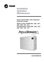
Unit Installation - Indoor Unit<br />
Table 5 - Total unit weight and corner weight (kg)<br />
Shipping Net<br />
Corner Weights<br />
Model Maximum Maximum #1 #2 #3<br />
MCDP 075<br />
MCDP 100<br />
MCDP 125<br />
TTH 150<br />
TTV 150<br />
TTH 175<br />
TTV 175<br />
TTH 200<br />
TTV 200<br />
TTH 240<br />
TTV 240<br />
100<br />
134<br />
140<br />
215<br />
215<br />
215<br />
215<br />
342<br />
342<br />
355<br />
355<br />
82<br />
114<br />
120<br />
190<br />
190<br />
190<br />
190<br />
315<br />
315<br />
315<br />
315<br />
20<br />
28<br />
30<br />
47<br />
44<br />
47<br />
44<br />
79<br />
77<br />
82<br />
82<br />
20<br />
28<br />
30<br />
48<br />
50<br />
48<br />
50<br />
86<br />
79<br />
90<br />
90<br />
21<br />
29<br />
30<br />
48<br />
50<br />
48<br />
50<br />
86<br />
79<br />
90<br />
90<br />
#4<br />
21<br />
29<br />
30<br />
47<br />
46<br />
47<br />
46<br />
77<br />
79<br />
80<br />
80<br />
prevent the straps from crushing the<br />
unit cabinet or damaging the unit finish.<br />
Installation Consideration<br />
For proper installation and operation,<br />
check each of the following before<br />
mounting the units.<br />
a. Space Requirement and<br />
Clearance<br />
Allow adequate space for the unit and<br />
free air or service clearance. See Figure<br />
1a.<br />
lnstallation, Limitation and<br />
Important Recommendation<br />
The general location of the air handler<br />
is normally selected by the architect,<br />
contractor, and/or buyer. For proper<br />
installation, the following items must be<br />
considered.<br />
a. Available power supply must agree<br />
with electrical data on component<br />
nameplate.<br />
b. Air handler shipped wired for 380-415<br />
volt applications.<br />
c. lf external accessories are installed<br />
on the unit, additional clearance must<br />
be provided.<br />
d.All duct work should be properly<br />
insulated to prevent condensation<br />
and heat loss.<br />
e.Refrigerant gas piping must be<br />
insulated.<br />
Caution<br />
Properly insulate all refrigerant gas<br />
piping to prevent possible water<br />
damage due to condensation and to<br />
prevent capacity loss and possible<br />
compressor damage.<br />
- It is recommended that the outline<br />
drawings provided be studied and<br />
dimensions properly noted and<br />
checked against selected installation<br />
site. By noting in advance which<br />
knockouts are to be used, proper<br />
clearance allowances can be made for<br />
installation and possible future<br />
service.<br />
lf adding external accessories to the<br />
unit, additional clearances must be considered<br />
for the overall space needed.<br />
Lifting Recommendation<br />
Before preparing the unit for lifting, the<br />
center of gravity should be determined<br />
for lifting safety. Because of placement<br />
of internal components, the unit weight<br />
may be unevenly distributed.<br />
Approximate total unit weight and<br />
corner weights are given in Table 5.<br />
(and Figure 2a, 2b)<br />
Warning<br />
On site lifting equipment must be<br />
capable of lifting the weight of the unit<br />
with an adequate safety factor. The use<br />
of under-capacity lifting devices may<br />
result in personal injury or death and<br />
cause damage to the unit.<br />
The crated unit can be moved using a<br />
forklift of suitable capacity. For lifting<br />
the unit into an elevated mounting<br />
position, run lifting straps or slings<br />
under the unit and attach securely to<br />
the lifting device. Use spreader bars to<br />
protect the unit casing from damage.<br />
Test lift the unit to determine proper<br />
balance and stability.<br />
Caution<br />
Use spreader bars to prevent straps<br />
from damaging the unit. Install the bars<br />
between lifting straps, both underneath<br />
the unit and above the unit. This will<br />
Figure 1a<br />
Space requirement for TTV Vertical<br />
model.<br />
For servicing and routine<br />
maintenance, provide access to the unit<br />
through removable panels in the ceiling<br />
see Figure 1b.<br />
Figure 1b<br />
Space requirement for TTH Horizontal<br />
mode.<br />
13