IOM Manual
IOM Manual
IOM Manual

Create successful ePaper yourself
Turn your PDF publications into a flip-book with our unique Google optimized e-Paper software.
TRANE<br />
R<br />
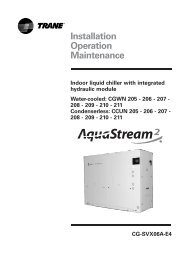
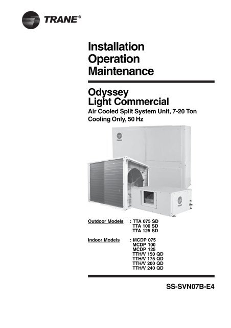
Installation<br />
Operation<br />
Maintenance<br />
Odyssey<br />
Light Commercial<br />
Air Cooled Split System Unit, 7-20 Ton<br />
Cooling Only, 50 Hz<br />
Outdoor Models<br />
: TTA 075 SD<br />
TTA 100 SD<br />
TTA 125 SD<br />
Indoor Models : MCDP 075<br />
MCDP 100<br />
MCDP 125<br />
TTH/V 150 QD<br />
TTH/V 175 QD<br />
TTH/V 200 QD<br />
TTH/V 240 QD<br />
SS-SVN07B-E4
TRANE ®<br />
Important Note: Installation procedures<br />
should be performed in the sequence<br />
that they appear in this manual. This<br />
manual is customer' s property. Do not<br />
destroy or remove the manual from the<br />
unit. The manual should remain weather<br />
protected with the unit until all<br />
installation procedures are completed.<br />
Warning: Open and lock the disconnect<br />
switch before attempting any installation<br />
of maintenance. Failure to do so will<br />
cause severe injury even to death for<br />
electrical shock or contact with moving<br />
parts.<br />
Note: It is not the intention of this<br />
manual to cover all possible variations<br />
in systems that may occur or to provide<br />
comprehensive information concerning<br />
every possible contingency that may be<br />
encountered during an installation. If<br />
additional information is required or if<br />
specific problems arise that are not fully<br />
discussed in this manual, contact your<br />
local Sales office.<br />
Note: Warning and Cautions appear at<br />
appropriate places in this manual. Your<br />
personal safety and the proper<br />
operation of this machine require that<br />
you follow them carefully. The Company<br />
assumes no liability for installation or<br />
servicing performed by unqualified personnel.<br />
i
TRANE ®<br />
Contents<br />
General Information<br />
Outdoor Unit - TTA Model Nomenclature<br />
General Data - Outdoor Unit<br />
Dimensional Data - TTA Only<br />
Unit Installation - Outdoor Unit<br />
Space Clearance Data - Outdoor Unit<br />
Model Number Description<br />
General Data<br />
Dimensional Data<br />
Unit Installation - Indoor Unit<br />
System Refrigerant Piping<br />
System Refrigerant Charging Procedures<br />
Field Wiring Instructions<br />
Schematic Wiring Diagram<br />
Interfacing Wiring Diagram<br />
Wired Control Installation<br />
Wired Control<br />
System Operation<br />
Operation and Start-Up<br />
Maintenance<br />
Trouble Analysis<br />
Trouble Analysis - Discharge Chart<br />
Commissioning Log Sheet<br />
Installation Checklist<br />
1<br />
2<br />
3<br />
4<br />
5<br />
6<br />
7<br />
8-9<br />
10-12<br />
13-16<br />
17-18<br />
19<br />
20<br />
21<br />
22-23<br />
24<br />
25<br />
26<br />
27<br />
28<br />
29-31<br />
32<br />
33<br />
34<br />
ii
TRANE ®<br />
General Information<br />
Foreword<br />
These instructions do not attempt to<br />
cover all variations in systems, nor to<br />
provide for every possible contingency<br />
to be met in connection with installation.<br />
Should further information be desired<br />
or should particular problems arise<br />
which are not sufficiently covered for the<br />
purchaser's purpose, the matter should<br />
be referred to the manufacturer.<br />
Reception<br />
On arrival, inspect the unit before<br />
signing the delivery note. Specify any<br />
damage on the delivery note, and send<br />
a registered letter of protest to the last<br />
carrier of the goods within 72 hours of<br />
delivery. Notify the local Trane Sales<br />
Office at the same time. The unit should<br />
be totally inspected within 15 days of<br />
delivery. lf any concealed damage is<br />
discovered, stop unpacking the<br />
shipment. Take photos of the damage<br />
material if possible. Notify the carrier<br />
immediately by phone and registered<br />
mail. Notify the local Trane Sales Office.<br />
Concealed damage must be reported<br />
within 15 days of delivery. Check the<br />
unit nameplate to confirm that the<br />
proper unit was shipped. Available<br />
power supply must be compatible with<br />
electrical characteristics specified on<br />
component nameplates.<br />
General Information<br />
This manual covers the installation,<br />
operation and maintenance of Trane<br />
Indoor / Outdoor units.<br />
Note<br />
Handling<br />
The unit will be supplied with a shipping<br />
base and protective packaging over the<br />
unit casing. The packaging should be<br />
kept on the unit during handling or<br />
storage on site.<br />
lf it is necessary to remove the<br />
packaging for inspection prior to<br />
completion of on site handling, retain<br />
packaging parts and reapply them by<br />
tapping in position to prevent damage<br />
to the casing. The unit as supplied has<br />
a shipping base which is suitable for<br />
handling by a fork lift truck. lf it is<br />
necessary to sling the unit, use<br />
spreader bars under the shipping base.<br />
Ensure that ropes do not cause<br />
abrasion to the surface of the unit.<br />
Warning<br />
Open and lock unit disconnect to<br />
prevent injury or death from electric<br />
shock or contact with moving parts<br />
before attempting any installation or<br />
maintenance.<br />
lnspection<br />
lnspect material carefully for any<br />
shipping damage. lf damaged, it must<br />
be reported to, and claims made against<br />
the transportation company. Replace<br />
damaged parts with authorized parts<br />
only. Check the unit nameplate to<br />
confirm that the proper unit was<br />
shipped. Available power supply must<br />
be compatible with electrical<br />
characteristics specified on component<br />
nameplates.<br />
"Warnings" and "Cautions" appear at<br />
appropriate places in this manual. Your<br />
personal safety and the proper<br />
operation of this machine require that<br />
you follow them carefully. The<br />
manufacturer assumes no liability for<br />
installations or servicing performed by<br />
unqualified personnel.<br />
1
Outdoor Unit -<br />
TTA Model Nomenclature<br />
T T A 0 7 5 S D 1 X A 0 S A B<br />
1 2 3 4 5 6 7 8 9 10 11 12 13 14 15<br />
Digit 1,2<br />
T<br />
T<br />
TRANE ® 2<br />
Condensing Unit / Cooling only<br />
Digit 3<br />
A<br />
Air Cooled<br />
Digit 4,5,6<br />
Digit 7<br />
Digit 8<br />
Digit 9<br />
Digit 10<br />
Digit 11<br />
Digit 12<br />
Digit 13<br />
Digit 14<br />
0 7 5<br />
S<br />
D<br />
1<br />
X<br />
A<br />
0<br />
S<br />
A<br />
Nominal Cooling Capacity, MBH<br />
075 = 84 MBH<br />
100 = 106 MBH<br />
125 = 127 MBH<br />
Development Sequence<br />
Electrical Rating / Utilization Range<br />
D = 380 - 415V / 3Phase / 50 Hz<br />
Factory Mounted Control<br />
1 = DOL Starter<br />
Factory Installed Option<br />
X = None<br />
F = Corrosion Resistant Fin<br />
G = Coil Guard Assembly<br />
H = F & G<br />
Refrigerant Type<br />
A = R22<br />
B = R407C<br />
Future Use<br />
Operating Ambient<br />
S = Standard Ambient<br />
H = High Ambient Option<br />
Minor Design Sequence<br />
Digit 15<br />
Matching Flexibility<br />
Table - 4<br />
B<br />
OURDOOR UNIT<br />
TTA 075 S<br />
TTA 100 S<br />
TTA 125 S<br />
2 x TTA 075 S<br />
TTA 075 + TTA 100 S<br />
2 x TTA 100 S<br />
2 x TTA 125 S<br />
Service Indicator<br />
INDOOR UNIT<br />
MCDP 075<br />
MCDP 100<br />
MCDP 125<br />
1 x TTH/TTV 150<br />
1 x TTH/V 175<br />
1 x TTH/TTV 200 Q<br />
1 x TTH/TTV 240 Q
TRANE ®<br />
General Data - Outdoor Unit<br />
Table 1<br />
Performances (1)<br />
TTA 075<br />
TTA 100<br />
TTA 125<br />
Unit Capacity Steps (%)<br />
Total Compressor Power Input (1)<br />
Main Power Supply<br />
Utilization Range<br />
Compressor<br />
Number<br />
Type<br />
Unit MCA(2)<br />
RLA / LRA<br />
Motor RPM<br />
Sump Heater (Optional) per compressor<br />
Coil<br />
Type<br />
Tube Size<br />
Tube Type / Material<br />
Height<br />
Length<br />
Quantity [per TTA]<br />
Face Area [per TTA]<br />
Rows<br />
Fins Per Foot (fpf)<br />
Fan<br />
Type<br />
Number<br />
Diameter<br />
Drive Type<br />
Speeds Number<br />
Air Flow<br />
Motors Quantity<br />
Motors kW (2)<br />
FLA/LRA (2)<br />
Motor RPM<br />
Liquid and Suction connection<br />
Suction Connection<br />
Liquid Connection<br />
Unit Dimensions / Weight<br />
Width X Height X Length<br />
Weight Crated<br />
System Data<br />
Refrigerant Circuit [per TTA]<br />
KW<br />
V/Ph/Hz<br />
A<br />
A<br />
rpm<br />
W<br />
mm (in)<br />
mm<br />
mm<br />
m2<br />
mm (in)<br />
cmh (cfm)<br />
kw (hp)<br />
A<br />
rpm<br />
brazed<br />
brazed<br />
mm<br />
kg<br />
0-100<br />
6.9<br />
1<br />
17<br />
16.4/95<br />
2<br />
1.77<br />
1<br />
168<br />
1<br />
16200 (9535)<br />
1<br />
165<br />
1<br />
0-100<br />
9.1<br />
415/3/50<br />
400V +/- 10%<br />
1<br />
Hermetic Scroll<br />
21<br />
19.2/125<br />
2900<br />
90<br />
Plate Fin<br />
9.52 (3/8)<br />
Smooth Bore / Copper<br />
914<br />
965<br />
2<br />
1.77<br />
2<br />
144<br />
Propeller<br />
1<br />
660 (26)<br />
Direct Drive, 3 phase<br />
1<br />
15700 (9240)<br />
1<br />
0.6 (0.75)<br />
1.3 / 5.66<br />
910<br />
1 1/8"<br />
1/2"<br />
1115 x 945 x 935<br />
197<br />
1<br />
0-100<br />
10.2<br />
1<br />
24<br />
22.1/125<br />
2<br />
1.77<br />
2<br />
168<br />
1<br />
15400 (9064)<br />
1<br />
230<br />
1<br />
Refrigerant Charge<br />
Approximate per circuit<br />
kg<br />
5.4<br />
6.3<br />
6.7<br />
Notes<br />
[1] at 7 deg C SST and 35 deg C Ambient, 420V,<br />
[2] Minimum Circuit Ampacity (MCA) is 125% of the largest compressor RLA plus 100% of the other compressor RLA<br />
plus the sum of the condenser fan FLA.<br />
3
TRANE ® 4<br />
Dimensional Data -<br />
Outdoor Unit TTA 075/100/125
TRANE ®<br />
Unit Installation - Outdoor Unit<br />
Installation Clearances<br />
Provide enough space around the unit<br />
to allow unrestricted access to all<br />
service points. Refer to unit space<br />
clearance data for minimum required<br />
service and free air clearances.<br />
Observe the following points to insure<br />
proper unit operation.<br />
Refer to table 2 for reccomended<br />
spacing.<br />
a. Don't install the unit under low shield.<br />
Keep discharge air freely.<br />
Ground Level Mounting<br />
The unit base should be adequately<br />
supported and hold the unit near level.<br />
Any ground level location must comply<br />
with the required clearances. Place the<br />
unit on a 102 mm cement support plate.<br />
The support should extend 51mm<br />
beyond the unit base channel at all<br />
points. The unit and support should be<br />
Isolated from any adjacent structure to<br />
prevent possible noise or vibration<br />
problem.<br />
Important: Don't block discharge air.<br />
This can result in warm air recirculation<br />
through the coil.<br />
b. Don't locate the unit in a position<br />
where runoff water can drop into the fan<br />
discharge openings.<br />
c. Intake air can be supplied from 2<br />
sides of unit.<br />
Rooftop Mounting<br />
If the unit is roof mounted, be sure the<br />
structure is strong enough to support<br />
the overall weight of the unit and all<br />
accessories. Refer to Table 1 for unit<br />
weight details.<br />
Warning: Ensure the structure is strong<br />
enough to support the gross weight of<br />
unit and its accessories. Failure to do<br />
will result in severe injury or death and<br />
can seriously damage the unit and<br />
building.<br />
The unit should be elevated on a<br />
horizontal, field-fabricated 102 mm steel<br />
frame or 100 X 100 mm wooden<br />
mounting frame. Complete the frame<br />
and fix it firmly on the roof. The frame<br />
must support a minimum of three of the<br />
unit' s four sides and can span the roof<br />
supports to distribute the load on the<br />
roof.<br />
5
TRANE ® 6<br />
Space Clearance Data -<br />
Outdoor Unit<br />
TABLE 2 - TTA INSTALLATION CLEARANCE
TRANE ®<br />
Model Number Description<br />
MCDP Model Nomenclature<br />
M C D P 0 7 5 B 1 0 0 0 0 A A<br />
1 2 3 4 5 6 7 8 9 10 11 12 13 14 15<br />
Digit 1,2,3<br />
Digit 4<br />
M C D<br />
P<br />
InDoor Unit, Horizontal Discharge / Cooling Only<br />
Development Sequence<br />
Digit 5,6,7<br />
0 7 5<br />
Nominal Cooling Capacity, MBH<br />
075 = 75 MBH<br />
100 = 100 MBH<br />
125 = 125 MBH<br />
MCDP Models<br />
MCDP 075<br />
MCDP 100 / 125<br />
MTR, Kw<br />
D = 0.75<br />
E = 1.1<br />
Digit 8<br />
B<br />
Electrical Rating / Utilization Range<br />
B = 220 - 240V / 1Ph / 50 Hz<br />
Digit 9<br />
Digit 10<br />
Digit 11<br />
Digit 12<br />
Digit 13<br />
Digit 14<br />
1<br />
0<br />
0<br />
0<br />
0<br />
A<br />
Factory Mounted Control<br />
1 = DOL Starter c/w Temperature Controller<br />
Future Use<br />
Future Use<br />
Future Use<br />
Future Use<br />
Minor Design Sequence<br />
Digit 15<br />
A Service Indicator<br />
TTH Model Nomenclature<br />
1 2 3 4 5 6 7 8 9 10 11 12 13 14 15<br />
T T H 1 2 5 Q D 1 D 0 0 0 B A<br />
Digit 1,2<br />
Digit 3<br />
Digit 4,5,6<br />
Digit 7<br />
Digit 8<br />
Digit 9<br />
T T<br />
H<br />
1 5 0<br />
Q<br />
D<br />
1<br />
InDoor Unit / Cooling Only<br />
Air Flow Configuration<br />
H = Horizontal Discharge<br />
V = Vertical Discharge<br />
Nominal Cooling Capacity, MBH<br />
150 = 150 MBH 200 = 200 MBH<br />
175 = 175 MBH 240 = 240 MBH<br />
Development Sequence<br />
Electrical Rating / Utilization Range<br />
B = 220 - 240V / 1Ph / 50 Hz<br />
Factory Mounted Control<br />
1 = DOL Starter c/w Temperature Controller<br />
Digit 10<br />
Digit 11<br />
Digit 12<br />
Digit 13<br />
G<br />
0<br />
0<br />
0<br />
Installed Motor kW<br />
Future Use<br />
Future Use<br />
Future Use<br />
TTH Models<br />
TTH 150/175<br />
TTH 200<br />
TTH 240<br />
Std. MTR, kW<br />
G = 2.2<br />
H = 3.0<br />
J = 4.0<br />
Oversize MTR; Kw<br />
J = 4.0<br />
K = 5.5<br />
K = 5.5<br />
Digit 14<br />
Digit 15<br />
B<br />
A<br />
Minor Design Sequence<br />
B = Second. (Year 2006, TTH/BDHB Casing Rationalization)<br />
Service Indicator<br />
7
TRANE ® 8<br />
General Data<br />
Odyssey Condensing Units General Data<br />
Performances (1)<br />
TTA 075<br />
TTA 100<br />
TTA 125<br />
2xTTA 075<br />
TTA075+100<br />
2xTTA 100 TTA100+125<br />
2xTTA125<br />
Unit Capacity Steps (%)<br />
Total Compressor Power Input (1)<br />
Main Power Supply<br />
Utilization Range<br />
Compressor<br />
Number<br />
Type<br />
Unit MCA Amps (4)<br />
RLA / LRA (2)<br />
Motor RPM<br />
Sump Heater (Optional) per compressor<br />
Liquid and Suction Connection<br />
Suction Connection<br />
Liquid Connection<br />
Coil<br />
Type<br />
Tube Size<br />
Tube Type<br />
Height<br />
Length<br />
Quantity [per TTA]<br />
Face Area [per TTA]<br />
Rows [std. Ambient]<br />
Fins Per Foot (fpf)<br />
Fan<br />
Type<br />
Number<br />
Diameter<br />
Drive Type<br />
Speeds Number<br />
Air Flow<br />
Motors Quantity<br />
Motors kW (2)<br />
FLA / LRA (2)<br />
Motor RPM<br />
Dimensions<br />
Height<br />
Width<br />
Length<br />
Weight Crated<br />
System Data<br />
Retrigerant Circuit [per TTA]<br />
Refrigerant Charge (3)<br />
Approximate per circuit<br />
TTA only<br />
Notes:<br />
[1] at 7 deg C SSt and 35 deg C Ambient, 420V,<br />
[2] Per Motor @ 400V<br />
[3] Per Circuit<br />
(kW)<br />
(A)<br />
(A)<br />
(rpm)<br />
(W)<br />
brazed<br />
brazed<br />
(mm)<br />
(mm)<br />
(mm)<br />
(m2)<br />
(mm)/(in)<br />
(mm)<br />
(mm)<br />
(mm)<br />
(kg)<br />
(kg)<br />
0-100<br />
6-9<br />
400/3/50<br />
1<br />
21.7<br />
12.4/95<br />
1 1/8”<br />
1/2”<br />
2<br />
1.77<br />
1<br />
168<br />
1<br />
650 26<br />
165<br />
1<br />
7.8<br />
1-100<br />
9.1<br />
400/3/50<br />
1<br />
21<br />
15.9/125<br />
1 1/8”<br />
1/2”<br />
2<br />
1.77<br />
2<br />
144<br />
1<br />
650 26<br />
197<br />
1<br />
8.8<br />
0-100<br />
10.2<br />
400/3/50<br />
1<br />
24<br />
17.9/125<br />
1 1/8”<br />
1/2”<br />
2<br />
1.77<br />
2<br />
168<br />
1<br />
650 26<br />
230<br />
1<br />
9.5<br />
0-50-100<br />
13.8<br />
400/3/50<br />
400V+, -10%<br />
2<br />
2<br />
Hermetic Scroll<br />
1 1/8”<br />
1/2”<br />
2<br />
1.77<br />
1<br />
168<br />
2<br />
650 26<br />
2<br />
650 26<br />
Direct Drive, 3 Phase<br />
1<br />
(m3/h)/(cfm) 15200 9535<br />
1<br />
1<br />
15700 9240<br />
1<br />
1<br />
15400 9064<br />
1<br />
1<br />
32400 19070<br />
2<br />
1<br />
31899 18775<br />
2<br />
kW/hp<br />
0.55/0.75<br />
(A)<br />
1.8/5.66<br />
(rpm)<br />
910<br />
330<br />
1<br />
Plate Fin<br />
9.52<br />
Smooth<br />
914<br />
965<br />
Propeller<br />
945<br />
1115<br />
935<br />
0-50-100<br />
16.0<br />
400/3/50<br />
1 1/8”<br />
1/2”<br />
2<br />
1.77<br />
1 & 2<br />
168 & 144<br />
352<br />
1<br />
0-50-100<br />
19.3<br />
400/3/50<br />
2<br />
1 1/8”<br />
1/2”<br />
2<br />
1.77<br />
2<br />
144<br />
2<br />
650 26<br />
0-50-100<br />
19.3<br />
400/3/50<br />
2<br />
1 1/8”<br />
1/2”<br />
2<br />
1.77<br />
2<br />
144 & 168<br />
2<br />
650 26<br />
1<br />
1<br />
31899 18480 31099 18304<br />
2<br />
2<br />
394<br />
[4] Minimum Circuit Ampacity (MCA) is 125% of the largest compressor RLA.<br />
plus 100% of the other compressor RLA plus the sum of the condenser fan FLA.<br />
[5] Standard Ambient range of up to 45 C, with high ambient range of up to 50deg C with the HA Option.<br />
1<br />
427<br />
1<br />
0-50-100<br />
20.4<br />
400/3/50<br />
2<br />
1 1/8”<br />
1/2”<br />
2<br />
1.77<br />
2<br />
168<br />
2<br />
650 26<br />
1<br />
30800 18128<br />
2<br />
460<br />
1
TRANE ®<br />
General Data<br />
Odyssey Air Handling Units General Date<br />
MCDP075 MCDP100 MCDP125 TTH-V 150<br />
Evaporator Coil<br />
Evaporator Rated Air Flow [MCDs at Med, Speed<br />
@ Available ESP at norminal Airflow<br />
Configuration (1)<br />
Face Area<br />
Tube Material<br />
Tube Type<br />
Tube Size (OD)<br />
Rowas / FPF<br />
No. Of Circuits<br />
Refrigerant Flow Control<br />
Drain Connection Size<br />
Evaporator Fan / Motor<br />
Motor<br />
Utilization Range<br />
FLA (each) (2)<br />
LRA<br />
Diameter of Fan<br />
Width of Fan<br />
No of Fans<br />
Indoor Fan Type<br />
Nominal Fan Speed<br />
Cfm<br />
Cmh<br />
Pg<br />
High Pa [3]<br />
Med. Pa [3]<br />
Low. Pa [3]<br />
sq. ft /m2<br />
in / mm<br />
in<br />
Drive Type<br />
(Hi/Med/Low)(3)<br />
Std. kW<br />
in / mm<br />
in / mm<br />
RPM<br />
2400<br />
4078<br />
163<br />
263<br />
182<br />
51<br />
H<br />
5/0.46<br />
3/144<br />
1<br />
3/4<br />
5.8/5.5/4.4<br />
12.1/8.9/7<br />
0.75<br />
9/229<br />
7/176<br />
2<br />
1250/1300/1350<br />
3225<br />
5479<br />
111<br />
248<br />
238<br />
158<br />
H<br />
6.7/0.62<br />
3/144<br />
1<br />
3/4<br />
9/8,5/7,5<br />
23.8/16.9/13<br />
1.1<br />
9/229<br />
9/229<br />
2<br />
1235/1345/1410<br />
3237<br />
5500<br />
111<br />
248<br />
238<br />
158<br />
H<br />
6.7/0.62<br />
4/144<br />
1<br />
3/4<br />
9/8,5/7,5<br />
23.8/16.9/13<br />
1.1<br />
9/229<br />
9/229<br />
2<br />
1235/1345/1410<br />
4750<br />
8070<br />
125<br />
H and V<br />
10.22/0.95<br />
3/144<br />
2<br />
1.5<br />
4.70<br />
29.40<br />
2.2<br />
15/361<br />
15/361<br />
1<br />
836<br />
Liquid / Suction Line OD<br />
Approx. Operating Weight<br />
Unit Dimensions [uncrated]<br />
in<br />
kg<br />
HxWxD mm<br />
1/2 [1 1/8]<br />
82<br />
398x1217x996<br />
1/2 [1 1/8]<br />
114<br />
398x1593x995<br />
1/2 [1 1/8]<br />
120<br />
396x1593x995<br />
1/2 [1 1/8]<br />
190<br />
1423x1436x702<br />
Notes:<br />
1 H = Horizontal Only. V = Verticle Only. 2 Per Motor @ 400V [std kW] 3 For direct droves only.<br />
TTH-V 175<br />
5300<br />
9005<br />
125<br />
H & V<br />
10.22/0.95<br />
3/144<br />
2<br />
1.5<br />
4.70<br />
29.40<br />
2.2<br />
15/381<br />
15/381<br />
1<br />
843<br />
1/2 [1 1/8]<br />
190<br />
1423x1436x702<br />
TTH-V 200<br />
650<br />
11044<br />
188<br />
H & V<br />
15/1.39<br />
3/144<br />
2<br />
1.5<br />
6.20<br />
40.20<br />
3<br />
16/457<br />
18/457<br />
1<br />
823<br />
1/2 [1 1/8]<br />
315<br />
1673x1628x772<br />
TTH-V 240<br />
8000<br />
13592<br />
188<br />
H & V<br />
15/1.39<br />
3/144<br />
2<br />
1.5<br />
8<br />
38.20<br />
4<br />
18/457<br />
18/457<br />
1<br />
833<br />
1/2 [1 1/8]<br />
315<br />
1673x1628x772<br />
9
TRANE ® 10<br />
Dimensional Data -<br />
MCDP 075-125
TRANE ®<br />
Dimensional Data -<br />
TTH/V 150-175<br />
11
TRANE ®<br />
Dimensional Data -<br />
TTH/V 200-240<br />
12
TRANE ®<br />
Unit Installation - Indoor Unit<br />
Table 5 - Total unit weight and corner weight (kg)<br />
Shipping Net<br />
Corner Weights<br />
Model Maximum Maximum #1 #2 #3<br />
MCDP 075<br />
MCDP 100<br />
MCDP 125<br />
TTH 150<br />
TTV 150<br />
TTH 175<br />
TTV 175<br />
TTH 200<br />
TTV 200<br />
TTH 240<br />
TTV 240<br />
100<br />
134<br />
140<br />
215<br />
215<br />
215<br />
215<br />
342<br />
342<br />
355<br />
355<br />
82<br />
114<br />
120<br />
190<br />
190<br />
190<br />
190<br />
315<br />
315<br />
315<br />
315<br />
20<br />
28<br />
30<br />
47<br />
44<br />
47<br />
44<br />
79<br />
77<br />
82<br />
82<br />
20<br />
28<br />
30<br />
48<br />
50<br />
48<br />
50<br />
86<br />
79<br />
90<br />
90<br />
21<br />
29<br />
30<br />
48<br />
50<br />
48<br />
50<br />
86<br />
79<br />
90<br />
90<br />
#4<br />
21<br />
29<br />
30<br />
47<br />
46<br />
47<br />
46<br />
77<br />
79<br />
80<br />
80<br />
prevent the straps from crushing the<br />
unit cabinet or damaging the unit finish.<br />
Installation Consideration<br />
For proper installation and operation,<br />
check each of the following before<br />
mounting the units.<br />
a. Space Requirement and<br />
Clearance<br />
Allow adequate space for the unit and<br />
free air or service clearance. See Figure<br />
1a.<br />
lnstallation, Limitation and<br />
Important Recommendation<br />
The general location of the air handler<br />
is normally selected by the architect,<br />
contractor, and/or buyer. For proper<br />
installation, the following items must be<br />
considered.<br />
a. Available power supply must agree<br />
with electrical data on component<br />
nameplate.<br />
b. Air handler shipped wired for 380-415<br />
volt applications.<br />
c. lf external accessories are installed<br />
on the unit, additional clearance must<br />
be provided.<br />
d.All duct work should be properly<br />
insulated to prevent condensation<br />
and heat loss.<br />
e.Refrigerant gas piping must be<br />
insulated.<br />
Caution<br />
Properly insulate all refrigerant gas<br />
piping to prevent possible water<br />
damage due to condensation and to<br />
prevent capacity loss and possible<br />
compressor damage.<br />
- It is recommended that the outline<br />
drawings provided be studied and<br />
dimensions properly noted and<br />
checked against selected installation<br />
site. By noting in advance which<br />
knockouts are to be used, proper<br />
clearance allowances can be made for<br />
installation and possible future<br />
service.<br />
lf adding external accessories to the<br />
unit, additional clearances must be considered<br />
for the overall space needed.<br />
Lifting Recommendation<br />
Before preparing the unit for lifting, the<br />
center of gravity should be determined<br />
for lifting safety. Because of placement<br />
of internal components, the unit weight<br />
may be unevenly distributed.<br />
Approximate total unit weight and<br />
corner weights are given in Table 5.<br />
(and Figure 2a, 2b)<br />
Warning<br />
On site lifting equipment must be<br />
capable of lifting the weight of the unit<br />
with an adequate safety factor. The use<br />
of under-capacity lifting devices may<br />
result in personal injury or death and<br />
cause damage to the unit.<br />
The crated unit can be moved using a<br />
forklift of suitable capacity. For lifting<br />
the unit into an elevated mounting<br />
position, run lifting straps or slings<br />
under the unit and attach securely to<br />
the lifting device. Use spreader bars to<br />
protect the unit casing from damage.<br />
Test lift the unit to determine proper<br />
balance and stability.<br />
Caution<br />
Use spreader bars to prevent straps<br />
from damaging the unit. Install the bars<br />
between lifting straps, both underneath<br />
the unit and above the unit. This will<br />
Figure 1a<br />
Space requirement for TTV Vertical<br />
model.<br />
For servicing and routine<br />
maintenance, provide access to the unit<br />
through removable panels in the ceiling<br />
see Figure 1b.<br />
Figure 1b<br />
Space requirement for TTH Horizontal<br />
mode.<br />
13
TRANE ®<br />
Unit Installation - Indoor Unit<br />
b. Location, Mounting and<br />
Positioning<br />
Before installing any unit make sure<br />
proper preparation has been made at<br />
each unit locating for piping and<br />
electrical connections.<br />
Figure 2a<br />
Figure 2b<br />
Horizontal Suspension<br />
lf the air handler will be suspended, use<br />
a suspension mounting kit to isolate the<br />
unit from the structure. This is usually<br />
accomplished through the use of spring<br />
or rubber isolators. Mounting rods must<br />
be field supplied. Isolator selection is<br />
dependent upon total unit weight,<br />
including accessories. Approximate<br />
unit weights are provided in Table 5.<br />
See Figure 2b (for horizontal<br />
configuration) and see Figure 2a (for<br />
vertical configuration).<br />
Caution<br />
Before hanging the unit on suspension<br />
rods, reinforce the cabinet around the<br />
knockouts, using a large washer inside<br />
the cabinet. Washer should be between<br />
the skin of the air handler and the nut<br />
on the suspension rod.<br />
Align holes (knockouts) in the cabinet<br />
with structural supports and secure<br />
suspensions rods to the structure, then<br />
to the air handler cabinet. If knockout<br />
locations do not permit proper<br />
alignment with existing structure, it may<br />
be necessary to field fabricate cross<br />
members on existing structural beams.<br />
Note<br />
When other that bottom return is to be<br />
used, side panel removed for return<br />
duct installation, must be secured over<br />
the bottom opening.<br />
Auxiliary Drain Pan<br />
A field fabricated auxiliary drain pan<br />
should be installed under the unit for<br />
all horizontal applications, and when air<br />
handlers are installed above ceilings or<br />
in other locations where condensate<br />
overflow may cause damage. This drain<br />
pan will eliminate any excess<br />
condensation that may be due to<br />
extreme humidity or an obstructed drain<br />
in the primary drain pan. Drain lines<br />
from this pan must be installed, but<br />
should not be connected to the primary<br />
drain line from the unit, isolate the<br />
auxiliary drain pan from both the air<br />
handler and the structure.<br />
Positioning and Installation<br />
The final position must be dictated by<br />
required service access to unit, weight<br />
distribution over structural supports,<br />
and by the locations of electrical,<br />
refrigerant and condensate drainage<br />
connections. All refrigerant piping<br />
connections are made inside the<br />
cabinet. They may enter the cabinet<br />
through factory provided knockouts.<br />
Note<br />
TTH/V 150~240<br />
The air handler is designed so that<br />
refrigerant piping can only from the<br />
right hand side.<br />
Caution<br />
• Protect adjacent surfaces from heat<br />
damage, when brazing in and around<br />
the air handler.<br />
• These air handlers are shipped with<br />
a holding charge in the coil. Do not<br />
bleed holding charge until refrigerant<br />
lines ready to be connected.<br />
14
TRANE ®<br />
Unit Installation - Indoor Unit<br />
On air handlers that will have refrigerant<br />
lines entering the cabinet from the right<br />
side, the bulb(s) should be attached to<br />
the suction tube(s) inside the cabinet,<br />
in the same manner as above,<br />
approximately 10" from the right end of<br />
the unit.<br />
After attaching to the suction line(s),<br />
either inside or outside of the cabinet,<br />
wrap the cork impregnated insulation<br />
around the bulb(s) and suction tube(s).<br />
Refrigerant piping should then be<br />
insulated.<br />
Important<br />
Ensure that the refrigerant lines passing<br />
through the cabinet are not resting on<br />
sharp sheet metal edges.<br />
Figure 5<br />
Figure 3<br />
Filters<br />
Air handlers are shipped with 1"<br />
washable filters installed. To replace<br />
filters, slide old filters out and replace<br />
with new ones.<br />
Figure 4<br />
Condensate Piping<br />
These air handlers come standard with<br />
pan. Drain connections are provided<br />
on both sides of the air handler, See<br />
Figure 5.<br />
When it has been decided which nipple<br />
is to be used, remove the plug from<br />
that nipple only.<br />
Important<br />
Figure 6<br />
When air handler is installed in the<br />
vertical position and close proximity<br />
trapping of condensate is required, use<br />
of a subbase accessory to raise the air<br />
handler for clearance of the drain trap<br />
is recommended. For a typical drain<br />
trap assembly, see figure 6<br />
15
TRANE ® 16<br />
Unit Installation - Indoor Unit<br />
Duct Connections<br />
The supply and return ducts should be<br />
connected to the unit with flame<br />
retardant duct connectors to reduce<br />
vibration transmission. The return duct<br />
should be sized to the same dimensions<br />
as the return inlet of the unit.<br />
Electrical Connections<br />
Warning<br />
When installing or servicing this<br />
equipment, always exercise basic<br />
safety precautions to avoid the<br />
possibility of electric shock that could<br />
result in severe personal injury or death.<br />
1. All electrical lines, sizing, protection,<br />
and grounding must be in<br />
accordance with local codes.<br />
2. lf conduit is used, isolate whenever<br />
vibration transmission may cause a<br />
noise problem<br />
within the building structure.<br />
3. Ensure all connections are tight and<br />
no wires exposed.<br />
4. All accessories must be installed and<br />
wired according to the instructions<br />
packaged with that accessory.<br />
Thermostat & Control<br />
Connection<br />
- Mount the thermostat in the desired<br />
location.<br />
- Install color coded cables between<br />
outdoor unit, indoor unit and<br />
thermostat.<br />
- Connect control wiring to the terminal<br />
board located on the side of the fan<br />
control box.<br />
Figure 7<br />
Checkout Procedure<br />
Complete the "Installation Checklist"<br />
at the end of this manual once installed<br />
all field wiring connections. All<br />
operational checks (unit running) must<br />
be made after outdoor unit is installed<br />
and system interconnection is<br />
complete.<br />
Installation Checklist<br />
Complete this checklist once the unit is<br />
installed to verify that all recommended<br />
procedures have been accomplished<br />
before the system is started.<br />
Operational checks cannot be<br />
performed until the system<br />
interconnection is complete.<br />
• Verify that the unit electrical power is<br />
disconnected.<br />
• Inspect all field wiring connections.<br />
All connections should be clean and<br />
tight.<br />
• Inspect unit ground connection(s).<br />
Ground must comply with all<br />
applicable codes.<br />
• Inspect unit suspension arrangement<br />
(if used). Unit position must be<br />
secure. Remove any tools or debris<br />
found in or near the unit.<br />
• Inspect duct outlets. Outlets must be<br />
open and unrestricted.<br />
• Inspect unit drain lines. Pipe<br />
connections must be tight and drain<br />
line unrestricted.<br />
• Inspect fan assembly to insure all<br />
moving parts move freely.<br />
• lf unit is horizontally mounted, make<br />
sure secondary drain pan has been<br />
installed.<br />
• Inspect unit for proper filters, securely<br />
installed. All cabinet panels must be<br />
secured.<br />
• Inspect owner/operator on proper<br />
system operating and maintenanced<br />
procedure.
TRANE ®<br />
System Refrigerant Piping<br />
Structural Preparation for<br />
Outdoor Unit<br />
Holes must be made in the structure to<br />
run refrigerant lines. For the majority<br />
of ground-level installations, the holes<br />
can be made in the header that rests<br />
on top of the foundation. Alternatively,<br />
these holes may also be made in the<br />
foundation itself. On roof-mounted<br />
units, refrigerant lines should enter the<br />
building as close to the unit as possible;<br />
preferably within 76 to 102mm of the<br />
refrigerant connection on the unit, plus<br />
a 152 mm (long radius) 90 degree ell<br />
entering the building (See Figure 8).<br />
Table 2 - Recommended Interconnecting Lines - Condensing Units<br />
Model 0-20 21-40 41-60 61-80<br />
Liq. Suct. Liq. Suct. Liq. Suct. Liq. Suct.<br />
TTA075<br />
TTA100<br />
TTA125<br />
1/2<br />
1/2<br />
1/2<br />
1 1/8<br />
1 1/8<br />
1 1/8<br />
1/2<br />
1/2<br />
1/2<br />
Route refrigerant piping for minimum<br />
linear length, minimum number of<br />
bends and fittings (no reducers) and<br />
minimum amount of line exposed to<br />
outdoor ambient.<br />
Length of Interconnecting Line (feet)<br />
1 1/8<br />
1 1/8<br />
1 1/8<br />
1/2<br />
1/2<br />
1/2<br />
1 1/8<br />
1 1/8<br />
1 1/8<br />
1/2<br />
1/2<br />
1/2<br />
1 1/8<br />
1 1/8<br />
1 1/8<br />
c. lnsulate all refrigerant lines and<br />
joints<br />
d. Pitch all horizontal suction lines<br />
down towards the unit to assist<br />
gravity oil drainage back to the<br />
compressor.<br />
Figure 8 Roftop Mounted Unit<br />
Refrigerant Piping<br />
Guidelines<br />
a.Maximum recommended line<br />
lengths: (per circuit)<br />
Maximum linear length 200 Ft.<br />
Maximum suction line lift 60 Ft.<br />
Maximum liquid line lift 60 Ft.<br />
e. Avoid creating large oil traps in<br />
horizontal suction lines as this will<br />
reduce oil circulating in the system<br />
and may eventually lead to failure of<br />
the compressor.<br />
f. A small oil trap at the end of a<br />
horizontal suction line before a long<br />
vertical riser (of more that 4 meters)<br />
has the advantage of assisting the<br />
high velocity gas to carry the oil up<br />
the vertical pipe.<br />
b. Maximum allowable pressure drops<br />
(R-22):<br />
Suction line<br />
6 psi.<br />
Liquid line<br />
35 psi.<br />
(without subcooler)<br />
Route refrigerant piping for<br />
minimum linear length, minimum<br />
number of bends and fittings (no<br />
reducers) and minimym amount of<br />
line exposed to outdoor ambients.<br />
17
TRANE ® 18<br />
System Refrigerant Piping<br />
Refrigerant Piping<br />
Procedures (Outdoor Unit)<br />
Each unit ships with a dry nitrogen. Due<br />
to this, the charge has to be removed<br />
and the entire system evacuated (at the<br />
proper time) to avoid possible<br />
contamination.<br />
1. Remove the compressor service<br />
access panel.<br />
2. Find the liquid and suction line<br />
service valves. Check that the<br />
piping connection stubs on the<br />
valves line up properly with the<br />
holes in the unit cabinet.<br />
3. Puncture the seal cap on the service<br />
connection stubs to release<br />
remaining refrigerant and nitrogen<br />
(See Figure 9)<br />
5. Cut, fit and braze tubing, starting at<br />
the outdoor unit and work toward the<br />
indoor unit.<br />
Note: Use long radius ells for all 90-<br />
degree bends. All brazing should be<br />
done using 14 to 56kPa dry nitrogen<br />
purge flowing through the pipe being<br />
brazed (See Figure 10).<br />
Caution: Wet-wrap all valves and<br />
protect painted surfaces from excessive<br />
heat. Heat can damage system<br />
components and the units finish.<br />
Note: Install a pressure-regulating valve<br />
between the nitrogen source and the<br />
gauge manifold (See Figure 10).<br />
Unregulated pressure will damage the<br />
unit components.<br />
Leakage Test<br />
Figure 9<br />
Warning: Do not heat the seal caps<br />
unless they have been punctured. If<br />
caps are intact, application of heat may<br />
generate excessive pressure in the<br />
connection stub, causing personal<br />
injury or death due to rupturing of<br />
components and damage to the service<br />
valve.<br />
After the brazing operation of refrigerant<br />
lines to both the outdoor and indoor unit<br />
is completed, the field-brazed<br />
connections must be checked for leaks.<br />
Pressurize the system through the<br />
service valve with dry nitrogen to<br />
1.4MPa. Use soap bubbles or other<br />
leak-checking methods to ensure that<br />
all field joints are leak free. If not,<br />
release pressure, repair and repeat leak<br />
test (See Figure 10).<br />
4. Heat and remove the seal cap and<br />
open the service valve slowly to<br />
release the Nitrogen from the unit.<br />
Caution: Do not remove the seal caps<br />
from refrigerant connections before unit<br />
prepared to braze refrigerant lines to the<br />
connections. Excessive exposure to<br />
atmosphere may allow moisture or dirt<br />
to contaminate the system, damaging<br />
valve seats and causing ice format ion<br />
in system components.<br />
Figure 10
TRANE ®<br />
System Refrigerant<br />
Charging Procedures<br />
Unit Evacuation<br />
1. Evacuate the unit after leakage test.<br />
2. Attach appropriate hoses from<br />
manifold gauge to suction and liquid line<br />
charging port (See Figure 11).<br />
Refrigerant Line Insulation<br />
and Isolation<br />
Insulate the suction line and refrigerant<br />
tubes together, and also insulate liquid<br />
lines exposed on extreme temperatura.<br />
Insulate liquid and suction line<br />
separately and isolate them from each<br />
other. Isolate all refrigerant tubes from<br />
the structures and air ducts.<br />
Note: Isolate the refrigerant tubes from<br />
the building to avoid possible noise and<br />
vibration.<br />
Figure 11<br />
Note: Unnecessary switching of hoses<br />
can be avoided and complete<br />
evacuation of all lines leading to sealed<br />
system can be accomplished with<br />
manifold center hose and connecting<br />
branch hose to a cylinder of refrigerant<br />
and vacuum pump.<br />
Figure 12<br />
3. Connect the center hose of manifold<br />
gauge to a vacuum pump.<br />
4. Evacuate the unit to hold a 46Pa<br />
vacuum.<br />
5. Close the valve to the vacuum pump<br />
and observe the gauge. If gauge<br />
pressure rises above 66Pa within a<br />
minute, it indicates that the vacuum<br />
is not completed or the system has a<br />
leak.<br />
6. If the gauge pressure does not rise<br />
above 66Pa within a minute, it<br />
indicates that the vacuum is<br />
completed.<br />
19
TRANE ® 20<br />
Field Wiring Instructions<br />
Table 6 - Electrical Data - Outdoor Unit<br />
Model<br />
Power supply<br />
Compr. 1<br />
RLA LRA Qty.<br />
Fan Motor @ 415V<br />
KW FLA Qty.<br />
UNIT<br />
MCA<br />
Max Fuse Size &<br />
MCB<br />
TTA 075<br />
TTA 100<br />
TTA 125<br />
360-440 V / 3Ph/50Hz<br />
360-440 V / 3Ph/50Hz<br />
360-440 V / 3Ph/50Hz<br />
12.4<br />
15.9<br />
17.9<br />
95<br />
125<br />
125<br />
1<br />
1<br />
1<br />
0.6<br />
0.6<br />
0.6<br />
1.3<br />
1.3<br />
1.3<br />
1<br />
1<br />
1<br />
16.8<br />
21.2<br />
23.7<br />
29<br />
37<br />
42<br />
Power Supply of the Indoor<br />
/ Outdoor Unit<br />
The installer must provide line voltage<br />
circuit (s) to the unit main power<br />
terminals as shown by the unit wiring<br />
diagrams in wiring. Power supply must<br />
include a disconnect switch in a location<br />
convenient th the unit. Ground the unit<br />
according to local codes and provide<br />
flexible conduit if codes require and/or<br />
if vibration transmission may cause<br />
noise problems.<br />
Important: All the wiring should be in<br />
accordance with local and national<br />
codes. Type and location of disconnect<br />
switch should conform to all general<br />
codes.<br />
Refer to the unit nameplate to detemine<br />
proper wire sizes and protective fusing<br />
requirements. Field wiring diagram for<br />
accessories are shipped in the<br />
accessory.<br />
Low Voltage<br />
Interconnecting Wiring<br />
Install indoor thermostat according to<br />
thermostat installation instructions.<br />
Colorful and rainproof multi-core cable<br />
installation should refer to internal<br />
wiring diagram in this manual. For field<br />
installation, refer to the related section<br />
in this manual for detailed wiring<br />
requirements to connect thermostat to<br />
indoor and outdoor units and wire<br />
routing.<br />
Caution: Use copper conductor only.<br />
Aluminum conductor can not match the<br />
unit terminals. Use of improper wiring<br />
material will damage the equipment.<br />
Warning: Open electrical disconnect<br />
switch and lock it close position to<br />
prevent accidental power application.<br />
Failure to do so may result in serious<br />
personal injury or death due to electrical<br />
shock.
TRANE ®<br />
Schematic Wiring Diagram<br />
Dol Starter With Crankcase<br />
Heater Sales Option 240Vac Control<br />
21
TRANE ® 22<br />
Interfacing Wiring Diagram<br />
1 Fan Speed + 1 or 2 Cool
TRANE ®<br />
Interfacing Wiring Diagram<br />
3 Fan Speed + 1 Cool<br />
23
TRANE ® 24<br />
Wired Control Installation<br />
Locate and attach the<br />
wired control as follows:<br />
1. Do not place the control near heat<br />
sources or expose to the direct rays<br />
of the sun.<br />
2. Do not expose the control to the<br />
indoor unit's supply air stream.<br />
3. Do not place in a confined space.<br />
4. Attach the remote control holder as<br />
shown in Figure 13.<br />
Dimension<br />
Figure 13<br />
Remote Control<br />
Mounting Bracket
TRANE ®<br />
Wired Control<br />
1. Fan<br />
Fan button is not applicable on this<br />
dual stage controller model. The fan<br />
is powered by a single speed motor.<br />
2. Power On/Off<br />
Press POWER button will turn on/ off<br />
the air conditioner. When turned on,<br />
it will operate according to the last program<br />
setting.<br />
3. Temperature Setting<br />
The temperature can be set the range<br />
of 15 O C - 30 O C.<br />
4. Sleep<br />
The facility to raise up the setting<br />
temperature 1 O C (in Cool mode for<br />
the purpose of comfort and energy<br />
saving.<br />
5. Operating Mode<br />
Press MODE button to select system<br />
operating modes. The air conditioner<br />
can be put in 2 modes Only. (COOL<br />
and FAN ).<br />
6. Compressor Status<br />
Dot LED after second digit of 7 -<br />
segment LED, if lit indicates the<br />
compressor is on.<br />
7. Timer<br />
The facility to turn on/off the air<br />
conditioner is 15 hours in advance<br />
TIMER OFF To set timer off by<br />
pressing TIMER button during air<br />
conditioning is on, TIME LED will blink<br />
and will show last hour time setting in<br />
blinking light. Pressing HOUR or<br />
HOUR to increase or decrease hour<br />
digit (between 1 to 15 can be set).<br />
TIMER ON Using same procedure to<br />
set timer off except press TIMER<br />
button during air conditioner is off.<br />
25
TRANE ® 26<br />
System Operation<br />
Notes:<br />
·If TIMER LED is off, HOUR and<br />
HOUR button do not function.<br />
·If TIMER LED is on, pressing<br />
HOUR and HOUR button will<br />
change display time setting to show<br />
hour set left with blinking light. If press<br />
HOUR and HOUR button will<br />
change display to new time setting.<br />
·If the air conditioner stops by power<br />
failure, setting of timer on/off will be<br />
cancelled.<br />
·If POWER button is pressed during<br />
setting if timer, setting of timer on/off<br />
will be cancelled and remote will turn<br />
on/off air conditioner as normal.<br />
·If POWER button is pressed again<br />
during setting time will be cancelled.<br />
Display Unit<br />
The following LEDs are used to<br />
indicates the status,<br />
A LED (in Fan Button) shows when the<br />
fan speed is put in AUTO mode, SLEEP<br />
LED shows the system is put in sleep<br />
mode,<br />
TIMER LED shows when set the timer<br />
on/off. FAN/COOL/LED shows the<br />
operating mode of the air conditioner.<br />
Temperature Display (7-segment LED,<br />
2 digits) show<br />
- The room temperature.<br />
- The setting temperature while blinking.<br />
- "rE", show the room sensor is open or<br />
short circuit.<br />
- "FE" show the freeze sensor is open<br />
or short circuit.<br />
- "Fr" show the evaporator coil is freeze.<br />
System Features<br />
1. Watchdog<br />
There is a circuit in the system to<br />
watch the operation of the<br />
microprocessor.<br />
2. Compressor Delay Proctection<br />
There is a time delay for the<br />
compressor starts to restart.<br />
3. Compressor Minimum on Time<br />
Once the compressor starts to<br />
operate, it will not stop unless the<br />
compressor on time is at least 24<br />
seconds.<br />
4. Non-Volatile Memory<br />
(Auto Restart)<br />
After power interruption, the control<br />
will resume its operation with same<br />
setting parameters except those<br />
related to the time.<br />
5. Freeze Function (Optional)<br />
The facility to stop the compressor if<br />
the indoor coil temperature is below<br />
0 o C.<br />
Operating Precautions<br />
This system must be installed properly<br />
by a qualified installer in accordance with<br />
installation instructions.<br />
Anti-Recycle Timer<br />
- The control system has a build-in 3<br />
minute anti-recycle timer which helps<br />
to preserve the life of system<br />
components.<br />
- Anti-Recycle Timer occur during<br />
operation of unit:<br />
· Temperature setting is adjusted<br />
back and forth.<br />
· ON/OFF switch is turned ON and<br />
OFF.<br />
· Room temperature reaches the<br />
set point.<br />
· Power failure.<br />
Once any of the above conditions<br />
occurs, the anti-recycle timer will start<br />
preventing the operation of the outdoor<br />
unit for approximately 3 minutes.<br />
Freeze Protection<br />
The system is protected against low<br />
indoor coil temperatures. Under certain<br />
conditions, the "COOL/DRY" LED will<br />
blink indicating the proctive function has<br />
been activated. There is no need to<br />
adjust the system.<br />
Stop the air conditioner at<br />
once if any the following<br />
occurs:<br />
- The power cord is too hot to be<br />
touched by hand.<br />
- The insulation of the power cord is<br />
exposed at any point.<br />
- The fuse is blown or circuit breaker<br />
trips frequently.<br />
- The functions of the switches are<br />
inaccurate.<br />
Operating air conditioner<br />
safety.<br />
- Do not insert a bar or similar object<br />
into the supply air outlet.<br />
- Do not pour water directly on the air<br />
conditioner to clean it. If the air<br />
conditioner is operating as wet,<br />
grounding may occur, damaging the<br />
unit.<br />
- Adjust the air flow so it does not blow<br />
directly on room occupants.<br />
- Do not use flammable sprays near the<br />
air conditioner because of danger of<br />
fire.<br />
- Do not use a steel or copper wire in<br />
place of fuses.
TRANE ®<br />
Operation and Start-up<br />
Preparation<br />
Perform the following checks and<br />
inspections before operating the unit:<br />
Inspection Checklist<br />
Unit is mounted securely to the ceiling<br />
support rods (mounting units).<br />
Ductwork connections are complete.<br />
Coil connections are complete and<br />
tight.<br />
Condensate drain pan connections<br />
are complete and tight.<br />
Electrical connections are completed.<br />
Wiring is correct and in accordance<br />
with the wiring diagram.<br />
Ground connection is completed.<br />
Check and retighten if necessary set<br />
screws on the drive, fan pulley, fan<br />
bearings and wheel.<br />
Rotate fan by hand, to ensure that it<br />
runs freely and that there is no<br />
interference.<br />
Check that fan is centrally located in<br />
the housing, axially and radially.<br />
Check and retighten, if necessary,<br />
drive and bearing bolts, motor clamp<br />
plate bolts and isolator bolts.<br />
Check to ensure that pulley are<br />
correctly aligned and that shafts are<br />
parallel.<br />
Check belt tension as per instruction<br />
given in the maintenance section.<br />
If it does not, the power supply should<br />
be switched off at once and all<br />
connections, as well as the power<br />
supply, be re-checked before restarting.<br />
d. In the event of excessive vibrations<br />
or unusual noises, the motor should<br />
be disconnected from the load and<br />
checked for poor alignment, loose<br />
mounting bolts, etc.<br />
e. When the motor has been operated<br />
under load for a short period of time,<br />
check that the operating current totally<br />
with the nameplate current.<br />
Start-Up Procedures<br />
After completing all times under "Pre-<br />
Start-Up", the unit may be started and<br />
the following checks and adjustments<br />
performed.<br />
a. Measure the motor voltage and amps<br />
on all phases to insure proper<br />
operation. Compare these readings<br />
with the motor nameplate.<br />
b. Disconnect load and start motor to<br />
check the direction of rotation. If the<br />
rotation need to be changed, stop the<br />
motor completely and change the<br />
direction of rotation.<br />
c. After connecting the load, the motor<br />
should start quickly and run smoothly.<br />
27
TRANE ® 28<br />
Maintenance<br />
Warning<br />
Disconnect electrical power source and<br />
secure in disconnected position before<br />
servicing the unit. Failure to do so may<br />
result in personal injury or death from<br />
electrical shock.<br />
Monthly Inspection<br />
1. Check condition of air filters and<br />
replace them if necessary.<br />
2. Check the drain pan to be sure that it<br />
is clean and free to carry the flow of<br />
condensate through the drain line.<br />
3. Check the coil surface for cleanliness.<br />
Clean if necessary.<br />
Yearly Inspection<br />
1. Replace filters.<br />
2.Check coil surface. Clean by<br />
vacuuming or flushing with cold<br />
water. Do not use steam or hot water.<br />
3. Carry out checks as detailed in<br />
inspection checklist in the Operation<br />
Section.<br />
4. Inspect the condition of the<br />
evaporator fan belt and replace if<br />
necessary. The belts fitted to TWE<br />
units cannot achieve design<br />
performance without the correct<br />
tensioning.<br />
5. Check condition of vibration isolators,<br />
replace if there is any sign of wear,<br />
loosening or material deterioration.<br />
6.Check fan bearings for noisy<br />
operation and excessive lubricant<br />
leakage. Replace if necessary.<br />
7. Inspect the condensate drain pan and<br />
condensate piping to make sure they<br />
are clear and will carry away all<br />
water.<br />
8. Inspect the control panel wiring to<br />
make sure connections are tight and<br />
insulation is intacted.<br />
Change/ Clean Filters<br />
Change or clean air filters at least twice<br />
a year. Filters will be required more<br />
frequent care under high load condition<br />
or dirty air. A clogged air filters reduces<br />
airflow, cooling capacity and increases<br />
energy usage.<br />
To clean permanent filters, the filter<br />
media and wash it in water to remove<br />
dust, dirt and lint, allow to dry thoroughly<br />
before re-installing in the units.<br />
Do not rub or wring.<br />
Permanent filters can also be cleaned<br />
by blowing with compressed air in<br />
opposite direction of filter airflow.<br />
Belt Maintenance<br />
Clean fan belts and pulleys with a dry<br />
cloth. Oil and grease must be kept off<br />
belts. The use of a belt dressing is not<br />
recommended. When replacing belts,<br />
use a matched set.<br />
Do not force belts onto pulleys, but<br />
adjust motor position to allow mounting<br />
and then re-tighten.<br />
Figure 14<br />
To measure belt tension, use a belt<br />
tensioner as shown in Figure 14.<br />
Determine actual deflection by<br />
depressing one belt tensioner and then<br />
adjust the belt tension to the correct<br />
pounds force and tighten all setscrews<br />
to the proper torques.
TRANE ®<br />
Trouble Analysis<br />
A. Compressor fails to starts<br />
Problems and symptoms<br />
Full voltage at motor terminal but motor<br />
will not run.<br />
Inoperative motor starter.<br />
Open contacts of safety control of<br />
thermal overload.<br />
Electric circuit test shows no current<br />
on line side of motor starter.<br />
Electric circuit test show current on line<br />
but not on motor side or fuse.<br />
Voltmeter does not read proper voltage.<br />
Motor starter holding coil is not<br />
energized.<br />
Probable cause<br />
Burned-out motor.<br />
Burned-out holding coil or broken<br />
contacts.<br />
Safety control of thermal overload<br />
relays has cut outs.<br />
a) Power failure.<br />
b) Disconnect switch open.<br />
Fuse down. Replace fuse<br />
Low voltage<br />
Open control circuit.<br />
Compresoor will not operate.<br />
Open contact on high pressure switch.<br />
Discharge pressure above cut-in<br />
setting.<br />
Frozen compressor due to locked or<br />
damaged mechanism<br />
Discharge pressure above cut-in<br />
setting of high pressure cut-out switch<br />
B. Compressor stops<br />
Problems and symptoms<br />
High pressure control has cut out.<br />
Thermal overload relay has cut out.<br />
Winding thermostat has cut out.<br />
Probable Cause<br />
See H.<br />
a) voltage too low<br />
b)cooling load or condensing<br />
temperature too high<br />
Refrigerant shortage<br />
29
TRANE ®<br />
Trouble Analysis<br />
C. Compressor shortcycles<br />
Problems and symptoms<br />
Suction pressure too low and frosting<br />
at driver.<br />
Motor starts and stops frequently<br />
Probable cause<br />
Restricted liquid liner driver.<br />
Faulty motor.<br />
Recommended action<br />
Replace driver core.<br />
Replace compressor.<br />
D. Compressor runs Continuously<br />
Problems and symptoms<br />
High temperature in conditioned space.<br />
Bubbles in sight glass<br />
E. Compressor loses oil<br />
Problems and symptoms<br />
Oil level too low (sight glass).<br />
Gradual drop of oil level.<br />
Excessively cold suction.<br />
Noisy compressor<br />
F. Compressor is noisy<br />
Problems and symptoms<br />
Abnormally cold suction line:<br />
compressor knocks. Valve bulb<br />
attachment.<br />
Compressor noisy<br />
G. System short of capacity<br />
Problems and symptoms.<br />
Expansion valve hissed.<br />
High pressure drop across filter-drier.<br />
Superheat too high.<br />
Superheat too high.<br />
Probable cause<br />
Excessively high cooling load<br />
a) Lack of refrigerant.<br />
b) Filter driver obstructed<br />
Probable cause<br />
Insufficient oil charge.<br />
Clogged filter drier<br />
Liquid flooding back to compressor<br />
Probable cause<br />
a) Liquid flood-back<br />
b)Expansion Valve stuck in open<br />
position.<br />
Incorrect direction of rotation<br />
Probable cause.<br />
Lack of refrigerant.<br />
Clogged filter-driver.<br />
Superheat set too high.<br />
Excessive pressure drop in the<br />
thermal expansion valve.<br />
Recommended action<br />
Check infiltration and insulation of<br />
conditioned space.<br />
a) Repair leak, add refrigerant.<br />
b) Replace driver core.<br />
Recommended action<br />
All oil.<br />
Replace.<br />
Readjust superheat setting and verify<br />
correct bulb mounting.<br />
Recommended action<br />
a) Check superheat and expansion.<br />
b) Repair or replace<br />
Inverse the direction of rotation<br />
Recommended action<br />
Add refrigerant.<br />
Clean or replace.<br />
Check superheat and adjust<br />
expansion valve<br />
Check superheat and reset thermal<br />
expansion valve<br />
30
TRANE ®<br />
Trouble Analysis<br />
H. Discharge pressure too high<br />
Problems and symptoms<br />
Too little or too warm condenser air.<br />
Restricted air flow.<br />
Excessive discharge pressure.<br />
Probable cause<br />
Excessively warm air leaving<br />
condenser.<br />
Cuts out on high pressure control.<br />
Air or noncondensible gas in system.<br />
Recommended action<br />
Clean coil, check fan and motor for<br />
proper operation.<br />
Remove air or non condensibles.<br />
J. Discharge pressure too high<br />
Problems and symptoms<br />
Bubbles in sight glass.<br />
Probable cause<br />
Lack of refrigerant.<br />
Recommended action<br />
Repair leak and charge.<br />
K. Discharge pressure too high<br />
Problems and symptoms<br />
Compressors run continuously.<br />
Abnormally cold suction line; liquid<br />
flood-back to compressor.<br />
Probable cause<br />
Excessive load on evaporator<br />
a) Expansion valve opens too far.<br />
b) Expansion valve stuck in open<br />
position.<br />
Recommended action<br />
Check system.<br />
a) Adjust superheat and check bulb<br />
attachment.<br />
b) Repair or replace.<br />
L. Discharge pressure too high<br />
Problems and symptoms<br />
Bubbles in sight glass.<br />
High pressure drop across filter-driver.<br />
No refrigerant flow through expansion<br />
valve.<br />
Loss of capacity.<br />
Superheat too high.<br />
This is by no means a complete<br />
analysis of the scroll refrigeration<br />
system. Instead, its intention is to<br />
Probable cause<br />
Lack of refrigerant.<br />
Clogged filter drier.<br />
Expansion valve power element has<br />
lost charge.<br />
Obstructed expansion valve.<br />
Too much pressure drop in evaporator.<br />
familiarize the operator with the<br />
operation of the scroll unit and provide<br />
the background necessary for him to<br />
Recommended action<br />
Repair leak, add refrigerant.<br />
Replace.<br />
Replace valve power element.<br />
Clean or replace.<br />
Check external equaliser of expansion<br />
valve.<br />
recognize and accurately correct or<br />
report any developing problem.<br />
31
Trouble Analysis -<br />
Discharge Chart<br />
System<br />
Faults<br />
Power Supply<br />
High Voltage Wiring<br />
Low Voltage Wiring<br />
Control Transformer<br />
Thermostat<br />
Low Voltage Fuse<br />
Curcuit Breaker<br />
Relay (Fan)<br />
Capacitor (Fan)<br />
Thermal Cutout<br />
Low Indoor Airflow<br />
High Indoor Airflow<br />
Refrig. Undercharge<br />
Refrig. Overcharge<br />
Excessive Evap. Load<br />
Check Valve (Leaking)<br />
Restriction LD Coll<br />
Restriction(TXV or CAP)<br />
Refrigerant Circuit<br />
TRANE ® 32<br />
Head Pressure Too High<br />
Head Pressure Too Low<br />
Suction Pressure Too High<br />
Suction Pressure Too Low<br />
Indoor Coil Frosting<br />
Liquid Floodback (TXV)<br />
Liquid Floodback (Cap.Tube)<br />
Electrical<br />
P<br />
P<br />
P<br />
P<br />
P<br />
P<br />
P<br />
P<br />
P<br />
P<br />
P<br />
P<br />
P<br />
P<br />
P<br />
P<br />
P<br />
I.D. Motor Won' t Start<br />
P<br />
P<br />
P<br />
P<br />
P<br />
P<br />
P<br />
P<br />
P<br />
P Primary Causes - S Secondary Causes
TRANE ®<br />
Commissioning Log Sheet<br />
START-UP ENGINEER/TECHNICIAN NAME : _____________________________________________________<br />
PROJECT NAME<br />
:_____________________________________________________<br />
DEALER/CONTRACTOR<br />
:_____________________________________________________<br />
SALES OFFICE LOCATION<br />
:_____________________________________________________<br />
DATE COMMISSIONED<br />
:_____________________________________________________<br />
1. Nameplate information<br />
Model No: _____________________ Serial No. _____________________________________________________<br />
Voltage: _____________________ RLA: _____________________________________________________<br />
2. Compressor ( S)<br />
A. Voltage at Compressor Terminals<br />
Comp. No. 1: T1 ________________ T2 ________________ T3 ________________<br />
Comp. No. 2: T1 ________________ T2 ________________ T3 ________________<br />
Comp. No. 3: T1 ________________ T2 ________________ T3 ________________<br />
Comp. No. 4: T1 ________________ T2 ________________ T3 ________________<br />
Voltage lmbalance: Comp. "1" ____________ Comp. "2" ____________<br />
Comp. "3" ____________<br />
Comp. "4" ____________<br />
B. Amp Draw<br />
Comp. No. 1: T1 ________________ T2 ________________ T3 ________________<br />
Comp. No. 2: T1 ________________ T2 ________________ T3 ________________<br />
Comp. No. 3: T1 ________________ T2 ________________ T3 ________________<br />
Comp. No. 4: T1 ________________ T2 ________________ T3 ________________<br />
3. Operating Conditions<br />
A. Circuit "A"<br />
Discharge Pressure. ___________________________ Suction Pressure. __________________________<br />
Liquid Line Pressure. ___________________________ Suction Line Temp. __________________________<br />
Liquid Line Temp. ___________________________ SuperHeat. __________________________<br />
Subcooling.<br />
___________________________ Evap. Entering Air Temp. (DB/WB) _______________<br />
Amblent Temp. ___________________________ Evap. Discharge Air Temp. (DB/WB) _______________<br />
B. Circuit "B"<br />
Discharge Pressure. ___________________________ Suction Pressure. __________________________<br />
Liquid Line Pressure. ___________________________ Suction Line Temp. __________________________<br />
Liquid Line Temp. ___________________________ SuperHeat. __________________________<br />
Subcooling.<br />
___________________________ Evap. Entering Air Temp. (DB/WB) _______________<br />
Amblent Temp. ___________________________ Evap. Discharge Air Temp. (DB/WB) _______________<br />
4. Controls<br />
A. All Fans Operating [ ] Yes ___________<br />
Properly? [ ] No ___________ Fan lnoperative<br />
5. Refrigerant Piping<br />
Evacuation Level ___________________ System Charge ___________________<br />
33
TRANE ® 34<br />
Installation Checklist<br />
Trane Air Cooled Condensing Unit<br />
This list must checked off by the installer to ensure correct installation before the unit start up.<br />
Unit acceptance<br />
Check for damage, if any, on transportation<br />
Check for equipment shipped against delivery slip<br />
Check lifting system<br />
Unit positioning<br />
Remove packaging<br />
Check position of unit<br />
Check unit is level<br />
Check clearance around condenser<br />
Check clearance required for maintenance access<br />
Check position of rubber pads<br />
Refrigerant circuit<br />
Check filter dryer and sight glass presence<br />
Check oil traps presence on discharge line ( if there vertical risers>3m)<br />
Check pitch for horizontal lines ( 1 cm/m)<br />
Check refrigerant presence<br />
Electrical equipment<br />
Check direction of rotation of compressors and fan motors<br />
Check installation and rating of mains power switch/fuse<br />
Check that electrical connections comply with specification<br />
Check that electrical connections match information on manufacturer' s identification plate<br />
Check electrical connections and connections to mains power switch<br />
General<br />
Check available cooling charge (50% of rated installation load)<br />
Check with other handling installation works<br />
Comments:........................................................................................................................................................................................................<br />
..............................................................................................................................................................................................................................<br />
...............................................................................................................................................................................................................................<br />
..............................................................................................................................................................................................................................<br />
Signature:........................................................... Name: .................................................................................................................................<br />
Order No: ...........................................................................................................................................................................................................<br />
Work site: ............................................................................................................................................................................................................<br />
Please return to your Trane Service Agency
TRANE ®<br />
Trane<br />
A business of American Standard Companies<br />
www.trane.com<br />
For more information, contact your local district<br />
office<br />
Literature Order Number SS-SVN07B-E4 (November 2006)<br />
File Number<br />
Supersedes<br />
SS-SVN07B-E4 (April 2005)<br />
Stocking Location Malaysia<br />
Trane has a policy of continuous product and product data improvement and reserves the right to charge<br />
design and specifications without notice. Only qualified technicians should perform the installation and<br />
servicing of equipment referred to in this publication.