Emotron FDU 2.0 Variable Speed Drive
Emotron FDU 2.0 Variable Speed Drive Emotron FDU 2.0 Variable Speed Drive
. Torque [%] [4161] MaxAlarmMar (15%) [4171] MaxPreAlMar (10%) [41B] 100% Default: T NOM or Autoset: T MOMENTARY [4181] MinPreAlMar (10%) [4191] MinAlarmMar (15%) Max Alarm Max PreAlarm Min Alarm Min PreAlarm Ramp-up phase [413] Ramp Alarm=On [411] Alarm Select=Max or Max0Min [4162] MaxAlarmDel (0.1s) [4172] MaxPreAlDel (0.1s) [414] Start Delay (0.2s) Stationary phase Stationary phase Ramp-down phase [413] Ramp Alarm=On or Off [413] Ramp Alarm=On or Off [413] Ramp Alarm=On [411] Alarm Select=Max or Max0Min [411] Alarm Select=Max or Max0Min [411] Alarm Select=Max or Max0Min [4162] MaxAlarmDel (0.1s) t [s] [4172] MaxPreAlDel (0.1s) Must be
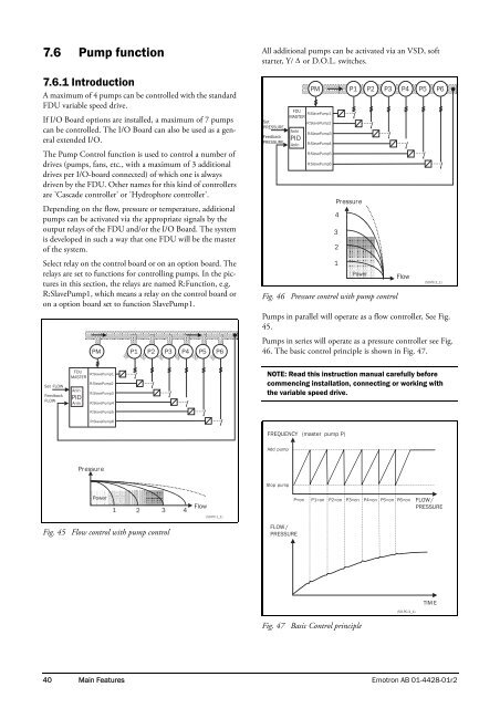
7.6 Pump function 7.6.1 Introduction A maximum of 4 pumps can be controlled with the standard FDU variable speed drive. If I/O Board options are installed, a maximum of 7 pumps can be controlled. The I/O Board can also be used as a general extended I/O. The Pump Control function is used to control a number of drives (pumps, fans, etc., with a maximum of 3 additional drives per I/O-board connected) of which one is always driven by the FDU. Other names for this kind of controllers are 'Cascade controller' or 'Hydrophore controller'. Depending on the flow, pressure or temperature, additional pumps can be activated via the appropriate signals by the output relays of the FDU and/or the I/O Board. The system is developed in such a way that one FDU will be the master of the system. Select relay on the control board or on an option board. The relays are set to functions for controlling pumps. In the pictures in this section, the relays are named R:Function, e.g. R:SlavePump1, which means a relay on the control board or on a option board set to function SlavePump1. PM P1 P2 P3 P4 P5 P6 All additional pumps can be activated via an VSD, soft starter, Y/ Δ or D.O.L. switches. Set PRESSURE Feedback PRESSURE FDU R:SlavePump1 MASTER R:SlavePump2 AnIn PID AnIn PM R:SlavePump3 R:SlavePump4 R:SlavePump5 R:SlavePump6 Pressure Fig. 46 Pressure control with pump control 4 3 2 1 P1 P2 P3 P4 P5 P6 Power Flow (50-PC-2_1) Pumps in parallel will operate as a flow controller, See Fig. 45. Pumps in series will operate as a pressure controller see Fig. 46. The basic control principle is shown in Fig. 47. Set FLOW Feedback FLOW FDU R:SlavePump1 MASTER R:SlavePump2 AnIn PID AnIn R:SlavePump3 R:SlavePump4 R:SlavePump5 R:SlavePump6 NOTE: Read this instruction manual carefully before commencing installation, connecting or working with the variable speed drive. FREQUENCY (master pump P) Add pump Pressure Stop pump Power 1 2 3 4 Flow (50-PC-1_1) P=on P1=on P2=on P3=on P4=on P5=on P6=on FLOW / PRESSURE Fig. 45 Flow control with pump control FLOW / PRESSURE TIM E (50-PC-3_1) Fig. 47 Basic Control principle 40 Main Features Emotron AB 01-4428-01r2
- Page 1 and 2: Emotron FDU 2.0 Variable Speed Driv
- Page 3 and 4: Addendum 11.3.4. Mechanical brake c
- Page 5 and 6: Addendum 2. Other changes In follow
- Page 7 and 8: Addendum 14. Technical Data 14.1 El
- Page 10 and 11: Safety Instructions Instruction man
- Page 12 and 13: Contents Safety Instructions ......
- Page 14 and 15: 1. Introduction FDU is used most co
- Page 16 and 17: Table 1 Standards European All USA
- Page 18 and 19: 2. Mounting This chapter describes
- Page 20 and 21: 2.2.2 Mounting schemes 128,5 24,8 1
- Page 22 and 23: Table 5 Flow rates cooling fans Cab
- Page 24 and 25: 3. Installation The description of
- Page 26 and 27: VSD built into cabinet Litz RFI-Fil
- Page 28 and 29: 3.4 Cable specifications Table 7 Ca
- Page 30 and 31: 4. Control Connections 4.1 Control
- Page 32 and 33: 4.4 Connection example Fig. 29 give
- Page 34 and 35: 4.5.2 Types of control signals Alwa
- Page 36 and 37: 5. Getting Started This chapter is
- Page 38 and 39: 5.4 Local control Manual control vi
- Page 40 and 41: 6. Applications This chapter contai
- Page 42 and 43: 7. Main Features This chapter conta
- Page 44 and 45: 7.1.6 Preset references The VSD is
- Page 46 and 47: See Fig. 40. The Enable and Stop in
- Page 50 and 51: 7.6.2 Fixed MASTER This is the defa
- Page 52 and 53: 7.6.6 PID control When using the Pu
- Page 54 and 55: 7.6.8 Checklist And Tips 1. Main Fu
- Page 56 and 57: Stopping an additional pump This fi
- Page 58 and 59: 8. EMC and Machine Directive 8.1 EM
- Page 60 and 61: 9. Operation via the Control Panel
- Page 62 and 63: Default toggle loop Fig. 64 shows t
- Page 64 and 65: 500 Inputs/Outputs and Virtual Conn
- Page 66 and 67: 10. Serial communication The VSD pr
- Page 68 and 69: Example of Emotron floating point f
- Page 70 and 71: Example Emotron 15-bit fixed point
- Page 72 and 73: 11. Functional Description This cha
- Page 74 and 75: Reference control [214] To control
- Page 76 and 77: Communication information Modbus In
- Page 78 and 79: Motor Speed [225] Set the nominal a
- Page 80 and 81: Communication information Modbus In
- Page 82 and 83: Fig. 72 shows how the function inte
- Page 84 and 85: The active set can be viewed with f
- Page 86 and 87: Example: • Autoreset = 5 • With
- Page 88 and 89: Motor I 2 t [25A] Delay time starts
- Page 90 and 91: Communication information Modbus In
- Page 92 and 93: Comm Type [261] Select RS232/485 [2
- Page 94 and 95: DHCP [2655] Default: Selection: Off
- Page 96 and 97: Process Unit [322] Default: rpm Off
7.6 Pump function<br />
7.6.1 Introduction<br />
A maximum of 4 pumps can be controlled with the standard<br />
<strong>FDU</strong> variable speed drive.<br />
If I/O Board options are installed, a maximum of 7 pumps<br />
can be controlled. The I/O Board can also be used as a general<br />
extended I/O.<br />
The Pump Control function is used to control a number of<br />
drives (pumps, fans, etc., with a maximum of 3 additional<br />
drives per I/O-board connected) of which one is always<br />
driven by the <strong>FDU</strong>. Other names for this kind of controllers<br />
are 'Cascade controller' or 'Hydrophore controller'.<br />
Depending on the flow, pressure or temperature, additional<br />
pumps can be activated via the appropriate signals by the<br />
output relays of the <strong>FDU</strong> and/or the I/O Board. The system<br />
is developed in such a way that one <strong>FDU</strong> will be the master<br />
of the system.<br />
Select relay on the control board or on an option board. The<br />
relays are set to functions for controlling pumps. In the pictures<br />
in this section, the relays are named R:Function, e.g.<br />
R:SlavePump1, which means a relay on the control board or<br />
on a option board set to function SlavePump1.<br />
PM<br />
P1 P2 P3 P4 P5 P6<br />
All additional pumps can be activated via an VSD, soft<br />
starter, Y/ Δ or D.O.L. switches.<br />
Set<br />
PRESSURE<br />
Feedback<br />
PRESSURE<br />
<strong>FDU</strong><br />
R:SlavePump1<br />
MASTER<br />
R:SlavePump2<br />
AnIn<br />
PID<br />
AnIn<br />
PM<br />
R:SlavePump3<br />
R:SlavePump4<br />
R:SlavePump5<br />
R:SlavePump6<br />
Pressure<br />
Fig. 46 Pressure control with pump control<br />
4<br />
3<br />
2<br />
1<br />
P1 P2 P3 P4 P5 P6<br />
Power<br />
Flow<br />
(50-PC-2_1)<br />
Pumps in parallel will operate as a flow controller, See Fig.<br />
45.<br />
Pumps in series will operate as a pressure controller see Fig.<br />
46. The basic control principle is shown in Fig. 47.<br />
Set FLOW<br />
Feedback<br />
FLOW<br />
<strong>FDU</strong><br />
R:SlavePump1<br />
MASTER<br />
R:SlavePump2<br />
AnIn<br />
PID<br />
AnIn<br />
R:SlavePump3<br />
R:SlavePump4<br />
R:SlavePump5<br />
R:SlavePump6<br />
NOTE: Read this instruction manual carefully before<br />
commencing installation, connecting or working with<br />
the variable speed drive.<br />
FREQUENCY (master pump P)<br />
Add pump<br />
Pressure<br />
Stop pump<br />
Power<br />
1 2 3 4<br />
Flow<br />
(50-PC-1_1)<br />
P=on<br />
P1=on P2=on P3=on P4=on P5=on P6=on<br />
FLOW /<br />
PRESSURE<br />
Fig. 45 Flow control with pump control<br />
FLOW /<br />
PRESSURE<br />
TIM E<br />
(50-PC-3_1)<br />
Fig. 47 Basic Control principle<br />
40 Main Features <strong>Emotron</strong> AB 01-4428-01r2


