

Emotron FDU 2.0 Variable Speed Drive
Emotron FDU 2.0 Variable Speed Drive
Emotron FDU 2.0 Variable Speed Drive

Create successful ePaper yourself
Turn your PDF publications into a flip-book with our unique Google optimized e-Paper software.
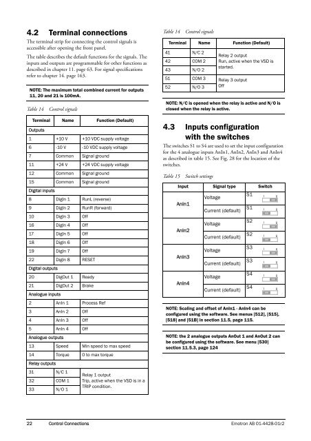
4.2 Terminal connections<br />
The terminal strip for connecting the control signals is<br />
accessible after opening the front panel.<br />
The table describes the default functions for the signals. The<br />
inputs and outputs are programmable for other functions as<br />
described in chapter 11. page 63. For signal specifications<br />
refer to chapter 14. page 163.<br />
NOTE: The maximum total combined current for outputs<br />
11, 20 and 21 is 100mA.<br />
Table 14<br />
Control signals<br />
Terminal Name Function (Default)<br />
Outputs<br />
1 +10 V +10 VDC supply voltage<br />
6 -10 V -10 VDC supply voltage<br />
7 Common Signal ground<br />
11 +24 V +24 VDC supply voltage<br />
12 Common Signal ground<br />
15 Common Signal ground<br />
Digital inputs<br />
8 DigIn 1 RunL (reverse)<br />
9 DigIn 2 RunR (forward)<br />
10 DigIn 3 Off<br />
16 DigIn 4 Off<br />
17 DigIn 5 Off<br />
18 DigIn 6 Off<br />
19 DigIn 7 Off<br />
22 DigIn 8 RESET<br />
Digital outputs<br />
20 DigOut 1 Ready<br />
21 DigOut 2 Brake<br />
Analogue inputs<br />
2 AnIn 1 Process Ref<br />
3 AnIn 2 Off<br />
4 AnIn 3 Off<br />
5 AnIn 4 Off<br />
Analogue outputs<br />
13 <strong>Speed</strong> Min speed to max speed<br />
14 Torque 0 to max torque<br />
Relay outputs<br />
31 N/C 1<br />
Relay 1 output<br />
32 COM 1 Trip, active when the VSD is in a<br />
33 N/O 1<br />
TRIP condition.<br />
Table 14<br />
41 N/C 2<br />
42 COM 2<br />
43 N/O 2<br />
Relay 2 output<br />
Run, active when the VSD is<br />
started.<br />
51 COM 3 Relay 3 output<br />
52 N/O 3 Off<br />
NOTE: N/C is opened when the relay is active and N/O is<br />
closed when the relay is active.<br />
4.3 Inputs configuration<br />
with the switches<br />
The switches S1 to S4 are used to set the input configuration<br />
for the 4 analogue inputs AnIn1, AnIn2, AnIn3 and AnIn4<br />
as described in table 15. See Fig. 28 for the location of the<br />
switches.<br />
Table 15<br />
Switch settings<br />
Input Signal type Switch<br />
AnIn1<br />
AnIn2<br />
AnIn3<br />
AnIn4<br />
Control signals<br />
Terminal Name Function (Default)<br />
Voltage<br />
Current (default)<br />
Voltage<br />
Current (default)<br />
Voltage<br />
Current (default)<br />
Voltage<br />
Current (default)<br />
S1<br />
S1<br />
S2<br />
S2<br />
S3<br />
S3<br />
S4<br />
S4<br />
NOTE: Scaling and offset of AnIn1 - AnIn4 can be<br />
configured using the software. See menus [512], [515],<br />
[518] and [51B] in section 11.5, page 115.<br />
NOTE: the 2 analogue outputs AnOut 1 and AnOut 2 can<br />
be configured using the software. See menu [530]<br />
section 11.5.3, page 124<br />
I<br />
I<br />
I<br />
I<br />
I<br />
I<br />
I<br />
I<br />
U<br />
U<br />
U<br />
U<br />
U<br />
U<br />
U<br />
U<br />
22 Control Connections <strong>Emotron</strong> AB 01-4428-01r2


