


Create successful ePaper yourself
Turn your PDF publications into a flip-book with our unique Google optimized e-Paper software.
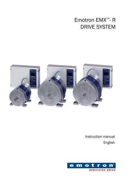
<strong>Emotron</strong> EMX - R<br />
<strong>DRIVE</strong> <strong>SYSTEM</strong><br />
Instruction manual<br />
English
Valid for the following models:<br />
EMX-R-15S<br />
EMX-R-15E<br />
EMX-R-25S<br />
EMX-R-25E<br />
EMX-R-35S<br />
EMX-R-35E<br />
Software version 2.x<br />
<strong>Emotron</strong> EMX -R<br />
<strong>DRIVE</strong> <strong>SYSTEM</strong><br />
INSTRUCTION MANUAL - English<br />
Document number: 01-3333-01<br />
Edition: r3<br />
Date of release: 2010-08-01<br />
© Copyright <strong>Emotron</strong> AB 2005 - 2010<br />
<strong>Emotron</strong> retain the right to change specifications and<br />
illustrations in the text, without prior notification. The<br />
contents of this document may not be copied without the<br />
explicit permission of <strong>Emotron</strong> AB.
The product is protected as follows:<br />
Patents: US 6 628 100; SE 9902821-9<br />
SE 0100814-3; SE 0100814-3; EP 1 366 346; US 7 083 544<br />
Registered design: US 462 937; DE 400 05 393.4; SE 66 630
Safety instructions<br />
During installation<br />
• Read the instruction manual completely before installation and commissioning.<br />
• The installation must be carried out by qualified personnel.<br />
• General conditions and regulations for the installation and operation of<br />
electrical machinery must be observed.<br />
• Measures to protect against personal injury and damage to the machine<br />
must be taken following local rules and regulations.<br />
• The drive system EMX-R is intended for permanent installation.<br />
• Cables may not be connected or disconnected while the supply voltage is<br />
on.<br />
• Check that the equipment is correctly connected before it is taken into use,<br />
see the instructions in the chapter on Mounting/Connection.<br />
• Faults that arise due to faulty installation or operation are not covered by the<br />
guarantee.<br />
During operation<br />
• Measurements in the control unit, during operation, must only be carried<br />
out on the terminals and only by authorized personnel. NOTE! Great care<br />
must be taken.<br />
• The units may not be opened or disassembled during operation.<br />
During disassembly and scrapping<br />
• The product is designed to comply with the RoHS directive, and shall be<br />
handled and recycled in accordance with local legislations.<br />
<strong>Emotron</strong> AB 01-3333-01r3
<strong>Emotron</strong> AB 01-3333-01r3
Contents<br />
1. Description.................................................................................. 3<br />
1.1 Introduction................................................................................................. 3<br />
1.2 Product range ............................................................................................. 4<br />
1.3 Operating indicators / built-in functions ................................................... 5<br />
1.3.1 Automatic purging mode / holding torque................................................ 6<br />
1.3.2 Rotation monitor (DIP switch 4)................................................................. 7<br />
1.3.3 Protection of the control unit ..................................................................... 8<br />
2. Mounting/connection.............................................................. 11<br />
2.1 Mounting .................................................................................................. 11<br />
2.1.1 External sensor for rotation monitor (option) ........................................ 12<br />
2.2 Connection ............................................................................................... 12<br />
2.2.1 When switching off .................................................................................. 13<br />
2.2.2 Recommendations with respect to EMC................................................ 13<br />
2.2.3 Priority switch / defrosting / manual control......................................... 14<br />
2.2.4 Manual control using a 10 kOhm potentiometer .................................. 14<br />
2.2.5 Test switch ............................................................................................... 14<br />
2.2.6 Choice of maximum speed ..................................................................... 16<br />
2.2.7 Setting DIP switches................................................................................ 17<br />
2.2.8 Speed controller ...................................................................................... 18<br />
2.2.9 Parallel connection.................................................................................. 18<br />
2.2.10 Heat recovery on cooling – summer/winter switch............................... 19<br />
2.2.11 Analogue output signal (only available on Model E) ............................. 19<br />
2.2.12 Potentiometer with low resistance, 100 Ohm to 5 kOhm<br />
(only available on Model E)..................................................................... 19<br />
3. Maintenance/troubleshooting................................................ 21<br />
3.1 Maintenance ............................................................................................ 21<br />
3.2 Motor diagnosis ....................................................................................... 21<br />
3.3 Troubleshooting ....................................................................................... 22<br />
4. Technical data ......................................................................... 25<br />
<strong>Emotron</strong> AB 01-3333-01r3 1
4.1 The drive system’s operation using different control signals................ 26<br />
4.2 Choice for sizes of drive system and belt pulley .................................... 29<br />
4.3 Accessories and documentation ............................................................ 30<br />
5. Appendix ................................................................................... 31<br />
2 <strong>Emotron</strong> AB 01-3333-01r3
1. Description<br />
1.1 Introduction<br />
<strong>Emotron</strong> EMX-R is a series of speed controlled drive systems specially designed<br />
for driving rotary heat exchangers. The drive system consist of a motor and its<br />
associated control unit.<br />
EMX-R completely replaces drive systems EMS-VVX 1, 2-4N, 2-4N/ET and<br />
2-4EM as well as the drive systems EMS-VVX 15, 25 and 35. All mentioned<br />
drive systems have completely been replaced by EMX-R.<br />
The drive system <strong>Emotron</strong> EMX-R is based, like its predecessor, on the<br />
SR-motors (SR=Switched Reluctance). These motors make it possible to drive<br />
heat exchanger rotors up to 3.5 metres in diameter without gears.<br />
Heat exchanger rotor<br />
Control unit<br />
Motor<br />
10-F08<br />
Fig. 1<br />
<strong>Emotron</strong> Motor and Control unit for rotary heat exchangers.<br />
<strong>Emotron</strong> AB 01-3333-01r3 Description 3
1.2 Product range<br />
EMX-R is available in three sizes for heat exchanger rotors up to around 3.5 m.<br />
They come in sizes 15, 25 and 35 (for other rotor sizes, please contact the local<br />
distributor or <strong>Emotron</strong> AB). The control unit sizes are dedicated to the motor<br />
sizes. Control unit EMX-R-15S(or E) could only work with motor<br />
EMX-R-15M and so on.<br />
The control unit is available in two versions, S and E, where Model E has an<br />
extra circuit board for increased functionality.<br />
Model<br />
EMX-R- 15S<br />
EMX-R- 15E<br />
EMX-R- 25S<br />
EMX-R- 25E<br />
EMX-R- 35S<br />
EMX-R- 35E<br />
Operating Indicator<br />
Two LEDs indicating red or green<br />
LED display<br />
Two LEDs indicating red or green<br />
LED display<br />
Two LEDs indicating red or green<br />
LED display<br />
Max heat exchanger<br />
rotor diameter (mm)<br />
1500<br />
2500<br />
3500<br />
Built-in functions included in the Model S are:<br />
• Automatic purging operation<br />
• Rotation monitor - integrated electronics or with external rotation sensor<br />
• Alarm relay<br />
• Test switch<br />
• Priority switch/defrosting<br />
• Heat recovery on cooling with external differential thermostat<br />
In addition to the functions included in Model S, the Model E includes:<br />
• Display of the rotor speed in rpm when the external rotation sensor is connected.<br />
• Analogue output signal proportional to the speed of the motor.<br />
• Heat recovery on cooling with external temperature sensors.<br />
• Input for potentiometer with low resistance, 100 Ohm to 5 kOhm.<br />
• Prepared for serial communication.<br />
4 Description <strong>Emotron</strong> AB 01-3333-01r3
1.3 Operating indicators / built-in functions<br />
Two LEDs, one red and one green, are used on the Model S for indication,<br />
while the Model E has an LED display as follows:<br />
Table 1<br />
Operating indication – Model S<br />
Slow flashing – Purging mode/Low control signal<br />
Green<br />
Red<br />
Rapid flashing – Operation, the motor rotates continuously<br />
Lit for two seconds – Magnet passing rotation sensor<br />
Lit - RotoSens measures the load on the motor during acceleration<br />
Lit or flashing LED indicates alarm, see also the chapter on troubleshooting<br />
Table 2<br />
Operating indication – Model E<br />
Purging mode. Low control signal<br />
The speed of the rotor in rpm. At start a speed is displayed according to<br />
the gear ratio rotor/motor = 1:25. After 2 pulses from the rotation<br />
monitor, the correct speed of the rotor is displayed. Range 0.2–99 rpm.<br />
RotoSens is selected using the DIP-switch (4) and with no rotation<br />
sensor connected<br />
Lit for two seconds when the magnet passes the rotation sensor<br />
RotoSens measures the load on the motor during acceleration<br />
Summer operation/heat recovery on cooling<br />
No rotation monitor - DIP 4 in the OFF position and jumper between<br />
terminal 31-32<br />
An alarm is indicated by the letter F followed by a number. See also the<br />
chapter on troubleshooting.<br />
<strong>Emotron</strong> AB 01-3333-01r3 Description 5
1.3.1 Automatic purging mode / holding torque<br />
When the control signal is low,
1.3.2 Rotation monitor (DIP switch 4)<br />
Two different rotation monitors can be selected. The first, RotoSens, which is<br />
an integrated electronic rotation monitor, and secondly a rotation monitor<br />
using an external rotation sensor.<br />
RotoSens uses the motor as the sensor. By allowing the control unit to measure<br />
the load on the motor, you can determine whether the drive belt has broken.<br />
When the drive belt has broken, the motor load will be low. As the heat<br />
exchanger rotors which rotate very easily also give a low load on the motor, it is<br />
necessary to also measure the load during acceleration - you then get a measurement<br />
of the rotor’s torque of inertia. After 2 minutes of operation at a low load,<br />
a load measurement is made during acceleration. If the drive belt is broken an<br />
alarm is given, if it is undamaged the load measurement during acceleration is<br />
repeated again after 24 hours. In cleaning mode, measurement during acceleration<br />
is made once every 24 hours.<br />
The rotation monitor with external rotation sensor requires a magnet fitted on<br />
the periphery of the rotor. The magnet activates the external rotation sensor<br />
once every revolution. Should, for example, a belt break and the rotor stops, the<br />
pulses cease and an alarm is given. The time until the alarm is given is speed<br />
dependent and is 24 seconds at max. speed, 20 minutes at min. speed and about<br />
8 hours in purge mode.<br />
NOTE: In order to use RotoSens the load on the motor should not be too low.<br />
The minimum diameter for the heat exchanger rotor and belt pulley for each<br />
size of the drive system must be:<br />
EMX-R-15: Belt pulley 63 mm, heat exchanger rotor diameter 630 mm<br />
EMX-R-25: Belt pulley 63 mm, heat exchanger rotor diameter 1200 mm<br />
EMX-R-35: Belt pulley 100 mm, heat exchanger rotor diameter 2000<br />
mm<br />
If the belt pulley or heat exchanger rotor are smaller, RotoSens can not be<br />
used, however, the rotation monitor with sensor can always be used.<br />
The rotation monitors give alarms through operating indications (display or<br />
LED) and via the alarm relay (external signal). The motor does not stop with<br />
this alarm.<br />
Following rotation monitor functions are available:<br />
• DIP switch 4( see chapter 2.2.7 page 17)in position “OFF” (downwards),<br />
<strong>Emotron</strong> AB 01-3333-01r3 Description 7
means the built-in electronic rotation monitor RotoSens is connected.<br />
• DIP switch 4 in position “ON”(uppwards), means rotation monitor uses an<br />
external rotation sensor.<br />
• No rotation monitoring, DIP-switch 4 also must be set in position “OFF”,<br />
and a jumper must be fitted between terminals 31 and 32 (“oF” is now indicated<br />
in the display on Model E).<br />
1.3.3 Protection of the control unit<br />
The control unit is protected by monitoring for both over-voltage and undervoltage.<br />
If the supply voltage goes over or under the allowed limits, an alarm is<br />
triggered and the motor stops. The motor starts again automatically when the<br />
supply voltage returns to its normal value. The alarm is automatically reset.<br />
The control unit has built-in motor protection that protects against overloading,<br />
and external motor protection is not required. Power supply to the motor is<br />
cut in the event of overload. In order to restart the drive system, the supply voltage<br />
to the control unit must be temporarily disconnected for at least 5 seconds.<br />
Built-in short circuit protection protects against short circuits between the<br />
phases of the motor and between the phases and earth.<br />
Table 3<br />
Protection and alarm functions<br />
Protective<br />
function<br />
External alarm<br />
with alarm relay<br />
Restart<br />
Alarm reset<br />
Supply fault, overvoltage<br />
Supply fault,<br />
under-voltage<br />
Yes, immediately<br />
Automatic<br />
Automatic<br />
Pre-alarm, rotation<br />
monitor<br />
Rotation<br />
monitor<br />
No<br />
Yes<br />
Motor not stopped<br />
1)<br />
Pre-alarm, motor<br />
protection/overload<br />
No<br />
The system tries<br />
to reset three<br />
times<br />
Automatic<br />
8 Description <strong>Emotron</strong> AB 01-3333-01r3
Table 3<br />
Protection and alarm functions<br />
Protective<br />
function<br />
Motor protection/<br />
overload<br />
Short circuit<br />
External alarm<br />
with alarm relay<br />
Yes, immediately<br />
Restart<br />
Manual, disconnect<br />
and reconnect<br />
power<br />
supply<br />
1) RotoSens - manual, disconnect and reconnect the power supply.<br />
Rotation monitor with sensor - automatic.<br />
Alarm reset<br />
Manual, disconnect<br />
and reconnect<br />
power<br />
supply<br />
<strong>Emotron</strong> AB 01-3333-01r3 Description 9
10 Description <strong>Emotron</strong> AB 01-3333-01r3
2. Mounting/connection<br />
2.1 Mounting<br />
Both the motor and the control unit are usually mounted in the heat exchanger<br />
housing. In this way, they do not occupy any space outside of the heat<br />
exchanger housing and are well protected during transport. Furthermore, it is<br />
often advantageous from the point of view of interference (EMC) to place the<br />
motor and control unit in the rotor housing. The motor is usually mounted on<br />
a sprung motor support when a V-belt is used. In this way, problems arising if<br />
non-circular rotors are used can be prevented. Vibration dampers should be<br />
mounted between the motor and the motor support so that any vibration from<br />
the motor is not transmitted to the rotor housing.<br />
Heat exchanger<br />
Control unit<br />
Motor<br />
10-F08<br />
Fig. 2<br />
Heat exchanger rotor and drive system<br />
<strong>Emotron</strong> AB 01-3333-01r3 Mounting/connection 11
2.1.1 External sensor for rotation monitor (option)<br />
The magnet for the rotation sensor is mounted onto the periphery of the heat<br />
exchanger. If the heat exchanger rotor cover is magnetic, the magnet must be<br />
insulated from the cover. The rotation sensor is mounted such that the magnet<br />
passes at a distance of 5–8 mm, see below.<br />
Magnet<br />
Heat exchanger rotor<br />
Rotation sensor<br />
5-8 mm<br />
Fig. 3<br />
Mounting of the rotation sensor<br />
2.2 Connection<br />
WARNING! Residual voltage remains for up to 1 minute after<br />
disconnection of the supply voltage.<br />
The motor is delivered with a fixed connected motor cable to simplify installation<br />
of the drive system. The length of the cable is 2.0 m for EMX-R 15M and<br />
2.5 m for EMX-R 25M and EMX-R 35M.<br />
In order to secure the function of the EMX drive system, do not change the<br />
length of the motor cable. This could interfere with the electronic tachometer<br />
that is built into the system.<br />
An external slow-blow fuse rated at
A safety switch is to be installed between the mains supply and the control unit.<br />
An alarm for loss of power is given if the mains supply is disconnected.<br />
WARNING! No switch is allowed between the motor and the control<br />
unit.<br />
2.2.1 When switching off<br />
When it is desired to switch off the heat exchanger, for example at night, this<br />
can be done using a relay connected in series with the control signal. This relay<br />
interrupts the signal to control signal terminal number 33. In this way, no alarm<br />
about interruption of power supply is given. The control signal can of course<br />
also be reduced to its minimum value, in order to achieve the same result. If the<br />
control signal is low or absent the drive system switches to purging mode.<br />
2.2.2 Recommendations with respect to EMC<br />
In order to fulfil the European EMC Directive 89/336/ECC regarding electromagnetic<br />
compatibility, the following precautions must be taken:<br />
• The motor cable must be mounted as close to the heat exchanger housing as<br />
possible. If the cable is too long, the excess should be collected together in<br />
the form of, for example, a figure “8”. The area enclosed by the cable should<br />
be as small as possible. Electrical tape or cable ties can be used to achieve<br />
this.<br />
WRONG<br />
RIGHT<br />
Fig. 4 Excess motor cable should be arranged such that the area enclosed is as<br />
small as possible<br />
Special EMC couplings/glands are not necessary. An EMC filter is built into all<br />
EMX-R models.<br />
<strong>Emotron</strong> AB 01-3333-01r3 Mounting/connection 13
2.2.3 Priority switch / defrosting / manual control<br />
A preselected speed of rotation can be specified by a potential-free connection<br />
between the priority inputs 34–35. When terminal 34 is connected to terminal<br />
35, the speed is determined by the priority potentiometer, which is located next<br />
to the DIP switches in the control unit. The priority switch has higher priority<br />
than the summer/winter switch (only available on Model E) and the control signal.<br />
The switch can be used, for example, when cleaning the rotor, defrosting using<br />
an external differential pressostat or for manual control of the speed of rotation.<br />
2.2.4 Manual control using a 10 kOhm potentiometer<br />
It is simple to control the drive system manually by using a 10 kOhm potentiometer<br />
connected as shown in the figure.<br />
Control unit<br />
33<br />
34<br />
10 kOhm<br />
37<br />
2.2.5 Test switch<br />
The control unit is equipped with a test switch, placed under the cover between<br />
terminals 37 and 41. When this switch is in the “ON” position, the motor softstarts<br />
and the speed increases to the maximum, independently of other signal<br />
sources. When in the “OFF” position (down), the test switch is not operational.<br />
The test switch can also be used to run the motor at maximum speed if, for<br />
example, an external control signal is missing.<br />
14 Mounting/connection <strong>Emotron</strong> AB 01-3333-01r3
8<br />
I U<br />
J1<br />
51<br />
52 53 54 55 56 57 58<br />
ON<br />
1 2 3456 78<br />
ON<br />
Extra circuit board in<br />
the Model E with LEDdisplay,<br />
E-terminals 51-58<br />
and jumper J1<br />
L N 1 2 3 4 5 6 31 32 33 34 35 36 37 41 42 43<br />
10-F05<br />
1 2 34 5 6 7<br />
Fig. 5<br />
Location of terminals, etc.<br />
No.<br />
Designation<br />
1 Supply terminal<br />
2 Motor terminal<br />
3 Priority potentiometer<br />
4 Control signal terminal<br />
5 DIP switch<br />
6 Test switch<br />
7 Alarm terminal<br />
8 Operating indicator for Model S, two LEDS<br />
<strong>Emotron</strong> AB 01-3333-01r3 Mounting/connection 15
Extra circuit board in<br />
I U<br />
model E<br />
J1<br />
51 52 53 54 55 56 57 58<br />
Heat recovery on cooling<br />
51-52 incoming air sensor<br />
Potentiometer<br />
control<br />
100 W - 5 kW<br />
51-53 exhaust air sensor Analogue output signal<br />
0-10V/20mA<br />
Modell S and S E<br />
Alarm relay 42-43<br />
closed on alarm<br />
L N<br />
1 2 3 4 5 6<br />
31 32 33 34 35 36 37<br />
41 42 43<br />
Safety switch<br />
L N<br />
M<br />
Rotation<br />
sensor<br />
Control signal<br />
Heat recovery on cooling<br />
Priority switch<br />
10-F11<br />
Manual control connection.<br />
see Chapter 2.2.4<br />
33 34 35 36 37<br />
10 k Ω<br />
Fig. 6<br />
Wiring diagram<br />
2.2.6 Choice of maximum speed<br />
The maximum speed can be limited to 80% (200 rpm) or 60% (150 rpm). This<br />
function is primarily intended for use with rotors smaller than 1.3 m, when it is<br />
desired to limit the speed of rotation and/or when using larger belt pulleys.<br />
16 Mounting/connection <strong>Emotron</strong> AB 01-3333-01r3
2.2.7 Setting DIP switches<br />
Control signal<br />
ON<br />
0-10 V V-belt<br />
Speed controller<br />
ON<br />
1 2 3<br />
5<br />
ON<br />
2-10V Other belts<br />
ON<br />
1 2 3<br />
5<br />
0-20V<br />
4-20mA<br />
ON<br />
1 2 3<br />
ON<br />
Clockwise<br />
Direction of rotation<br />
ON<br />
1 2 3<br />
6<br />
0-20mA<br />
ON<br />
Counterclockwise<br />
ON<br />
1 2 3<br />
6<br />
Rotation monitor<br />
Maximum speed<br />
With<br />
external<br />
rotation sensor<br />
ON<br />
4<br />
100%<br />
ON<br />
7 8<br />
ON<br />
RotoSens 80%<br />
ON<br />
4<br />
7 8<br />
60%<br />
ON<br />
7 8<br />
WARNING! Disconnect the voltage supply before changing the DIP<br />
switch settings.<br />
<strong>Emotron</strong> AB 01-3333-01r3 Mounting/connection 17
2.2.8 Speed controller<br />
DIP switch 5 on the control unit can be used to select between two speed controllers.<br />
One controller provides gentler operation and is used if resilient belts<br />
such as round belts, flat belts and resilient V-belts are fitted. In this case DIP<br />
switch 5 should be set “OFF”. The other controller is faster and stiffer, and is<br />
intended for use with stiff belts such as V-belts and homogenous round belts. In<br />
this case DIP switch 5 should be set “ON”.<br />
If the stiffer controller is not adequate for smooth operation when the max.<br />
speed is set to 100%, an even stiffer and faster controller can be selected by setting<br />
DIP switches 5 and 7 “ON” and setting DIP switch 8 “OFF”.<br />
ON<br />
5 7 8<br />
2.2.9 Parallel connection<br />
If several rotary heat exchangers are to be used in parallel using one control signal<br />
or sensor, each heat exchanger rotor must be equipped with its own drive<br />
system (motor and control unit).<br />
The control signal is connected to the first drive system according to the<br />
instructions for connection. The other control units are connected by connecting<br />
terminals 33 and 34 of the other control units to terminals 33 and 34,<br />
respectively, on the first control unit.<br />
The DIP switches on the first control unit are set as described in “Setting DIP<br />
switches”. DIP switch 1 and DIP switch 3 on the other control units are set as<br />
described in “Setting DIP switches”, while DIP switch 2 is always set as<br />
described below:<br />
ON<br />
2<br />
The control units give individual alarms. The alarm outputs can be connected<br />
in parallel or in series in order to obtain a collective alarm.<br />
Model E can also use the analogue output signal in order to control other drive<br />
systems. Terminals 54(-) and 55(+) are connected to terminals 34(–) and 33(+),<br />
18 Mounting/connection <strong>Emotron</strong> AB 01-3333-01r3
espectively. The DIP switches on all control units are set as described in “Setting<br />
DIP switches”.<br />
2.2.10 Heat recovery on cooling – summer/winter switch<br />
Heat recovery on cooling refers to the mode of operation when the incoming air<br />
temperature exceeds the exhaust air temperature. By driving the rotary heat<br />
exchanger at maximum speed, a cooling effect is achieved on the incoming air.<br />
The heat recovery on cooling function is most simply obtained by using an<br />
external regulator which has this function built-in. EMX-R is then controlled<br />
by a control signal, e.g. 0–10 V.<br />
If for example, an external regulator is already installed, you can obtain the heat<br />
recovery on cooling function by directly connecting a separate differential thermostat<br />
to EMX-R, terminals 36–37<br />
Model E has a built-in differential thermostat. This makes it possible to connect<br />
two NTC sensors of resistance 2000 Ohm (for example EGL 511), one in the<br />
incoming air duct and one in the exhaust air duct, directly to EMX-R, terminals<br />
51–53. If the exhaust air is colder than the incoming air, the rotor rotates at its<br />
maximum speed, and cooling is recovered. If the exhaust air is warmer than the<br />
incoming air (as is normally the case) the speed is controlled by the control signal,<br />
and heat is recovered.<br />
2.2.11 Analogue output signal (only available on Model E)<br />
The output signal, 0–20 mA or 0–10 V, is proportional to the speed of the<br />
motor. Maximum value, 20 mA or 10 V, is always obtained at the selected max.<br />
speed (60, 80 or 100% of the motor’s maximum rpm). The choice between the<br />
0–20 mA output signal and the 0–10 V output signal is made with jumper J1<br />
positioned behind the control terminals 51–58.<br />
2.2.12 Potentiometer with low resistance, 100 Ohm to 5<br />
kOhm (only available on Model E)<br />
When control is provided by an external potentiometer with a total resistance<br />
value between 100 Ohm and 5 kOhm, the three leads are connected to terminals<br />
56–58. DIP switches 1–3 are set in the same way as for a control signal of<br />
0–10 V.<br />
<strong>Emotron</strong> AB 01-3333-01r3 Mounting/connection 19
20 Mounting/connection <strong>Emotron</strong> AB 01-3333-01r3
3. Maintenance/troubleshooting<br />
WARNING! Residual voltage remains for up to 1 minute after<br />
disconnection of the supply voltage. The test switch and the DIP<br />
switches may only be adjusted when the supply voltage has been<br />
disconnected.<br />
3.1 Maintenance<br />
The motor and the controller do not normally require any maintenance. However,<br />
it should be regularly checked that the cabling is not damaged and that all<br />
fixing screws are securely tightened.<br />
3.2 Motor diagnosis<br />
Disconnect the supply voltage. Disconnect the motor cables from the control<br />
unit. Measure the motor resistance between 1–2, 3–4 and 5–6. The values<br />
should be:<br />
15M: 30–90 Ohm; 25M: 5–15 Ohm; 35M: 5–15 Ohm<br />
The resistance should not differ by more than 5 Ohm between the phases for<br />
15M, and by no more than 2 Ohm for 25M/35M. Also check the insulation<br />
resistance between 1–3, 1–5, 3–5, 1–earth, 3–earth and 5–earth.<br />
Note! When checking the insulation resistance, it is important to turn the<br />
motor shaft slowly (at least one complete turn) in order to get a correct<br />
measurement.<br />
<strong>Emotron</strong> AB 01-3333-01r3 Maintenance/troubleshooting 21
3.3 Troubleshooting<br />
Check that the equipment has been correctly installed, i.e. that the cables are<br />
properly stripped, that there are no loose cables, etc., and check that the DIP<br />
switches are correctly set. Check that Control unit and motor have the correct<br />
size, Control unit EMX-R-15S(or E) could only work with motor<br />
EMX-R-15M and so on.<br />
It is always possible to test run the drive system using the TEST switch located<br />
under the cover next to terminal 37, see Fig. 5, page 15. The switch has two<br />
fixed positions, when it is in the up position, the motor accelerates to its maximum<br />
speed independent of the control signal, and when it is in the down position<br />
the rotation speed is controlled by the control signal.<br />
If the motor does not reach maximum speed or respond to the control signal,<br />
check DIP switches 1–3 and 7 and 8. If the heat exchanger rotates in the wrong<br />
direction, change the setting of DIP switch 6. Reset, vibration, noise and builtin<br />
protection are described in the chapters Description and Mounting/Connection.<br />
If the control unit is to be exchanged, the complete covered box containing the<br />
circuit boards must be exchanged.<br />
22 Maintenance/troubleshooting <strong>Emotron</strong> AB 01-3333-01r3
Table 4<br />
Troubleshooting<br />
Green LED<br />
flashes<br />
slowly<br />
Alarm indication<br />
S E Fault<br />
Red and<br />
green LED<br />
flash rapidly<br />
Red LED<br />
flashes<br />
rapidly<br />
Red LED is lit<br />
and green<br />
LED flashes<br />
rapidly<br />
Purging/<br />
low control<br />
signal<br />
Pre-alarm<br />
rotation<br />
monitor<br />
Rotation<br />
monitor<br />
Pre-alarm,<br />
overload/<br />
motor<br />
protection<br />
Fault condition/Action required<br />
Check the drive system with the test<br />
switch located next to terminal 37. The<br />
motor should accelerate to its maximum<br />
speed. If the motor does accelerate to the<br />
maximum speed when the test switch is<br />
activated, the fault is external.<br />
Is the control signal between 33(+) and<br />
34 (-) present?<br />
Have + and - been swapped?<br />
The drive system has switched to a softer<br />
speed controller because the motor shaft<br />
is jerking sharply. Check that the drive belt<br />
is not slipping on the pulley.<br />
The exchanger rotor does not rotate;<br />
check the drive belt.<br />
The rotor rotates; check that the indication<br />
is given when the magnet passes the rotation<br />
sensor, see the section Operating<br />
indicators, if not replace the rotation sensor.<br />
If RotoSens is used, check that the<br />
rotor or belt pulley are not smaller than<br />
630 mm respective 63 mm.<br />
Check function of the rotation sensor:<br />
Measure with a Multimeter between terminal<br />
31 and 32, correct sensor<br />
measures < 1 V when the magnet passes<br />
the sensor.<br />
The motor protection has been activated<br />
due to excessive load. After a cool-down<br />
period of 10 minutes the system restarts<br />
automatically. If the overload protection<br />
trips 3 times within 120 minutes the drive<br />
system will be shut down, see also overload<br />
(F5).<br />
<strong>Emotron</strong> AB 01-3333-01r3 Maintenance/troubleshooting 23
Table 4<br />
Troubleshooting<br />
Red LED is lit<br />
No LED lit -<br />
Red and<br />
green flash<br />
slowly and<br />
alternately<br />
Red and<br />
green LED<br />
flash rapidly<br />
and alternately<br />
Red LED<br />
flashes<br />
slowly<br />
Alarm indication<br />
S E Fault<br />
Overload/<br />
motor<br />
protection<br />
Supply voltage<br />
missing<br />
Overvoltage<br />
Undervoltage<br />
Earth fault in<br />
the motor<br />
Short circuit<br />
in the motor<br />
Circuit break<br />
in the motor<br />
Fault condition/Action required<br />
The motor protection has been activated<br />
due to excessive load. Check that the<br />
motor cables are connected correctly, see<br />
the chapter on Mounting/Connection.<br />
Check also that the rotor runs freely and<br />
that the diameters of the rotor and pulley<br />
is according to Table 9 page 29. If wrong<br />
pulley is mounted, change pulley or<br />
change max. speed with DIP-switch 7 and<br />
8 acc. to chapter 2.2.7 page 17.<br />
If the fault remains, carry out motor diagnosis.<br />
Replace the motor if it is faulty. If<br />
the fault does not lie within the motor,<br />
replace the control unit.<br />
Check that 230 VAC ±15% is connected to<br />
the supply terminal.<br />
The supply voltage exceeds 264 VAC.<br />
The supply voltage lies below 196 VAC.<br />
Disconnect the supply voltage, check the<br />
connection of the motor cable and check<br />
that the correct motor is connected. If the<br />
fault remains, carry out motor diagnosis.<br />
If the motor is faulty, replace it. If the fault<br />
does not lie within the motor, replace the<br />
control unit.<br />
Motor runs<br />
irregularly<br />
Check belt tension.<br />
If DIP-switch 5 = OFF and there is a<br />
stiff belt mounted, change speed<br />
controller by setting DIP-switch to ON.<br />
24 Maintenance/troubleshooting <strong>Emotron</strong> AB 01-3333-01r3
4. Technical data<br />
Table 5<br />
Technical data<br />
Function<br />
EMX-R<br />
15 25 35<br />
Output data<br />
Input data<br />
General<br />
Rotation speed [rpm] 5-250<br />
Torque 1) [Nm] 1.5 4 6<br />
Power [W] 40 100 160<br />
Direction of rotation<br />
Selectable<br />
Purging mode<br />
Built-in function<br />
Motor protection<br />
Built-in function<br />
Soft start and stop [s] 15/15 25/25 35/35<br />
Alarm output<br />
Alternating contact, max 5 A 230 VAC<br />
Supply voltage<br />
230 VAC ±15%, 50/60 Hz<br />
Current [A] 0.7 1.3 1.7<br />
0–10 V, 2–10 V, 0–20V phase cut,<br />
Control signal<br />
0–20 mA, 4–20 mA,<br />
10 kOhm potentiometer<br />
Protection class IP 54<br />
Weight, control unit [kg] 1.4 1.7<br />
Weight, motor [kg] 5 8 11<br />
Terminals<br />
1 pc M12 and 4 pc M20 (glands)<br />
Ambient temperature<br />
-30 - +40º C<br />
Tachometer<br />
Electronic tachometer, tachometer cable is<br />
not needed<br />
EMC, Emission EN 61000-6-3/EN 61000-6-4<br />
EMC, Immunity EN 61000-6-2<br />
1) Torque is constant over entire speed range.<br />
<strong>Emotron</strong> AB 01-3333-01r3 Technical data 25
4.1 The drive system’s operation using<br />
different control signals<br />
The drive system has a built-in linearity function that gives a linear relationship<br />
between the control signal and the efficiency of the heat exchanger rotor, rather<br />
than having the speed of rotation proportional to the control signal. This provides<br />
good conditions for stable temperature control.<br />
Motor speed<br />
250<br />
200<br />
150<br />
[rpm]<br />
100%<br />
80%<br />
60%<br />
Purging<br />
2 rev./10 min.<br />
5<br />
Purging<br />
Control<br />
signal<br />
Max. Speed<br />
Control signal Purging Maximum speed<br />
0-10 V 1,5 V 9,7 V<br />
2-10 V 3 V 9,7 V<br />
0-20 V 3 V 19,4 V<br />
4-20 mA 6 mA 19,4 mA<br />
0-20 mA 3 mA 19,4 mA<br />
Table 6<br />
Motor model designations<br />
Article number Designation Notes<br />
01-2160-00 EMX-R-15M Cable 2.0 m<br />
01-2162-00 EMX-R-25M Cable 2.5 m<br />
01-2163-00 EMX-R-35M Cable 2.5 m<br />
26 Technical data <strong>Emotron</strong> AB 01-3333-01r3
F<br />
K1<br />
K<br />
K2<br />
FA<br />
FC<br />
FB<br />
LC<br />
HB<br />
HD<br />
H<br />
LA<br />
10-F06<br />
L<br />
M<br />
HA<br />
Fig. 7<br />
Table 7<br />
Motor dimensions<br />
Motor dimensions (mm)<br />
EMX-R F FA FB FC H HA HB HD<br />
15 88 96 10 7 56 8 119 134<br />
25 82 140 12 7 81 10 173 180<br />
35 109 140 12 7 81 10 173 180<br />
EMX-R K K1 K2 L LA LC M<br />
15 14j6 5h9 20 113 30 145 110<br />
25 14j6 5h9 20 114 35 152 160<br />
35 14j6 5h9 20 141 35 179 160<br />
<strong>Emotron</strong> AB 01-3333-01r3 Technical data 27
ø 4,5 (4x)<br />
Table 8<br />
Control unit model designations<br />
Article number<br />
01-2170-11 EMX-R-15S<br />
01-2171-11 EMX-R-15E<br />
01-2174-11 EMX-R-25S<br />
01-2175-11 EMX-R-25E<br />
01-2176-11 EMX-R-35S<br />
01-2177-11 EMX-R-35E<br />
Designation<br />
200<br />
150<br />
58<br />
6<br />
188<br />
113<br />
29,5<br />
10-F07<br />
Fig. 8<br />
Control unit dimensions (mm)<br />
28 Technical data <strong>Emotron</strong> AB 01-3333-01r3
4.2 Choice for sizes of drive system and belt<br />
pulley<br />
Table 9<br />
Choice of size for drive system and belt pulley<br />
Rotor<br />
diameter<br />
[mm]<br />
EMX-R<br />
model<br />
Belt pulley<br />
diameter<br />
[mm]<br />
Maximum speed<br />
of revolution<br />
[%]<br />
700 15 63 60 13.5<br />
700 15 30 100 10.7<br />
900 15 63 60 10.5<br />
900 15 40 100 11.1<br />
1100 15 63 80 11.5<br />
1100 15 50 100 11.4<br />
1300 15 71 80 10.9<br />
1300 15 63 100 12.1<br />
1500 15 71 100 11.8<br />
1700 25 80 100 11.8<br />
1900 25 80 100 10.5<br />
2100 25 100 100 11.9<br />
2300 25 100 100 10.9<br />
2500 25 100 100 10.0<br />
2700 35 118 100 10.9<br />
3100 35 140 100 11.3<br />
3500 35 140 100 10.0<br />
Rotor speed<br />
[rpm]<br />
NOTE: Higher rotor speeds than those given in the table above increase the<br />
loading and a larger drive system may be necessary. Tight rotor seals may<br />
also require the use of a larger size. Rotors that have a high capacity to<br />
absorb humidity, such as dehumidification rotors in desiccant cooling<br />
system requires a larger drive system, see separate documentation.<br />
<strong>Emotron</strong> AB 01-3333-01r3 Technical data 29
4.3 Accessories and documentation<br />
Table 10<br />
Accessories<br />
Article number<br />
Designation<br />
01-2184-00 Rotation sensor with magnet M12 x 75 mm<br />
01-3549-00 Rotation sensor with magnet M12 x 35 mm<br />
01-3660-00 Cable fixture for control unit 15-35<br />
01-2182-00 Mounting kit, expander type for motor 15-35<br />
01-2183-00 Mounting kit 2*M6 for motor 15-35<br />
01-2182-00 01-2183-00<br />
Fig. 9<br />
Table 11<br />
Mounting kits with vibration damping for motor<br />
Operating instructions<br />
Article number<br />
Designation<br />
01-3333-00 Swedish instruction manual<br />
01-3333-01 English instruction manual<br />
01-3333-02 German instruction manual<br />
01-3333-03 Dutch instruction manual<br />
01-3333-05 Danish instruction manual<br />
01-3333-06 Norwegian instruction manual<br />
01-3333-07 Finnish instruction manual<br />
01-3333-08 French instruction manual<br />
01-3333-13 Polish instruction manual<br />
30 Technical data <strong>Emotron</strong> AB 01-3333-01r3
5. Appendix<br />
Connection lable<br />
Model E (optional)<br />
I<br />
U<br />
1 2 3<br />
J1<br />
1-2: 0-20mA<br />
2-3: 0-10V<br />
51 52 53 54 55 56 57 58<br />
+<br />
51-52-53 Kylåtervinning, Heat recovery on cooling,<br />
Kälterückgewinnung<br />
54-55 Analog ut, Analogue out, Analog aus<br />
56-57-58 Pot. Styrning, Pot. Control, Pot. Betrieb 100ohm -<br />
5kohm<br />
STYRSIGNAL<br />
CONTROL SIGNAL<br />
STEUERSIGNAL<br />
ROTATIONSVAKT<br />
ROT. MONITOR<br />
ROT. GEBER<br />
REMTYP<br />
TYPE OF BELT<br />
RIEMENTYP<br />
ROT. RIKTNING<br />
ROT. DIRECTION<br />
DREHRICHTUNG<br />
MAX. VARVTAL<br />
MAX. RPM<br />
MAX. DREHZAHL<br />
0-10V<br />
Ja, Yes, Ja<br />
100%<br />
Model S<br />
ON<br />
1 2 3 4 5 6 7 8<br />
2-10V<br />
ON<br />
1 2 3 4 5 6 7 8<br />
Nej, No, Nein<br />
ON<br />
1 2 3 4 5 6 7 8<br />
ON<br />
1 2 3 4 5 6 7 8<br />
ON<br />
1 2 3 4 5 6 7 8<br />
80%<br />
ON<br />
ON<br />
ON<br />
ON<br />
ON<br />
1 2 3 4 5 6 7 8<br />
1 2 3 4 5 6 7 8<br />
1 2 3 4 5 6 7 8<br />
1 2 3 4 5 6 7 8<br />
1 2 3 4 5 6 7 8<br />
Restspänning<br />
Residual voltage<br />
Restspannung<br />
NÄT<br />
MAINS<br />
NETZ<br />
4-20mA<br />
ON<br />
MOTOR<br />
MOTOR<br />
MOTOR<br />
1 2 3 4 5 6 7 8<br />
31-32 Rotationsgivare, Rotation sensor,<br />
Rotationsgeber<br />
33-34 Styrsignal, Control signal,<br />
Steuersignal<br />
34-35 Prioritetomkopplare, Priority switch,<br />
Prioritätsschalter<br />
36-37 Kylåtervinning, Heat recovery on<br />
cooling, Kälterückgewinnung<br />
TEST PÅ<br />
TEST ON<br />
TEST EIN<br />
60%<br />
ON<br />
1 2 3 4 5 6 7 8<br />
LARM RELÄ<br />
ALARM RELAY<br />
ALARM RELAIS<br />
L N<br />
1 2 3 4 5 6 31 32 33 34 35 36 37<br />
41 42 43<br />
01-2271-00 R1<br />
L<br />
N<br />
+<br />
PRIORITETSPOT.<br />
PRIORITY POT.<br />
PRIORITÄT POT.<br />
TEST AV<br />
TEST OFF<br />
TEST AUS<br />
42-43 Slutande vid larm<br />
Closed on alarm<br />
Geschlossen bei Alarm<br />
<strong>Emotron</strong> AB 01-3333-01r3 Appendix 31
32 Appendix <strong>Emotron</strong> AB 01-3333-01r3
Model S<br />
EMX-R<br />
Model E<br />
EMX-R<br />
Långsamt blinkande - Renblåsningsdrift<br />
Snabbt blinkande - Drift<br />
Lyser i 2 s<br />
- Magneten passerar<br />
rotationsgivaren<br />
Slowly flashing<br />
Fast flashing<br />
Lit for 2 sec.<br />
- Cleaning operation<br />
- Operation<br />
- The magnet passes the<br />
rotation sensor<br />
Langsam blinkend - Intervallbetrieb<br />
Schnell blinkend - Betrieb<br />
Leuchtet 2 Sek. lang - Rotormagnet passiert<br />
Rotationsgeber<br />
RÖD RED ROT<br />
Blinkande<br />
- Rotationslarm<br />
Lyser<br />
- Överlast<br />
Flashing<br />
Lit<br />
Blinkend<br />
Leuchtet<br />
GRÖN GREEN GRÜN<br />
- Rotation alarm<br />
- Overload<br />
- Rotationsalarm<br />
- Überlast<br />
VARNING! WARNING! ACHTUNG!<br />
Bryt spänningen innan locket öppnas<br />
Turn off supply before removing cover<br />
Gerät vor dem Öffnen vom Netz trennen<br />
Integrerad elektr. rotationsvakt<br />
Integrated electr. rotation monitor<br />
Integrierter elektr. Rotationswächter<br />
Rotorvarvtal; Ext. rotationsgivare<br />
Rotor speed; Ext. rotation sensor<br />
Rotordrehzahl; Ext. Rotationsgeber<br />
Renblåsningsdrift<br />
Cleaning operation<br />
Intervallbetrieb<br />
Signal från extern rotationsgivare<br />
Signal from external rotation sensor<br />
Signal von externem Rotationsgeber<br />
Rotationslarm<br />
Rotation alarm<br />
Rotationsalarm<br />
Överlast<br />
Overload<br />
Überlast<br />
VARNING! WARNING! ACHTUNG!<br />
Bryt spänningen innan locket öppnas<br />
Turn off supply before removing cover<br />
Gerät vor dem Öffnen vom Netz trennen
<strong>Emotron</strong> AB, Mörsaregatan 12, SE-250 24 Helsingborg, Sweden<br />
Tel: +46 42 16 99 00, Fax: +46 42 16 99 49<br />
E-mail: info@emotron.se<br />
Internet: www.emotron.com<br />
<strong>Emotron</strong> AB 01-3333-01r3 2010-08-01


