You also want an ePaper? Increase the reach of your titles
YUMPU automatically turns print PDFs into web optimized ePapers that Google loves.
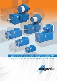
Precision Worm Gearboxes<br />
for Servomotors
2<br />
ZF-Duoplan 2K<br />
Two-speed Gearboxes<br />
ZF-Servoplan PG<br />
Servogearboxes<br />
ZF-Servoplan CG<br />
Compact Gearboxes<br />
ZF-Tiratron<br />
Hysteresis Brakes<br />
ZF-Ecolift<br />
Elevator Gearboxes<br />
ZF-Servoplan PGE<br />
Servogearboxes Economy<br />
Customer specific<br />
Gearboxes<br />
ZF-Servoplan WT<br />
Right Angle Gearboxes
3<br />
Precision in movement<br />
Our group has offered it’s customers a wide range of high<br />
quality power transmission components for a long period of<br />
time. Our extensive product portfolio includes gearboxes, brakes<br />
and clutches serving a variety of industries.<br />
Servoplan <strong>SWG</strong><br />
Servogearboxes<br />
Our geared products include: in-line servo gearboxes<br />
(ZF-Servoplan PG and PGE), right angle servo gearboxes<br />
(ZF-Servoplan WT and Servoplan <strong>SWG</strong>) and compact<br />
servo gearboxes (ZF-Servoplan CG) serving, among others,<br />
the general automation, packaging, material handling, machine<br />
tool and robotics industries. Our innovative two-speed gearbox<br />
(ZF-Duoplan) was developed for main spindle drives in<br />
machine tools, and a high efficiency planetary gearbox was<br />
developed for elevators (ZF-Ecolift).<br />
The innovative line of hysteresis brakes and clutches<br />
(ZF-Tiratron) offer non-contact, speed independent torque transmission<br />
for web control. Our electromagnetic brakes and clutches<br />
have set the standard in a variety of industries for multi disc,<br />
friction and toothed versions.<br />
We also offer customer specific gearboxes for a variety of<br />
industries including printing and converting, as well as brakes<br />
and clutches for industries including exercise equipment, power<br />
tool and automotive.
A new step in servogears:<br />
SERVOPLAN <strong>SWG</strong><br />
4<br />
3 Precision Levels:<br />
High Precision: backlash ≤ 1 arcmin<br />
Precision: backlash ≤ 3 arcmin<br />
Standard: backlash ≤ 10 arcmin<br />
Hollow shaft + servo kit<br />
Dual output shaft + servo kit<br />
(sizes 30-800 only)<br />
Single output shaft + servo kit<br />
Robot flange output<br />
(sizes 80 - 800 only)<br />
1. Computer optimized gear contact pattern: less stress, longer life.<br />
2. Keyless connection: reliable and backlash free connection with shrink disc.<br />
3. Servo Adaptation: including high torsional stiffness coupling with steel bellows coupling + flange<br />
available for all existing servomotors.<br />
4. Oversized taper roller bearings: provide very high permissible loads.<br />
5. Constant input bearings preload design: 2 taper roller bearings + 1 floating ball bearing allowing<br />
temperature variations with same preload : higher input permissible speeds, longer life.<br />
6. Pinned and bound wheel ring: 100 % stiff and reliable keyless connection, sizes 30-800.<br />
Centrifugally cast wheel ring sizes 1500-4800.<br />
7. Compact design, hardened aluminium-magnesium alloy: lower weight, higher loads, sizes 30-800.<br />
Cast iron sizes 1500-4800.<br />
8. Life time: 25000 hours.
<strong>SWG</strong> benefits<br />
Low backlash<br />
Space saving configuration: the right-angle design, more compact, is favorable in<br />
most cases.<br />
Wormgear: low noise level (
Technical Specifications<br />
<strong>SWG</strong><br />
30<br />
N1 6000<br />
i<br />
Torque<br />
S5<br />
Torque<br />
S1<br />
4000 3000 2000 1000<br />
Torque<br />
S5<br />
Torque<br />
S1<br />
Torque<br />
S5<br />
Torque<br />
S1<br />
Torque<br />
S5<br />
5.2:1 23 94 16 27 93 18 31 92 22 36 91 29 48 89 96 0.3 7.4 X 10 -6 5 3800 2800<br />
7.25:1 23 92 17 28 91 19 32 90 23 37 89 30 48 86 96 0.3 5.6 X 10 -6 5 3800 2800<br />
10.25:1 24 90 17 29 89 20 34 88 23 39 87 30 51 81 96 0.3 5 X 10 -6 5 3800 2800<br />
14.5:1 27 87 19 31 85 22 35 83 26 41 81 33 52 77 96 0.3 4.4 X 10 -6 5 3800 2800<br />
19.5:1 28 84 20 32 82 22 35 80 26 42 78 33 50 73 96 0.2 4.2 X 10 -6 5 3800 2800<br />
30:1 30 77 23 37 74 25 40 72 29 46 69 36 58 63 96 0.2 4 X 10 -6 5 3800 2800<br />
45:1 30 71 23 36 68 25 40 65 28 45 61 35 56 56 87 0.2 3.9 X 10 -6 5 3800 2800<br />
60:1 30 65 22 34 62 24 37 59 27 41 55 34 50 50 73 0.1 3.1 X 10 -6 5 3800 2800<br />
90:1 28 57 21 32 53 23 35 50 26 39 46 32 46 41 72 0.1 2.31 X 10 -6 5 3800 2800<br />
Torque<br />
S1<br />
Torque<br />
S5<br />
E-stop<br />
Self<br />
C1f ig Et Locking Fr Fa<br />
6<br />
<strong>SWG</strong><br />
80<br />
<strong>SWG</strong><br />
120<br />
<strong>SWG</strong><br />
190<br />
<strong>SWG</strong><br />
260<br />
<strong>SWG</strong><br />
500<br />
<strong>SWG</strong><br />
800<br />
5.2:1 54 95 36 62 94 41 70 93 50 83 92 67 109 91 214 0.4 2.9 X 10 -5 9 5800 4000<br />
7.25:1 59 94 42 71 93 48 80 92 57 93 91 76 121 89 214 0.4 2.2 X 10 -5 9 5800 4000<br />
10.25:1 68 93 46 80 92 53 88 91 62 98 90 80 128 88 214 0.4 1.5 X 10 -5 9 5800 4000<br />
14.5:1 69 90 52 83 88 59 94 87 68 109 86 88 141 82 214 0.4 1.4 X 10 -5 9 5800 4000<br />
19.5:1 66 89 50 80 87 55 88 86 64 102 84 81 129 80 214 0.3 1 X 10 -5 9 5800 4000<br />
30:1 74 83 55 88 80 61 98 78 70 112 76 88 141 71 214 0.3 1 X 10 -5 9 5800 4000<br />
45:1 74 77 54 86 75 59 94 72 68 109 69 83 133 64 185 0.3 8.2 X 10 -6 9 5800 4000<br />
60:1 69 73 50 78 70 55 86 68 62 97 64 75 116 59 170 0.2 7.3 X 10 -6 9 5800 4000<br />
90:1 63 66 46 71 62 50 76 59 57 86 56 68 99 50 154 0.2 4.6 X 10 -6 9 5800 4000<br />
5.2:1 85 95 60 103 94 68 116 94 82 137 93 111 181 91 307 0.6 7.5 X 10 -5 20 7000 4800<br />
7.25:1 88 94 65 111 93 74 125 92 90 147 91 118 188 89 307 0.6 5.3 X 10 -5 20 7000 4800<br />
10.25:1 102 92 76 132 90 87 145 89 103 165 88 133 206 85 307 0.6 4.5 X 10 -5 20 7000 4800<br />
14.5:1 96 90 71 115 88 82 133 87 96 155 85 123 190 82 307 0.6 3.8 X 10 -5 20 7000 4800<br />
19.5:1 101 88 77 123 87 87 139 85 101 162 83 128 205 80 307 0.4 3.1 X 10 -5 20 7000 4800<br />
30:1 107 82 83 130 80 94 148 78 109 169 75 136 202 70 307 0.4 3.4 X 10 -5 20 7000 4800<br />
45:1 110 77 83 130 74 93 145 72 106 163 69 131 202 63 307 0.4 2.8 X 10 -5 20 7000 4800<br />
60:1 110 73 82 128 69 91 141 67 103 158 63 126 194 58 286 0.3 2.6 X 10 -5 20 7000 4800<br />
90:1 102 65 76 117 62 82 125 59 94 142 55 113 164 49 263 0.3 1.2 X 10 -5 20 7000 4800<br />
5.2:1 128 95 90 153 95 105 179 94 126 210 93 169 275 91 497 0.8 1.6 X 10 -4 36 8800 8500<br />
7.25:1 123 95 91 155 94 103 174 93 125 206 92 165 264 90 497 0.8 9 X 10 -5 36 8800 8500<br />
10.25:1 134 94 103 169 93 118 194 92 141 231 91 181 290 89 497 0.8 8 X 10 -5 36 8800 8500<br />
14.5:1 146 91 110 179 90 128 207 89 149 240 87 191 293 84 497 0.8 6.9 X 10 -5 36 8800 8500<br />
19.5:1 155 90 119 190 88 135 215 87 156 250 85 199 318 82 497 0.5 5.5 X 10 -5 36 8800 8500<br />
30:1 179 84 138 218 82 155 245 80 179 281 78 223 335 73 497 0.5 5.9 X 10 -5 36 8800 8500<br />
45:1 163 80 123 193 77 137 214 75 156 239 72 193 287 67 403 0.5 5 X 10 -5 36 8800 8500<br />
60:1 162 76 121 189 73 134 205 71 151 233 67 186 288 62 404 0.4 4.7 X 10 -5 36 8800 8500<br />
90:1 149 68 110 169 65 121 184 63 137 207 59 166 241 53 368 0.4 3.2 X 10 -5 36 8800 8500<br />
5.2:1 213 96 147 252 95 174 296 94 209 349 94 282 459 92 834 1 3.7 X 10 -4 50 10500 10500<br />
7.25:1 190 95 139 236 94 161 270 93 196 321 92 256 409 90 834 1 2.5 X 10 -4 50 10500 10500<br />
10.25:1 187 94 146 234 93 168 269 92 204 326 91 261 418 88 834 1 2.2 X 10 -4 50 10500 10500<br />
14.5:1 237 91 170 276 90 195 315 88 234 376 87 298 460 84 834 1 1.9 X 10 -4 50 10500 10500<br />
19.5:1 228 89 168 270 88 194 310 87 227 362 85 288 434 81 834 0.6 1.5 X 10 -4 50 10500 10500<br />
30:1 252 86 186 294 84 212 334 82 248 386 80 309 460 75 834 0.6 1.6 X 10 -4 50 10500 10500<br />
45:1 243 79 190 299 76 212 331 74 244 383 71 301 472 65 718 0.6 1.4 X 10 -4 50 10500 10500<br />
60:1 225 75 175 272 72 195 300 69 221 334 66 272 395 60 657 0.5 1.3 X 10 -4 50 10500 10500<br />
90:1 218 68 167 257 64 184 280 62 209 316 57 255 370 52 625 0.5 8 X 10 -5 50 10500 10500<br />
5.2:1 332 96 227 387 95 271 460 95 327 546 94 445 725 92 1543 1.5 8.5 X 10 -4 75 15800 13000<br />
7.25:1 376 95 263 460 95 306 490 95 373 597 94 490 784 92 1543 1.5 6 X 10 -4 75 15800 13000<br />
10.25:1 391 95 273 478 94 314 528 93 383 627 92 488 781 90 1543 1.5 3.8 X 10 -4 75 15800 13000<br />
14.5:1 379 92 272 444 91 314 504 90 380 612 88 486 748 85 1543 1.5 3.2 X 10 -4 75 15800 13000<br />
19.5:1 429 91 318 506 90 367 584 88 431 685 87 544 865 84 1543 0.8 2.5 X 10 -4 75 15800 13000<br />
30:1 433 86 316 500 84 362 572 82 424 661 80 531 792 75 1543 0.8 2.6 X 10 -4 75 15800 13000<br />
45:1 454 83 343 538 80 385 599 79 441 674 76 546 811 71 1255 0.8 1.9 X 10 -4 75 15800 13000<br />
60:1 432 80 328 512 77 364 559 75 412 622 72 507 761 67 1230 0.5 1.7 X 10 -4 75 15800 13000<br />
90:1 394 74 298 459 70 332 505 68 372 562 64 460 667 59 1114 0.5 1 X 10 -4 75 15800 13000<br />
5.2:1 567 96 390 666 95 458 779 95 561 937 94 760 1239 92 2289 2 1.85 X 10 -3 120 21500 16000<br />
7.25:1 579 95 417 680 95 488 795 95 599 976 94 802 1307 92 2289 2 1.3 X 10 -3 120 21500 16000<br />
10.25:1 650 95 449 786 94 522 878 93 638 1047 92 827 1323 90 2289 2 8.5 X 10 -4 120 21500 16000<br />
14.5:1 630 93 450 720 92 519 830 91 630 1014 90 810 1247 87 2289 2 6.3 X 10 -4 120 21500 16000<br />
19.5:1 670 92 510 815 91 589 943 90 705 1121 88 893 1349 85 2289 1 4.6 X 10 -4 120 21500 16000<br />
30:1 790 88 597 955 87 688 1100 85 812 1299 83 1015 1512 79 2289 1 3.5 X 10 -4 120 21500 16000<br />
45:1 776 85 583 915 82 665 1037 80 765 1168 78 947 1411 73 2152 1 3.3 X 10 -4 120 21500 16000<br />
60:1 683 81 522 815 79 588 905 77 669 1030 73 826 1239 68 2094 0.8 3 X 10 -4 120 21500 16000<br />
90:1 645 75 497 765 72 557 847 70 625 944 66 778 1128 60 1941 0.8 1.7 X 10 -4 120 21500 16000<br />
Denotes self locking feature. However, this feature may be overcome. Therefore, it does not replace a brake.
N1 6000<br />
4000 3000 2000 1000<br />
i<br />
Torque<br />
S5<br />
Torque<br />
S1<br />
Torque<br />
S5<br />
Torque<br />
S1<br />
Torque<br />
S5<br />
Torque<br />
S1<br />
Torque<br />
S5<br />
Torque<br />
S1<br />
Torque<br />
S5<br />
Self<br />
E-stop ig Fr Fa C1f<br />
Locking<br />
5.125:1 792 97 609 1005 96 716 1181 96 884 1459 95 1217 2008 94 3767 50 13600 12000<br />
2.5<br />
7.2:1 840 97 632 1043 96 742 1224 95 907 1497 95 1208 1993 93 3767 38 15000 15000<br />
2.5<br />
<strong>SWG</strong><br />
1500<br />
10.25:1 832 96 622 1026 95 725 1196 95 887 1464 94 1147 1893 92 3767 30.5 16700 18000<br />
15.25:1 726 94 542 894 93 625 1031 92 759 1252 91 972 1604 89 3342 25 18900 22000<br />
20.5:1 1026 93 759 1252 92 877 1447 91 1043 1721 89 1320 2178 87 3767 23.4 20600 22000<br />
2.5<br />
2.5<br />
1.3<br />
29.5:1 869 90 634 1046 88 731 1206 87 861 1421 85 1079 1780 81 3295 23.15 22900 22000<br />
1.3<br />
45:1 1142 86 833 1374 84 952 1571 82 1104 1822 80 1369 2259 75 3767 21 26000 22000<br />
1.3<br />
60:1 980 82 713 1176 79 815 1345 77 929 1533 74 1150 1898 69 2937 20 28000 22000<br />
1<br />
90:1 825 74 598 987 71 680 1122 68 779 1285 64 960 1584 58 2502 19 32000 22000<br />
1<br />
5.125:1 1450 97 1128 1861 97 1324 2185 96 1648 2719 96 2334 3851 94 7251 120 17800 15000<br />
3.5<br />
7.2:1 1411 97 1092 1802 96 1266 2089 96 1569 2589 95 2151 3549 94 7251 77 19700 19000<br />
3.5<br />
10.25:1 1513 96 1161 1916 96 1346 2221 95 1650 2723 94 2215 3655 93 7251 63 21900 24000<br />
3.5<br />
<strong>SWG</strong><br />
2500<br />
15.25:1 1333 95 1030 1700 94 1177 1942 93 1443 2381 92 1896 3128 90 5572 52.7 24700 29000<br />
20.5:1 1775 94 1338 2208 93 1530 2525 92 1856 3062 90 2392 3947 88 7251 51.5 27000 34000<br />
29.5:1 1492 91 1111 1833 89 1264 2086 88 1535 2533 86 1945 3209 83 6571 52.8 30000 34000<br />
3.5<br />
1.7<br />
1.7<br />
45:1 2219 87 1630 2690 85 1858 3066 84 2211 3648 81 2765 4562 77 7251 46.5 34100 34000<br />
1.7<br />
60:1 1740 83 1272 2099 81 1439 2374 79 1723 2843 76 2127 3510 71 6331 40 37200 34000<br />
1.5<br />
90:1 1552 76 1123 1853 73 1261 2081 70 1489 2457 67 1842 3039 60 4933 38 42000 34000<br />
1.5<br />
5.125:1 2592 98 2008 3313 97 2392 3947 97 2954 4874 96 4208 6943 95 12826 287 37000 37500<br />
7.2:1 2721 97 2108 3478 97 2462 4062 96 3042 5019 96 4236 6989 94 12826 177 41000 44500<br />
4.5<br />
4.5<br />
7<br />
10.25:1 2691 97 2071 3417 96 2408 3973 96 2946 4861 95 4007 6612 93 12826 143 46000 52600<br />
4.5<br />
<strong>SWG</strong><br />
4800<br />
15.25:1 2346 95 1813 2991 94 2083 3437 94 2540 4191 93 3376 5570 91 12448 102 51800 63000<br />
20.5:1 3356 94 2551 4209 93 2909 4800 92 3538 5838 91 4590 7574 89 12826 96 56600 71000<br />
29.5:1 2841 92 2117 3493 90 2410 3977 89 2925 4826 87 3738 6168 84 12277 99 63000 71000<br />
4.5<br />
2.2<br />
2.2<br />
45:1 3747 88 2775 4579 86 3154 5204 85 3788 6250 83 4747 7833 78 12826 82.5 71700 71000<br />
2.2<br />
60:1 3170 85 2325 3836 82 2636 4349 80 3159 5212 77 3928 6481 72 11674 71 78000 71000<br />
2<br />
90:1 2714 78 1985 3275 75 2228 3676 72 2641 4358 69 3316 5471 62 9323 69 88000 71000<br />
2<br />
Denotes self locking feature. However, this feature may be overcome. Therefore, it does not replace a brake.<br />
Notes Concerning Efficiency<br />
Efficiency values may be achieved after a minimum of 24 hours at full load operation (running-in-period).<br />
Efficiency values are achieved only when gearbox operates at nominal torque. For gearbox operating below nominal torque, efficiency is<br />
lower.
<strong>SWG</strong> - Hollow Shaft<br />
SMOOTH SHAFT FOR SHRINK DISC (AVAILABLE FROM STOCK)<br />
L<br />
P<br />
T2<br />
R<br />
Q<br />
T<br />
Y<br />
H<br />
C X<br />
B<br />
V<br />
U3<br />
U<br />
N<br />
G<br />
(x4)S on<br />
M<br />
A (x4) O thru holes<br />
F<br />
INPUT SHAFT VERSION<br />
Servo coupling<br />
(Optional) (Standard)<br />
Shrink disc<br />
(Optional)<br />
I<br />
8<br />
Shims for backlash adjustment<br />
(High Precision version only)<br />
K<br />
Z<br />
E<br />
J<br />
D<br />
(x4) W + (x4) W on opposite side<br />
KEYWAYED HOLLOW SHAFT (NOT STOCKED)<br />
U1<br />
U2<br />
U 4<br />
T1
<strong>SWG</strong> 30 80 120 190 260 500 800<br />
A 86 108 120 134 172 186 220<br />
B 110 135 155 173 208 234 276<br />
C 44.5 53 61 66 82 91 108<br />
D 62 81 90 98 136 141 175<br />
E 56 68 78 91 110 130 140<br />
F 86 100 112 127 148 170 182<br />
G 126 153 175 197 232 264 306<br />
H 52.5 62 71 78 94 106 123<br />
I (max) 80 97 107 120 145 159 182<br />
I (min) 73.5 89.5 99 110 134 147 170<br />
J (h6) 12 15 18 20 24 28 32<br />
K 17 20 22 24 28 30 36<br />
L see page 19<br />
M 65 85 100 115 130 165 200<br />
N (j7) 50 70 80 95 110 130 165<br />
O 7 9 9 11 11 13 13<br />
P (max) 70 83.5 91 101 124 136.5 152<br />
Q 55 67.5 75 84 104 114.5 132<br />
R 43 50 56 63.5 74 85 91<br />
S M6 M8 M8 M10 M10 M12 M12 (x8)<br />
T 45 52 58 65.5 76 87 93<br />
T1 45 52 58 65.5 76 87 93<br />
T2 69 78 87 96.5 110 124 133<br />
U (h7) 20 25 30 35 40 50 60<br />
U4 16 25 30 35 40 50 60<br />
U1 18.3 28.3 33.3 38.3 43.3 53.8 64.4<br />
U2 5 8 8 10 12 14 18<br />
U3 24 30 36 44 50 68 80<br />
V 50 60 72 80 90 115 138<br />
W M6 M8 M8 M10 M10 M12 M12<br />
X 35 45 55 63 75 90 110<br />
Y 3 3 3.5 3.5 4 4 5<br />
Z 58 75 75 85 95 115 115<br />
Weight (kg) 3.4 6.2 8.5 13.9 20.5 32.5 46.5<br />
9<br />
Mounting Positions:<br />
1 2 3 4<br />
H<br />
V<br />
F
<strong>SWG</strong> - Hollow Shaft<br />
SMOOTH SHAFT FOR SHRINK DISC<br />
10<br />
INPUT SHAFT VERSION<br />
(Standard)
<strong>SWG</strong> 1500 2500 4800<br />
A 214 284 342.5<br />
B 302 377 483<br />
C 107 142 171<br />
D 214 284 342.5<br />
E 140 150 224<br />
F 180 198 288<br />
F1 222 246 374<br />
G 360 450 576<br />
H 135 175 216<br />
I 195 240 289<br />
J 35 42 48<br />
K 45 50 55<br />
L<br />
see page 21<br />
M 185 230 300<br />
N 160 190 250<br />
O 17 22 28<br />
P 163 204 251<br />
Q 135 175 216<br />
R 111 123 187<br />
R1 90 99 144<br />
S 6 6 8<br />
S1 M16 M20 M20<br />
T 117 129 194<br />
T2 157 177 264<br />
U 65 75 100<br />
U3 80 90 140<br />
V 145 155 230<br />
W M16 M20 M20<br />
X 125 160 200<br />
Y 4 5 5<br />
Z 130 140 180<br />
Weight (kg) 108 172 370<br />
11<br />
Mounting Positions:<br />
Note : Positions F are shown with shrink disc on back side.
<strong>SWG</strong> - Output Shaft<br />
12<br />
(Standard)
<strong>SWG</strong> 30 80 120 190 260 500 800<br />
A 86 108 120 134 172 186 220<br />
B 110 135 155 173 208 234 276<br />
C 44.5 53 61 66 82 91 108<br />
D 62 81 90 98 136 141 175<br />
E 56 68 78 91 110 130 140<br />
F 86 100 112 127 148 170 182<br />
G 126 153 175 197 232 264 306<br />
H 52.5 62 71 78 94 106 123<br />
I (max) 80 97 107 120 145 159 182<br />
I (min) 73.5 89.5 99 110 134 147 170<br />
J (h6) 12 15 18 20 24 28 32<br />
K 17 20 22 24 28 30 36<br />
L see page 19<br />
M 65 85 100 115 130 165 200<br />
N (j7) 50 70 80 95 110 130 165<br />
O 7 9 9 11 11 13 13<br />
P (max) 70 83.5 91 101 124 136.5 152<br />
Q 55 67.5 75 84 104 114.5 132<br />
R 43 50 56 63.5 74 85 91<br />
S M6 M8 M8 M10 M10 M12 M12 (x8)<br />
T 83 107 118 135.5 151 187 208<br />
T1 38 55 60 70 75 100 115<br />
T2 35 50 55 65 70 95.5 110<br />
U (h6) 25 35 40 45 50 65 75<br />
U1 21 30 35 39.5 44.5 58 67.5<br />
U2 8 10 12 14 14 18 20<br />
U3 M10 M12 M16 M16 M16 M20 M20<br />
W M6 M8 M8 M10 M10 M12 M12<br />
X 35 45 55 63 75 90 110<br />
Y 3 3 3.5 3.5 4 4 5<br />
Z 58 75 75 85 95 115 115<br />
WEIGHT (kg) 3.6 6.8 9.2 15.2 22.2 35.1 50.3<br />
13<br />
Mounting Positions:<br />
1 2 3 4<br />
H<br />
V<br />
F
<strong>SWG</strong> - Output Shaft<br />
14<br />
(Standard)
<strong>SWG</strong> 1500 2500 4800<br />
A 214 284 342.5<br />
B 302 377 483<br />
C 107 142 171<br />
D 214 284 342.5<br />
E 140 150 224<br />
F 180 198 288<br />
F1 222 246 374<br />
G 360 450 576<br />
H 135 175 216<br />
I 195 240 289<br />
J 35 42 48<br />
K 45 50 55<br />
L see page 21<br />
M 185 230 300<br />
N 160 190 250<br />
O 17 22 28<br />
P 163 204 251<br />
Q 135 175 216<br />
r 3 3 5<br />
R 111 123 187<br />
R1 90 99 144<br />
S 6 6 8<br />
S1 M16 M20 M20<br />
T 233 269 359<br />
T2 111 135 164<br />
U 75 90 120<br />
U1 67.5 81 109<br />
U2 20 25 32<br />
U4 M20 M24 M24<br />
W M16 M20 M20<br />
X 125 160 200<br />
Y 4 5 5<br />
Z 130 140 180<br />
WEIGHT (kg) 116 184 400<br />
15<br />
Mounting Positions:<br />
1<br />
2<br />
3<br />
4<br />
H<br />
V<br />
F
<strong>SWG</strong> - Robot Flange<br />
High precision version only<br />
16<br />
(Standard)<br />
SIZES 80-120 and 190 SIZES 260 and 500 SIZE 800
<strong>SWG</strong> Robot 80 120 190 260 500 800<br />
A 108 120 134 172 186 220<br />
B 135 155 173 208 234 276<br />
C 53 61 66 82 1 108<br />
D 81 90 98 136 141 175<br />
E 68 78 91 110 130 140<br />
F 100 112 127 148 170 182<br />
G 153 175 197 232 264 306<br />
H 62 71 78 94 106 123<br />
I (max) 97 107 120 145 159 182<br />
I (min) 89.5 99 110 134 147 170<br />
J (h6) 15 18 20 24 28 32<br />
K 20 22 24 28 30 36<br />
L see page 19<br />
M (h7) 50 63 80 100 125 160<br />
N (h7) 80 90 110 140 65 200<br />
O 9 9 11 11 13 13<br />
P (max) 83.5 91 101 124 136.5 152<br />
Q 67.5 75 84 104 114.5 132<br />
R 50 56 63.5 74 85 91<br />
R1 62 68 75.5 89 103 110<br />
R2 82 91 97.5 120 139 150<br />
R3 88 98 104.5 127 148 160<br />
R4 10 12 12 15 18 22<br />
S (h7) 6 6 6 8 8 10<br />
T 53 59.5 67 78 89 96<br />
U (h7) 25 30 35 40 50 60<br />
V M6 M6 M6 M8 M8 M10<br />
V1 40 50 63 80 100 125<br />
V2 7 7 7 11 11 11<br />
W M8 M8 M10 M10 M12 M12<br />
X 45 55 63 75 90 110<br />
Y M5 M5 M5 M6 M8 M8<br />
Y1 100 109 135 168 190 233<br />
Y2 8 8 8 12 12 16<br />
Z 75 75 85 95 115 115<br />
Weight (kg) 6.2 8.5 13.9 20.5 32.5 46.5<br />
Max. tilting torque (Nm) 250 450 780 1200 2150 3900<br />
Tiling rigidity (Nm/armin) 330 520 580 800 1550 3050<br />
17<br />
Mounting Positions:
<strong>SWG</strong> Servo Motor Mounting<br />
Servo Coupling<br />
L<br />
∅ D<br />
18<br />
Coupling reference 005 010 015 030 060 080<br />
Max. servo shaft and <strong>SWG</strong> shaft mm 16 24 28 32 35 42<br />
Servo nominal torque Nm 5 10 15 30 60 80<br />
Servo peak torque Nm 7.5 15 22.5 45 90 120<br />
D mm 32 40 49 55 66 82<br />
L mm 40 44 58 68 79 92<br />
Moment of inertia 10 -3 kgm 2 0.01 0.02 0.06 0.12 0.20 0.60<br />
Torsional stiffness Nm/arcmin 2 2.6 6 11 21 23<br />
Tightening torque of campling screws Nm 4 4.5 9 14 35 60<br />
Specify the coupling reference and the motor<br />
shaft when ordering.<br />
Example : 15 14.<br />
To calculate the total input inertia, add the coupling inertia to<br />
the gearbox inertia (page 6).<br />
Servo Flange<br />
Select the required flange on page 19.<br />
If no flange can be found in the list, supply the dimensions<br />
from A to Z, or supply the servo reference when ordering.<br />
L<br />
C<br />
(x4)E on ∅D<br />
∅A<br />
B<br />
Z
<strong>SWG</strong> Reference A B C min D E L Z<br />
30<br />
AA<br />
AB<br />
40<br />
50<br />
4<br />
4<br />
31<br />
34<br />
63<br />
70<br />
M4<br />
M4<br />
111<br />
114<br />
65<br />
65<br />
AC 60 4 34 75 M5 114 65<br />
AD 70 4 44 90 M5 124 90<br />
AE 50 4 34 95 M6 114 90<br />
AF 80 4 44 100 M6 124 90<br />
AG 95 5 44 115 M8 124 118<br />
AH 95 5 54 130 M8 134 118<br />
AI 110 5 54 130 M8 134 118<br />
AJ 110 6.5 64 145 M8 144 118<br />
80<br />
AA<br />
AB<br />
50<br />
60<br />
4<br />
4<br />
34.5<br />
34.5<br />
70<br />
75<br />
M4<br />
M5<br />
131.5<br />
131.5<br />
81<br />
81<br />
AC 70 4 44.5 90 M5 141.5 91<br />
AD 50 4 34.5 95 M6 131.5 91<br />
AE 80 4 44.5 100 M6 141.5 91<br />
AF 95 5 44.5 115 M8 141.5 115<br />
AG 95 5 54.5 130 M8 151.5 115<br />
AH 110 5 54.5 130 M8 151.5 115<br />
AI 110 6.5 64.5 145 M8 161.5 140<br />
AJ 110 6.5 54.5 165 M10 151.5 140<br />
AK 130 6.5 54.5 165 M10 151.5 140<br />
120<br />
AA<br />
AB<br />
50<br />
60<br />
4<br />
4<br />
35<br />
35<br />
70<br />
75<br />
M4<br />
M5<br />
142<br />
142<br />
81<br />
81<br />
AC 70 4 45 90 M5 152 91<br />
AD 50 4 35 95 M6 142 91<br />
AE 80 4 45 100 M6 152 91<br />
AF 95 5 45 115 M8 152 115<br />
AG 95 5 55 130 M8 162 115<br />
AH 110 5 55 130 M8 162 115<br />
AI 110 6.5 65 145 M8 172 140<br />
AJ 110 6.5 55 165 M10 162 140<br />
AK 130 6.5 55 165 M10 162 140<br />
190<br />
AA<br />
AB<br />
50<br />
60<br />
4<br />
4<br />
36<br />
36<br />
70<br />
75<br />
M4<br />
M5<br />
156<br />
156<br />
102<br />
102<br />
AC 70 4 42 90 M5 162 102<br />
AD 80 4 42 100 M6 162 102<br />
AE 95 5 42 115 M8 162 115<br />
AF 95 5 52 130 M8 172 115<br />
AG 110 5 52 130 M8 172 115<br />
AH 110 6.5 62 145 M8 182 140<br />
AI 110 6.5 52 165 M10 172 140<br />
AJ 130 6.5 52 165 M10 172 140<br />
AK 114.3 6.5 82 200 M10 202 185<br />
AL 130 6.5 62 215 M12 182 185<br />
AM 180 6.5 62 215 M12 182 185<br />
260<br />
AA<br />
AB<br />
50<br />
60<br />
4<br />
4<br />
40<br />
40<br />
70<br />
75<br />
M4<br />
M5<br />
185<br />
185<br />
102<br />
102<br />
AC 70 4 46 90 M5 191 102<br />
AD 80 4 46 100 M6 191 102<br />
AE 95 5 46 115 M8 191 115<br />
AF 95 5 56 130 M8 201 115<br />
AG 110 5 56 130 M8 201 115<br />
AH 110 6.5 66 145 M8 211 140<br />
AI 110 6.5 56 165 M10 201 140<br />
AJ 130 6.5 56 165 M10 201 140<br />
AK 114.3 6.5 86 200 M10 231 185<br />
AL 130 6.5 66 215 M12 211 185<br />
AM 180 6.5 66 215 M12 211 185<br />
500<br />
AA<br />
AB<br />
80<br />
95<br />
4<br />
5<br />
46.5<br />
46.5<br />
100<br />
115<br />
M6<br />
M8<br />
205.5<br />
205.5<br />
123<br />
123<br />
AC 95 5 56.5 130 M8 215.5 123<br />
AD 110 5 56.5 130 M8 215.5 123<br />
AE 110 6.5 66.5 145 M8 225.5 140<br />
AF 110 6.5 56.5 165 M10 215.5 140<br />
AG 130 6.5 56.5 165 M10 215.5 140<br />
AH 114.3 6.5 86.5 200 M10 245.5 185<br />
AI 130 6.5 66.5 215 M12 225.5 185<br />
AJ 180 6.5 66.5 215 M12 225.5 185<br />
AK 250 6.5 88.5 300 M14 247.5 260<br />
800<br />
AA 80 4 47 100 M6 229 123<br />
AB 95 5 47 115 M8 229 123<br />
AC 95 5 57 130 M8 239 123<br />
AD 110 5 57 130 M8 239 123<br />
AE 110 6.5 67 145 M8 249 140<br />
AF 110 6.5 57 165 M10 239 140<br />
AG 130 6.5 57 165 M10 239 140<br />
AH 114.3 6.5 87 200 M10 269 185<br />
AI 130 6.5 67 215 M12 249 185<br />
AJ 180 6.5 67 215 M12 249 185<br />
AK 250 6.5 89 300 M14 271 260<br />
19
<strong>SWG</strong> Servo Motor Mounting<br />
Servo Coupling<br />
L<br />
18<br />
∅ D<br />
20<br />
Coupling reference 060 080 150 300 500<br />
Max. servo shaft and <strong>SWG</strong> shaft mm 35 42 42 60 62<br />
Servo nominal torque Nm 60 80 150 300 500<br />
Servo peak torque Nm 90 120 225 450 750<br />
D mm 66 82 82 110 123<br />
L mm 79 92 92 109 114<br />
Moment of inertia 10 -3 kgm 2 0.20 0.60 0.65 2.68 9<br />
Torsional stiffness Nm/arcmin 21 23 41 46 85<br />
Tightening torque of clamping screws Nm 35 60 75 120 200<br />
Specify the coupling reference and the motor<br />
shaft when ordering.<br />
Example : 150 42.<br />
To calculate the total input inertia, add the coupling inertia to<br />
the gearbox inertia (page 7).<br />
Servo Flange<br />
Select the required flange on page 21.<br />
(x4)E on<br />
D
<strong>SWG</strong> Reference A B C min D E L Z<br />
1500<br />
AA 95 5 42 115 M8 247 190<br />
AB 95 5 52 130 M8 257 190<br />
AC 110 5 52 130 M8 257 190<br />
AD 110 6.5 62 145 M8 267 190<br />
AE 110 6.5 52 165 M10 257 190<br />
AF 130 6.5 52 165 M10 257 190<br />
AG 114.3 6.5 82 200 M10 287 190<br />
AH 130 6.5 62 215 M12 267 190<br />
AI 180 6.5 62 215 M12 267 190<br />
AJ 230 6.5 85 265 M12 290 260<br />
AK 250 6.5 85 300 M14 290 260<br />
AL 300 8.5 112 350 M16 317 360<br />
2500<br />
AA 130 6.5 52 165 M10 321 200<br />
AB 114.3 6.5 82 200 M10 351 200<br />
AC 130 6.5 62 215 M12 331 200<br />
21<br />
AD 180 6.5 62 215 M12 331 200<br />
AE 230 6.5 85 265 M12 331 260<br />
AF 250 6.5 85 300 M14 354 260<br />
AG 300 8.5 112 350 M16 381 360<br />
4800<br />
AA 130 6.5 52 165 M10 365 200<br />
AB 114.3 6.5 82 200 M10 399 200<br />
AC 130 6.5 62 215 M12 379 200<br />
AD 180 6.5 62 215 M12 379 200<br />
AE 230 6.5 85 265 M12 402 260<br />
AF 250 6.5 85 300 M14 402 260<br />
AG 300 8.5 112 350 M16 429 360<br />
AH 350 10.5 142 400 M16 460 420
<strong>SWG</strong> - Gearbox Selection<br />
Start/Stop Service S5<br />
- Calculate acceleration torque on gearbox output :<br />
C2acc = C1accxix xF1xF2<br />
Continuous Service S1<br />
- Calculate nominal torque on gearbox output<br />
C2nom = C1nomxix<br />
F1 and F2 : correction factors as per following chart.<br />
GEARBOX RUNNING TIME DURING 1 FULL CYCLE<br />
10 % 30 % 50 % 70 % 90 %<br />
F 1 0.7 0.85 1 1.11 1.2<br />
NUMBER OF STARTS PER HOUR<br />
1000 to 2000 2000 to 3000 3000 to 5000 5000 to 10000<br />
F 2 1 to 1.35 1.35 to 1.45 1.45 to 1.6 1.6 to 1.9<br />
Intermediates values<br />
To be interpolated<br />
- Select the gearbox size in the column Torque S5 :<br />
- Select the gearbox size in the column Torque S1 :<br />
Torque S5 > C2acc<br />
Torque S1 > C2nom<br />
22<br />
LEGEND<br />
C1acc (Nm) : motor acceleration torque<br />
C1nom (Nm) : nominal motor torque<br />
C2acc (Nm) : gearbox output acceleration torque<br />
C2nom (Nm) : Gearbox output nominal torque<br />
E-stop (Nm) : gearbox output emergency torque (2 seconds duration maximum,<br />
applied a maximum of 25000 times over the gearbox life)<br />
C1f (Nm) : starting input friction torque (without any load on output)<br />
N1 : maximum input RPM to be achieved during a full cycle (S5 service) or input<br />
nominal RPM (S1 service)<br />
i : exact gear ratio<br />
Et (Nm/arcmin) : Torsional stiffness on output<br />
ig (kgm 2 ): moment of inertia on input (to be added to coupling inertia, see<br />
page 10)<br />
(%) : gearbox efficiency at considered input RPM<br />
Fr (N) : permissible radial load on output shaft (applied at the middle of the shaft)<br />
Fa (N) : permissible axial load on output shaft<br />
Note: Indicated efficiency values are achieved after a 24 hours full load operation
Quotation Request:<br />
Kindly fill out below questionnaire for speedy processing and send to:<br />
Fax: ++49/(0)40 53540024<br />
E-Mail: marzahl@marzahl.de<br />
B<br />
E<br />
D<br />
Z<br />
d1<br />
23<br />
b2<br />
b1<br />
Motor data:<br />
Motor manufacturer:<br />
Type:<br />
Motor shaft diameter d1 [mm]:<br />
Flange face distance b1 [mm]:<br />
Motor shaft length b2 [mm]:<br />
Centering diameter z1 [mm]:<br />
Fixing hole circle diameter e1 [mm]:<br />
Fixing hole diameter s1 [mm]:<br />
Flange square f [mm]:<br />
Motor nominal torque [Nm]:<br />
Motor maximum torque [Nm]:<br />
Gearbox data:<br />
Servoplan size:<br />
<strong>SWG</strong>-<br />
Servoplan ratio [i]:<br />
Keyed output shaft (yes/no):<br />
Backlash specification (high Precision, Precision or Standard):<br />
Ordering number (see below):<br />
Basis of quotation (batch size):<br />
Projected annual volume:<br />
A<br />
Subject to technical change without notice. For studies,<br />
please request installation drawings; only the data contained therein is binding.<br />
S W G 0 8 0 0 A 9 0 H - H 1 A E 0 3 0 - 1 9<br />
Coupling reference (page 18/20)<br />
Motor flange code (page 19/21)<br />
Motor<br />
shaft mm<br />
Installation (page 9,11.13,15 and 17)<br />
Output Options<br />
N<br />
R<br />
H<br />
K<br />
S<br />
D<br />
Hollow shaft, no shrink disc<br />
Robot flange<br />
Hollow shaft including shrink disc<br />
Hollow shaft with keyway<br />
Single output shaft<br />
Dual output shaft<br />
Code<br />
Ratio<br />
Backlash<br />
05 07 10 15 20 30 45 60 90<br />
5.2 7.25 10.25 14.5 19.5 30 45 60 90<br />
A High precision 1 arcmin<br />
B Precision 3 arcmin<br />
C Standard 10 arcimn<br />
Example<br />
Code<br />
Size<br />
0030 0080 0120 0190 0260 0500 0800 1500 2500 4800<br />
30 80 120 190 260 500 800 1500 2500 4800<br />
S W G 0 8 0 0 A 9 0 H - H 1 A E 0 3 0 - 1 9
Marzahl Vertrieb GmbH<br />
Ulzburger Straße 528<br />
D-22844 Norderstedt<br />
Telefon: +49(0)40-535-4000<br />
Telefax: +49(0)40-535-40024<br />
e-Mail: marzahl@marzahl.de<br />
Internet: www.antriebstechniken.de<br />
Subject to technical change without notice. For studies, please request installation drawings; only the data contained therein is binding.