JUNMA JUNMA - BERRIOLA S. Coop.
JUNMA JUNMA - BERRIOLA S. Coop.
JUNMA JUNMA - BERRIOLA S. Coop.

Create successful ePaper yourself
Turn your PDF publications into a flip-book with our unique Google optimized e-Paper software.
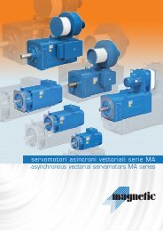
AC SERVO DRIVES<br />
<strong>JUNMA</strong> SERIES<br />
Pulse Reference Type – Mechatrolink-II Network Type<br />
EN<br />
DE<br />
ES<br />
FR<br />
IT<br />
<strong>JUNMA</strong><br />
<strong>JUNMA</strong><br />
<strong>JUNMA</strong> <strong>JUNMA</strong><br />
<strong>JUNMA</strong> <strong>JUNMA</strong><br />
<strong>JUNMA</strong> <strong>JUNMA</strong>
New Servo Concept<br />
<strong>JUNMA</strong><br />
Contents<br />
Page 2<br />
About YASKAWA<br />
New Servo Concept <strong>JUNMA</strong><br />
Page 3<br />
<strong>JUNMA</strong> SERVOPACK –<br />
Fast & Easy Setup<br />
About YASKAWA Servos<br />
Page 4/5<br />
Servomotors<br />
Specifications & Dimensions<br />
Page 6/7<br />
Servopacks<br />
Pulse Reference Type<br />
Specifications & Dimensions<br />
<strong>JUNMA</strong> similarly uses the world’s toplevel<br />
servo technology to provide a quick<br />
and efficient setup. <strong>JUNMA</strong> is a modern<br />
concept of digital servo drive technology<br />
that requires no parameter settings and<br />
gain adjustments to achieve high-precision<br />
positioning.<br />
<strong>JUNMA</strong>’s simple Plug’n Play design, easy<br />
set-up procedures and high precision<br />
characteristics offer optimum drive<br />
performance and efficiency for any kind of<br />
application and industry.<br />
The <strong>JUNMA</strong> Mechatrolink-II network type<br />
servo drive can maintain steady operation<br />
YASKAWA <strong>JUNMA</strong> Features<br />
at high speed by automatically adjusting the<br />
speed to compensate load change in real<br />
time. <strong>JUNMA</strong> ML-II easily connects every<br />
servo drive with the other (up to 16 axes)<br />
and enables start-up and control using one<br />
cable.<br />
<strong>JUNMA</strong> occupies 30% less space than<br />
comparable drives in the market and<br />
remarkably reduces start-up and installation<br />
time.<br />
<strong>JUNMA</strong>’s ready-to-use features for highspeed,<br />
high-torque, and high-precision<br />
operation are ready to work for you.<br />
Page 8/9<br />
Servopacks<br />
Mechatrolink-II Network Type<br />
Specifications & Dimensions<br />
Features of <strong>JUNMA</strong> Pulse<br />
Reference Type Drives<br />
Attain optimum servo performance without<br />
setting parameters or adjusting gains<br />
Quick and efficient setup<br />
– connect and go! Same concept as other<br />
<strong>JUNMA</strong> products, hence no troublesome<br />
parameter settings and gain adjustments<br />
needed<br />
Page 10/11<br />
Ordering Instructions<br />
Resolution: 10,000 pulses/rev<br />
High torque output at high speeds of 4,500<br />
min -1 , easily suppress mechanical vibrations<br />
with the turn of the rotary switch<br />
Conforms to international standards<br />
Features of Mechatrolink-II<br />
Communications Type<br />
Automatic speed adjustment when load<br />
changes<br />
– constant automatic adjustment function<br />
quickly reacts to load changes,<br />
– steady operation for applications with high<br />
frequency speed and torque changes<br />
Enhanced control functions<br />
– high-precision and high-performance<br />
positioning. The position reference, speed<br />
reference, and acceleration/deceleration<br />
time can be changed in real time during<br />
positioning.<br />
– external positioning function using position<br />
latch signal: Detects the accurate position<br />
when a latch signal is received and adjusts<br />
the amount of movement. This is useful for<br />
transfer, wrapping, and printing equipment<br />
– zero point return: A zero point can be<br />
individually set for each of customer’s<br />
machines<br />
– other functions: Interpolation, JOG operation,<br />
alarm reset, and other helpful functions<br />
Conforms to international standards<br />
2 YASKAWA <strong>JUNMA</strong>
YASKAWA<br />
YASKAWA<br />
YASKAWA<br />
YASKAWA<br />
About YASKAWA Servos<br />
<strong>JUNMA</strong> SERVOPACK – FAST & EASY SETUP<br />
Settings are easy to make, so setup<br />
time is reduced.<br />
Unpacking<br />
Remove the SERVOPACK<br />
from the box.<br />
Installation and wiring<br />
Connect the cables for the<br />
power supply, signal lines,<br />
and a motor.<br />
Pulse Control Type<br />
Mechatrolink-II Network Type<br />
Reference pulse setting<br />
Select the reference pulse<br />
switch for your controller.<br />
No parameter settings<br />
and gain adjustments<br />
are needed.<br />
Communication settings<br />
Only required for communication<br />
settings. No gain adjustments<br />
are needed.<br />
YASKAWA<br />
Screwdriver<br />
provided<br />
Controller<br />
Setup completion<br />
The motor is ready to run with<br />
the reference from the controller.<br />
The required torque<br />
is possible even at a<br />
high-speed rotation<br />
of 4500 min -1 .<br />
3
Servomotors<br />
Ratings and Specifications<br />
* 1 These items and speed/torque characteristics quoted<br />
in combination with a SJDE Servopack are at an<br />
armature winding temperature of 100 °C. Other values<br />
are at 20 °C.<br />
* 2 The rated torques listed here are the values for<br />
the continuous allowable torque at 40 °C with an<br />
aluminium heatsink (250 mm × 250 mm × 6 mm)<br />
attached.<br />
Voltage<br />
200 VAC<br />
Servomotor Model SJME- A 01 02 04 08<br />
Applicable servopack SJDE- A 01 02 04 08<br />
Rated output * 1 W 100 200 400 750<br />
Rated torque * 1, * 2 Nm 0.318 0.637 1.27 2.39<br />
Instantaneous peak torque * 1 Nm 0.955 1.91 3.82 7.16<br />
Rated current * 1 A rms<br />
0.84 1.1 2.0 3.7<br />
Instantaneous max. current * 1 A rms<br />
2.5 3.3 6.0 11.1<br />
Rated speed * 1 min -1 3000<br />
Max. speed * 1 min -1 4500<br />
Torque constant Nm/A rms<br />
0.413 0.645 0.682 0.699<br />
Rotor moment of inertia kg ×m 2 ×10 -4 0.0634 0.330 0.603 1.50<br />
Rated power rate * 1 kW*/s 16.0 12.3 26.7 38.1<br />
Rated angular<br />
acceleration * 1 rad/s 2 50200 19300 21100 15900<br />
Time rating<br />
Continuous<br />
Thermal class<br />
B<br />
Vibration class<br />
15 μm or below<br />
Withstand voltage<br />
1500 VAC for one minute<br />
Insulation resistance<br />
500 VDC, 10 MΩ min.<br />
Enclosure<br />
Totally enclosed, self-cooled, IP55<br />
(excluding shaft opening and connectors)<br />
Impact acceleration: 490 m/s 2 in three directions – vertical, side to<br />
Impact resistance<br />
side, and front to back.<br />
Impact occurrencies: 2<br />
Vibration resistance<br />
Vibration acceleration: 49 m/s 2 in three directions – vertical, side to<br />
side, and front to back.<br />
Holding Brake Specifications<br />
* To obtain the motor moment of inertia with a brake,<br />
add the holding brake moment of inertia to the rotor<br />
moment of inertia. The rated power rate and angular<br />
acceleration of the motor will change according to the<br />
motor moment of inertia.<br />
Notes: <br />
1 The holding brake is only used to hold the load and<br />
cannot be used to stop the servomotor.<br />
2 Do not use the holding brake when the servo is on.<br />
Failure to observe this caution may result in an overload<br />
of the servopack or a decrease of brake life.<br />
How to read a graph<br />
of speed and torque characteristics<br />
Servomotor Model SJME- A 01 02 04 08<br />
Rated voltage 24 VDC ± 10%<br />
Holding brake moment of inertia * kg ×m 2 ×10 -4 0.0075 0.064 0.171<br />
Capacity W 6 6.9 7.7<br />
Minimum holding torque (Static friction torque) Nm 0.318 1.27 2.39<br />
Coil resistance Ω (at 20 °C) 96 83 75<br />
Rated current A (at 20 °C) 0.25 0.29 0.32<br />
Brake release time ms 80 max.<br />
Rise time for holding torque ms 100 max.<br />
Speed/Torque Characteristics<br />
Speed (min -1 )<br />
Torque (Nm)<br />
A. Continuous operating range<br />
Safe range allowing the<br />
continuous operation of the<br />
servomotor. The effective<br />
torque must be within this<br />
range.<br />
The output torque<br />
will decrease if the<br />
speed exceeds the<br />
rated speed.<br />
Rated operating<br />
point<br />
Rated torque<br />
The same torque<br />
is output at any<br />
rotating speed.<br />
B. Repetitive operating range<br />
Range where the motor<br />
can be operated for a short<br />
time, provided that the<br />
effective torque of the<br />
motor is within the continuous<br />
operating range.<br />
Speed (min -1 )<br />
Speed (min -1 )<br />
Speed (min -1 )<br />
Speed (min -1 )<br />
Torque (Nm)<br />
Torque (Nm) Torque (Nm) Torque (Nm)<br />
Note: Solid lines show the torque/speed characteristics of the servomotor at 200 VAC, and the broken lines show them at 230 VAC.<br />
4 YASKAWA <strong>JUNMA</strong>
Dimensions<br />
100 W<br />
Encoder cable<br />
Type<br />
SJME-<br />
200 W to 750 W<br />
L LL Approx. mass<br />
(kg)<br />
01AMC41 119 94 0.5<br />
01AMC4C 164 139 0.8<br />
Encoder cable<br />
Servomotor main<br />
circuit cable<br />
Holding brake (de-energization operation)<br />
Power supply: 24 VDC<br />
Note: Only for servomotors with brakes<br />
Holding brake torque = Motor rated torque<br />
Servomotor main<br />
circuit cable<br />
Encoder connector<br />
Motor connector<br />
Cross Section A-A<br />
Encoder connector<br />
Motor connector<br />
Motor Connector Specifications<br />
Extension: BKUA854NN0085155A000<br />
Motor Connector Specifications<br />
Units: mm<br />
Extension: BKUA854NN0085155A000<br />
Motor Connector 1 Male Specifications<br />
Contact No brake (Crimp): 61.006.11 With brake<br />
Motor Connector<br />
1 Male Contact (Crimp): 61.006.11<br />
5 Specifications<br />
5<br />
(INTERCONTEC) (INTERCONTEC)<br />
Pin Description Colour Description Colour<br />
Extension: BKUA854NN0085155A000<br />
1 Phase U Red Phase U Red<br />
4 1 Male 4 2 Contact Plug: BSTA852NN0085201A000<br />
(Crimp): 12<br />
Male Plug: 61.006.11 Contact BSTA852NN0085201A000<br />
(Crimp): 61.006.11<br />
5 6<br />
(INTERCONTEC)<br />
3<br />
56<br />
Female 3 Contact 2(Crimp): Phase 60.001.11 V White Phase V White<br />
(INTERCONTEC)<br />
Female Contact (Crimp): 60.001.11<br />
4<br />
2 Plug: BSTA852NN0085201A000 3(Solder): Phase 60.004.11 W Blue Phase W Blue<br />
6<br />
3<br />
Female 4 Contact 2(Crimp): Plug: 60.001.11 BSTA852NN0085201A000<br />
(Solder): 60.004.11<br />
Green/<br />
6<br />
3 (Solder): 4 60.004.11 FG<br />
Female Contact Yellow (Crimp): FG Green/<br />
60.001.11 Yellow<br />
Phase U Red Phase U Red 5 – (Solder): – Brake60.004.11<br />
Red<br />
Phase V White Phase V White<br />
Phase W Blue Phase W Blue<br />
6 – – Brake Black<br />
Phase U Red<br />
FG Green/Yellow Phase Phase U U<br />
FG Red<br />
Green/Yellow Phase U Red<br />
Phase V White Phase V White<br />
Phase W Blue Phase Phase V WBrake<br />
White Blue Red Phase V White<br />
FG Green/Yellow FG Brake Green/Yellow Extension: Black BKUA854NN0085155A000<br />
Phase W Blue Phase W Blue<br />
Brake Red Male contact (Crimp): 61.006.11 (Intercontec)<br />
Phase FG<br />
Brake U Green/Yellow Red FG<br />
Encoder Connector Specifications Black Plug: BSTA852NN0085201A000<br />
Phase U Green/Yellow<br />
Red<br />
Phase V White Female Contact: Brake Phase (Crimp): V 60.001.11 Red White<br />
Encoder Extension: AKUA047NN0084151A000<br />
9Connector 1 Specifications Phase W Blue Brake Phase (Solder): W Black 60.004.11 Blue<br />
8<br />
10<br />
Male Contact (Crimp): 61.004.11<br />
Extension: AKUA047NN0084151A000<br />
9 12<br />
1<br />
FG<br />
2<br />
Male Contact (INTERCONTEC)<br />
Green/Yellow FG Green/Yellow<br />
8<br />
10<br />
(Crimp): 61.004.11<br />
7 Encoder 3<br />
12<br />
2 (INTERCONTEC) Connector Specifications Brake Red<br />
Plug: ASTA046NN0084200A000<br />
6<br />
11<br />
7<br />
3<br />
Brake Black<br />
5 Plug: 4 ASTA046NN0084200A000<br />
Female Contact Extension: (Crimp): 60.001.11 AKUA047NN0084151A000<br />
6<br />
11 9<br />
1<br />
5<br />
4 Female Contact (Crimp):<br />
Male (Solder): 60.001.11<br />
Contact 60.004.11<br />
Encoder 8<br />
10<br />
(Crimp): 61.004.11<br />
Connector (Solder): Connector 60.004.11 Specifications Specifications<br />
12<br />
2 (INTERCONTEC)<br />
PG5 V Red<br />
7<br />
3 Extension: AKUA047NN0084151A000<br />
PG5 VPG0 V(GND) Red 9 Black 1<br />
Plug: PinASTA046NN0084200A000<br />
Description Colour<br />
PG0 V(GND) Phase A+ 6Black<br />
8 Blue 10<br />
11 Male Contact (Crimp): 61.004.11<br />
Phase Phase A+ A-Blue<br />
5 Blue / White 42<br />
Female (INTERCONTEC) 1Contact PG5 (Crimp): V 60.001.11 Red<br />
12<br />
Phase -A-<br />
Blue / White -<br />
-<br />
Phase B+ 7-<br />
(Solder): 60.004.11<br />
Yellow<br />
3<br />
PG0 V<br />
Phase<br />
Phase<br />
B+<br />
B-<br />
Yellow<br />
Plug: ASTA046NN0084200A000<br />
2<br />
Black<br />
6 Yellow / White 11<br />
(GND)<br />
Phase B- Yellow / White<br />
Phase /Z Purple<br />
Phase /Z Purple 5<br />
4 Female Contact (Crimp): 60.001.11<br />
Phase<br />
Phase<br />
U<br />
U<br />
GrayPG5 Gray V Red 3 Phase A+ Blue<br />
Phase Phase V V Green Green<br />
(Solder): 60.004.11<br />
Phase Phase W W PG0<br />
Orange Orange V(GND) Black 4 Phase A– Blue/White<br />
- - - Phase - A+ Blue<br />
Case Frame Case Frame Ground Ground Shield Phase Wire Shield A- Wire<br />
5 – –<br />
PG5 V Blue Red/ White<br />
-PG0 V(GND) -Black<br />
6 Phase B+ Yellow<br />
Phase B+ A+ Yellow Blue<br />
Yellow/<br />
Phase B- A- Yellow Blue // White White 7 Phase B–<br />
White<br />
Phase - /Z Purple -<br />
Phase Phase UB+<br />
Gray 8 Phase /Z Purple<br />
Yellow<br />
Phase VB-<br />
Green Yellow / 9White<br />
Phase U Gray<br />
Phase W/Z<br />
Orange Purple10 Phase V Green<br />
-Phase U -Gray<br />
Cross Section A-A Case Frame Phase Ground V Shield GreenWire<br />
11 Phase W Orange<br />
Phase W Orange12 – –<br />
-<br />
-<br />
Frame<br />
Case Frame Ground Shield CaseWire<br />
Shield wire<br />
ground<br />
Extension: BKUA854NN0085155A000<br />
Extension: AKUA047NN0084151A000<br />
Male contact (Crimp): 61.004.11 (Intercontec)<br />
Plug: ASTA046NN0084200A000<br />
Female Contact: (Crimp): 60.001.11<br />
(Solder): 60.004.11<br />
Holding brake (de-energization operation)<br />
Power supply: 24 VDC<br />
Note: Only for servomotors with brakes<br />
Holding brake torque = Motor rated torque<br />
Type SJME- L LL LR LG LE S LB LC LD LF LA LZ QK Approx. mass<br />
(kg)<br />
02AMC41 125.5 95.5<br />
0.9<br />
– –<br />
02AMC4C 165.5 135.5 1.5<br />
30 6 3 14 0 50 0 60<br />
70 5.5 20<br />
-0.011 -0.039<br />
04AMC41 148.5 118.5<br />
1.3<br />
– –<br />
04AMC4C 188.5 158.5 1.9<br />
08AMC41 173 133<br />
2.6<br />
40 8 3 16 0 70 0 80 35 20 90 7 30<br />
-0.011 -0.046<br />
08AMC4C 216 176 3.5<br />
5
Servopacks – Pulse Reference Type<br />
Ratings and Specifications<br />
* 1 Be sure to use the motor within the allowable load<br />
moment of inertia. The motor will become unstable<br />
if the load moment of inertia exceeds the allowable<br />
value.<br />
* 2 The ground protection circuit is designed for ground<br />
fault inside the motor windings while the motor is<br />
running. Therefore, it may not protect the system<br />
under the following cases:<br />
• A low-resistance ground fault occurs in the main<br />
circuit cable or in the connector of the cable for the<br />
servomotor.<br />
• The power supply is turned on during a ground fault.<br />
SERVOPACK Model SJDE- 01APA 02APA 04APA 08APA<br />
Max. applicable servomotor capacity kW 0.1 0.2 0.4 0.75<br />
Continuous output current A rms<br />
0.84 1.1 2.0 3.7<br />
Instantaneous max. output current A rms<br />
2.5 3.3 6.0 11.1<br />
Input power supply<br />
(for main circuit<br />
and control circuit)<br />
Voltage Single-phase 200 to 230 VAC, +10 to −15%<br />
Frequency 50/60 Hz ± 5%<br />
Voltage frequency capacity<br />
at rated output kVA<br />
0.40 0.75 1.2 2.2<br />
Power loss at rated output W 14 16 24 35<br />
Input control method<br />
Capacitor-input type, single-phase full-wave rectification with<br />
resistance to prevent inrush currents<br />
Output control method<br />
PWM control, sine wave power driven system<br />
Feedback<br />
Incremental encoder<br />
Allowable load inertia* 1 kgm 2 0.6 ×10 -4 3 ×10 -4 5 ×10 -4 10 ×10 -4<br />
I/O signals<br />
Built-in functions<br />
Input signal<br />
for reference<br />
(designated pulse<br />
type and pulse<br />
resolution with<br />
pulse switch)<br />
Clear input signal<br />
Servo on input signal<br />
Alarm output signal<br />
Brake output signal<br />
Pulse type<br />
Pulse resolution<br />
Position completed output signal<br />
Origin output signal<br />
Dynamic brake (DB)<br />
Regenerative processing<br />
Protection * 2<br />
Display<br />
Reference filter<br />
Cooling method<br />
Select one of the following settings:<br />
1. CCW + CW pulse train<br />
2. Sign + pulse train<br />
3. CCW + CW pulse train (negative logic)<br />
4. Sign + pulse train (negative logic)<br />
Select one of the following settings:<br />
1. 1000 pulses/rev (open collector/line driver) 75 kpps max.<br />
2. 2500 pulses/rev (open collector/line driver) 187,5 kpps max.<br />
3. 5000 pulses/rev (line driver) 375 kpps max.<br />
4. 10000 pulses/rev (line driver) 750 kpps max.<br />
Clears the positioning error at the rising edge of the pulse<br />
Turns the servomotor on or off<br />
Off if an alarm occurs<br />
External signal to control brakes.<br />
Turn ON to release the brake.<br />
On if the current position is equal to the reference position<br />
± 10 pulses<br />
On if the motor is at the origin (width: 1/500 rev)<br />
Operated at main power off, servo alarm, servo off<br />
(off after motor stops; on if the motor power is off)<br />
Optional (if the regenerative energy is too large,<br />
install a regenerative unit)<br />
Speed errors, overload, encoder errors, voltage errors, over currents,<br />
disablement of the built-in cooling fan, system errors<br />
Five LED indicators (PWR, Ref, Al1, AL2, Al3)<br />
Select one of eight levels with Fil switch<br />
Forced cooling (built-in fan)<br />
Operating temperature 0 °C to +55 °C<br />
Operating humidity<br />
90% RH or less (no condensation)<br />
Storage temperature –20 °C to +70 °C<br />
Storage humidity<br />
90% RH or less (no condensation)<br />
Free of corrosive gases<br />
Installation site<br />
Free of dust and iron powder<br />
Clean and dry<br />
Altitude<br />
1000 m or below<br />
Vibration resistance 4.9 m/s 2<br />
Shock resistance 19.6 m/s 2<br />
Operating conditions<br />
Installation category (overvoltage category): II<br />
Pollution degree: 2<br />
Protection class: IP1X (EN50178)<br />
6 YASKAWA <strong>JUNMA</strong>
Dimensions<br />
SJDE-01, 02 (100 W, 200 W)<br />
Units: mm<br />
Mounting Hole Diagram<br />
4.5 dia. holes<br />
2-M4 mounting holes<br />
Airflow<br />
Cooling fan<br />
(Mounting pitch)<br />
Nameplate<br />
Airflow<br />
Ground terminal<br />
with 2xM4 screws<br />
SJDE-04 (400 W)<br />
4.5 dia. holes<br />
Airflow<br />
Mounting Hole Diagram<br />
2-M4 mounting holes<br />
Visible outline<br />
(Mounting pitch)<br />
Cooling fan<br />
Nameplate<br />
Airflow<br />
Ground terminal<br />
with 2xM4 screws<br />
SJDE-08 (750 W)<br />
4.5 dia. holes<br />
Airflow<br />
Mounting Hole Diagram<br />
2-M4 mounting holes<br />
Visible outline<br />
Cooling fan<br />
(Mounting pitch)<br />
Nameplate<br />
Airflow<br />
Ground terminal<br />
with 2xM4 screws<br />
7
Servopacks – Mechatrolink-II Network Type<br />
Ratings and Specifications<br />
* 1 Be sure to use the motor within the allowable load<br />
moment of inertia. The motor will become unstable<br />
if the load moment of inertia exceeds the allowable<br />
value.<br />
* 2 The ground protection circuit is designed for ground<br />
fault inside the motor windings while the motor is<br />
running. Therefore, it may not protect the system<br />
under the following cases:<br />
• A low-resistance ground fault occurs in the main<br />
circuit cable or in the connector of the cable for the<br />
servomotor.<br />
• The power supply is turned on during a ground fault.<br />
SERVOPACK Model SJDE- 01ANA 02ANA 04ANA 08ANA<br />
Applicable servomotor capacity kW 0.1 0.2 0.4 0.75<br />
Continuous output current A rms<br />
0.84 1.1 2 3.7<br />
Instantaneous max. output current A rms<br />
2.5 3.3 6 11.1<br />
Basic specifications<br />
Built-in functions<br />
Input power<br />
supply<br />
(for main circuit<br />
and control<br />
circuit)<br />
Voltage Single-phase 200 to 230 VAC, +10 to −15%<br />
Frequency 50/60 Hz ± 5%<br />
Voltage frequency<br />
capacity<br />
at rated output<br />
0.40 0.75 1.2 2.2<br />
kVA<br />
Power loss at rated output W 14 16 24 35<br />
Input control method<br />
Output control method<br />
Capacitor-input type, single-phase full-wave rectification with resistance to<br />
prevent inrush currents<br />
PWM control, sine wave power driven system<br />
Allowable load moment of inertia* 1 kgm 2 0.5 ×10 -4 3 ×10 -4 5 ×10 -4 10 ×10 -4<br />
Leakage current<br />
3.5 mA max.<br />
Dynamic brake (DB)<br />
Activated when the power is off, a servo is off, or an alarm occurs<br />
(Released after the motor stops, applied if the power supply is turned off)<br />
Communications for maintenance JunmaWin (Modification/initialization of parameters, JOG operation, etc)<br />
Regenerative processing<br />
If the regenerative energy is too large, mount a regenerative unit<br />
Emergency stop<br />
Emergency Stop (E-STP)<br />
Overtravel (OT) prevention<br />
Forward run prohibited (P-OT), reverse run prohibited (N-OT)<br />
Display<br />
Four LED indicators (PWR, RDY, COM, ALM)<br />
Monitor<br />
Power supply status monitor, servo ON/OFF monitor, MECHATROLINK monitor<br />
Feedback<br />
Incremental encoder (8192 pulses/rev)<br />
Reference resolution setting (electronic<br />
gear)<br />
0.01 ≤ B/A ≤ 100<br />
Protection<br />
Speed error, overload, encoder error, voltage error, overcurrent,<br />
built-in cooling fan stop, system error, ground fault * 2<br />
MECHATROLINK<br />
communications<br />
Command method<br />
Communications<br />
protocol<br />
Station address<br />
Transmission speed<br />
Transmission cycle<br />
Data length<br />
Performance<br />
Sequence input<br />
Fixed inputs<br />
signals<br />
Sequence output<br />
Fixed outputs<br />
signals<br />
Operating temperature / operating humidity<br />
Storage temperature / storage humidity<br />
MECHATROLINK-II<br />
41H to 5FH<br />
10 Mbps<br />
1 ms, 1.5 ms, 2 ms, 3 ms, 4 ms<br />
17 bytes or 32 bytes<br />
MECHATROLINK-II communications<br />
MECHATROLINK-II commands (for motion, data setting/reference, monitor,<br />
adjustment, and other commands)<br />
5 inputs (external latch signal, homing deceleration signal, forward run<br />
prohibited signal, reverse run prohibited signal, and emergency stop signal)<br />
2 outputs (servo alarm and holding brake)<br />
0°C to +55°C /90% RH or less (no condensation)<br />
-20°C to +70°C /90% RH or less (no condensation)<br />
Free from corrosive gases, free from dust and iron particles, free from water<br />
Ambient conditions<br />
droplets or machine oil<br />
Altitude<br />
1000 m or below<br />
Vibration resistance / shock resistance 4.9 m/s 2 /19.6 m/s 2<br />
Operating conditions<br />
Installation category (overvoltage category): II, pollution degree: 2,<br />
protection class: IP1X (EN50178)<br />
8 YASKAWA <strong>JUNMA</strong>
SJDE-01, 02 (100 W, 200 W)<br />
Mounting Hole Diagram<br />
Dimensions<br />
Units: mm<br />
2-M4 mounting holes<br />
YASKAWA<br />
(Mounting pitch)<br />
Visible outline<br />
Ground terminal<br />
with 2xM4 screws<br />
Nameplate<br />
(Mounting pitch)<br />
SJDE-04 (400 W)<br />
Mounting Hole Diagram<br />
150<br />
YASKAWA<br />
(16)<br />
125˚<br />
(6)<br />
(4.5)<br />
150<br />
139.5 ±0.5 5.5<br />
(Mounting pitch)<br />
2-M4 mounting holes<br />
Visible outline<br />
YASKAWA ELECTRIC<br />
Ground terminal<br />
with 2xM4 screws<br />
45<br />
(5) Nameplate<br />
(75) 130<br />
(5)<br />
5 32±0.5 (8)<br />
45<br />
(Mounting pitch)<br />
SJDE-08 (750 W)<br />
Mounting Hole Diagram<br />
150<br />
Ground terminal<br />
with 2xM4 screws<br />
YASKAWA<br />
70<br />
(16)<br />
125˚<br />
(6)<br />
YASKAWA ELECTRIC<br />
(5)<br />
Nameplate Cooling fan<br />
(75)<br />
180<br />
(4)<br />
150<br />
(5) 139.5 ±0.5<br />
5.5<br />
(Mounting pitch)<br />
6 58±0.5 (6)<br />
70<br />
(Mounting pitch)<br />
3-M4 mounting holes<br />
Visible outline<br />
9
C<br />
DEF<br />
DEF<br />
0<br />
1 2 3 4 56 7<br />
C<br />
0<br />
1 2 3 4 56 7<br />
Ordering Instructions<br />
Servo Motor Model Designation<br />
SJME - 02 A M C 4 1 - OY<br />
Junma Servomotor<br />
Junma Servo Motor<br />
3,000 rpm<br />
(100 –750 W)<br />
Capacity<br />
Output (W) Code<br />
100 01<br />
200 02<br />
400 04<br />
750 08<br />
Brake Specifications<br />
Specification Code<br />
No Brake 1<br />
24 VDC Brake C<br />
Shaft end Specifications<br />
Specification Code<br />
Straight with key 4<br />
Voltage<br />
Specification Code<br />
200 VAC A<br />
Design procedure<br />
Specification Code<br />
Standard<br />
C<br />
Feedback specification<br />
Specification<br />
Code<br />
Analogue output encoder M<br />
Servopack Model Designation<br />
Junma<br />
Mechatrolink-II<br />
Servo Drive<br />
YASKAWA<br />
Junma Pulse<br />
Servo Drive<br />
YASKAWA<br />
200V<br />
SJDE- 02 APA-OY<br />
REF<br />
PULSE<br />
AL1<br />
AL2<br />
AL3<br />
FIL<br />
C<br />
N<br />
1<br />
C<br />
N<br />
2<br />
PWR<br />
89AB<br />
89AB<br />
L1<br />
L2<br />
+<br />
-<br />
CNA CNB<br />
U<br />
V<br />
W<br />
Junma Series<br />
SJDE Servopack<br />
Applicable Servomotor Capacity<br />
Output (W)<br />
Code<br />
100 01<br />
200 02<br />
400 04<br />
750 08<br />
SJDE - 02 A P A - OY<br />
Design Revision Order<br />
A, B…<br />
Interface Specification<br />
Specification<br />
Pulse Reference Control<br />
Mechatrolink-II<br />
Power Supply Voltage<br />
Specification<br />
Code<br />
200 VAC A<br />
Code<br />
P<br />
N<br />
10 YASKAWA <strong>JUNMA</strong>
Ordering Instructions<br />
Power Cables<br />
Specifications Model Appearance<br />
Power cable for Junma<br />
servomotors<br />
without brake<br />
Power cable for Junma<br />
servomotors<br />
with brake<br />
Encoder Cables<br />
Flexible cables (Standard)<br />
Shielded Cable<br />
Bending radius (Dynamic) > 10 x Diameter<br />
Bending cycles >5 Million<br />
Flexible cables (Standard)<br />
Shielded Cable<br />
Bending radius (Dynamic) > 10 x Diameter<br />
Bending cycles >5 Million<br />
Connectors for power and encoder<br />
1.5 m JZSP-CHM000-01-5-E-G4<br />
3 m JZSP-CHM000-03-E-G4<br />
5 m JZSP-CHM000-05-E-G4<br />
10 m JZSP-CHM000-10-E-G4<br />
15 m JZSP-CHM000-15-E-G4<br />
20 m JZSP-CHM000-20-E-G4<br />
1.5 m JZSP-CHM030-01-5-E-G4<br />
3 m JZSP-CHM030-03-E-G4<br />
5 m JZSP-CHM030-05-E-G4<br />
10 m JZSP-CHM030-10-E-G4<br />
15 m JZSP-CHM030-15-E-G4<br />
20 m JZSP-CHM030-20-E-G4<br />
Specifications Model Appearance<br />
Encoder cable for<br />
Junma<br />
servomotors<br />
Flexible cables (Standard)<br />
Shielded Cable<br />
Bending radius (Dynamic) > 10 x Diameter<br />
Bending cycles >5 Million<br />
1.5 m JZSP-CHP800-01-5-E-G4<br />
3 m JZSP-CHP800-03-E-G4<br />
5 m JZSP-CHP800-05-E-G4<br />
10 m JZSP-CHP800-10-E-G4<br />
15 m JZSP-CHP800-15-E-G4<br />
20 m JZSP-CHP800-20-E-G4<br />
Specifications Model (Yaskawa) Model (Manufacturer)<br />
Connectors for making power cables<br />
Drive side (CNB) Manufacturer: JST JZSP-CHM9-2 04JFAT-SAYGF-N<br />
Motor side Manufacturer: Intercontec BSTA852NN0085201A000 *<br />
Connectors for making encoder cables<br />
Drive side (CN2) Manufacturer: 3M JZSP-CHP9-2 Shell kit: 36310-3200-008 **<br />
Motor side Manufacturer: Intercontec ASTA046NN0084200A000 *<br />
Connector Kit for Power Supply / Regenerative Unit Drive side (CNA) Manufacturer: JST JZSP-CHG9-1 04JFAT-SBXGF-N<br />
* Note: Female contacts for Intercontec plugs have to be ordered separately, Crimp Type: 60.001.11 - Solder Type: 60.004.11<br />
Signal and communication cables<br />
Name Type Model Length Appearance<br />
JZSP-CHI003-01<br />
1 m<br />
I/O Signal Cables<br />
JZSP-CHI003-02<br />
2 m<br />
JZSP-CHI003-03<br />
3 m<br />
I/O Signal Connector Kits<br />
MECHATROLINK-II<br />
Communication Cable<br />
For SERVOPACK<br />
CN1<br />
Cable with Connectors<br />
at Both Ends * 1<br />
(Without Ferrite Core)<br />
Cable with Connectors<br />
at Both Ends * 1<br />
(With Ferrite Core)<br />
Terminators<br />
Soldered<br />
Type<br />
JZSP-CHI9-1 –<br />
JEPMC-W6002- * 2 –<br />
JEPMC-W6002- * 2 -E<br />
(Compliant with RoHS Directive)<br />
JEPMC-W6003- * 2 –<br />
JEPMC-W6003- * 2 -E<br />
(Compliant with RoHS Directive)<br />
JEPMC-W6022- * 2 –<br />
JEPMC-W6022- * 2 -E<br />
(Compliant with RoHS Directive)<br />
Cable for Personal Computer Cables JZSP-CPS00-02 2 m<br />
–<br />
–<br />
–<br />
** Note: Part No. of receptacle: 36210-0100FD<br />
PC Communication Board (for Pulse Reference Type only) JUSP-JC001 –<br />
* 1: The total cable length must be 50 m max. and the cable length between stations 0.5 m min.<br />
*2: Specify the cable length in when ordering as shown in the table below.<br />
Cable length m Cable length m Cable length m Cable length m Cable length m<br />
A5 0.5 03 3.0 07 7.0 20 20 40 40<br />
01 1.0 05 5.0 10 10 30 30 50 50<br />
11
Noise Filters<br />
PE Bolt M4x15<br />
PE Bolt M4x15<br />
100 to 400 W SERVOPACKs 750 W SERVOPACKs<br />
Ordering Instructions<br />
Pulse Reference Type<br />
Noise Filter Model<br />
Servopack Model<br />
FB-SJDE04P SJDE-01APA SJDE-02APA SJDE-04APA<br />
FB-SJDE08P<br />
SJDE-08APA<br />
Mechatrolink-II Network Type<br />
Noise Filter Model<br />
Servopack Model<br />
FB-SJDE04N SJDE-01ANA SJDE-02ANA SJDE-04ANA<br />
FB-SJDE08N<br />
SJDE-08ANA<br />
Ratings and Specifications<br />
Noise Filter Model FB- SJDE04P SJDE08P SJDE04N SJDE08N<br />
No. of phase 1<br />
Rated voltage v 250<br />
Rated frequency Hz 50-60<br />
Rated current A 5 9 5 9<br />
Max. leakage current mA 1.7<br />
High voltage test v 2150 (Line-Line) 2700 (Line-Case)<br />
Operating conditions<br />
Protection index IP 20<br />
Ambient temperature °C +45°C<br />
Climatic category<br />
(according to EN 60068-1)<br />
25/085/21<br />
Type of cooling<br />
AN (natural-air cooling)<br />
Air speed m/s -<br />
Operation mode<br />
S1 (continuous operation)<br />
Note: The noise filters are designed as side-by-side-mounted and footprint filters.<br />
12 YASKAWA <strong>JUNMA</strong>
Dimensions<br />
Units: mm<br />
FB-SJDE 04P (SJDE-APA 100 to 400 W)<br />
FB-SJDE08P (SJDE-APA 750 W)<br />
Blind Fastener M4 (2x)<br />
Blind Fastener M4 (2x)<br />
FB-SJDE04N (SJDE-ANA 100 to 400 W) FB-SJDE08N (SJDE-ANA 750 W)<br />
Blind Fastener M4 (2x)<br />
Blind Fastener M4 (3x)<br />
Ratings and Specifications<br />
AC Reactor<br />
Model Inductance (mH) Rated Current (A) Contact<br />
X5052 45.0 1.0<br />
X5053 20.0 2.0<br />
X5054 5.0 3.0<br />
Yaskawa Local Office<br />
X5056 2.0 5.0<br />
Dimensions<br />
I dia.<br />
C<br />
D<br />
G<br />
Model Dimensions (mm) Approx. Mass (kg)<br />
A B C D E F G H I<br />
X5052 35 52 80 95 30 40 45 4 4.3 0.4<br />
X5053 35 52 90 105 35 45 50 4 4.3 0.6<br />
X5054 35 52 80 95 30 40 45 4 4.5 0.4<br />
X5056 35 52 80 95 30 40 45 4 4.3 0.4<br />
Nameplate<br />
4 x H dia.<br />
Notch<br />
A<br />
B<br />
E<br />
F<br />
13
Connection Diagram<br />
Pulse Reference Type<br />
L1<br />
L2<br />
Power supply<br />
Single-phase 200 V to 230 VAC<br />
50/60Hz<br />
Molded-case circuit breaker<br />
Surge absorber<br />
Noise<br />
filter<br />
SW1<br />
SW2<br />
MC1<br />
MC1<br />
MC1<br />
Surge<br />
absorber<br />
Reactor<br />
Fuse<br />
Fuse<br />
L1<br />
L2<br />
AVR1*<br />
24 VDC power supply<br />
+24 V<br />
200 V to<br />
230 VAC<br />
0 V<br />
CNA<br />
1<br />
2<br />
SERVOPACK<br />
Ry1<br />
CNB<br />
1<br />
2<br />
Varistor<br />
U<br />
V<br />
5<br />
6<br />
1<br />
2<br />
V<br />
U<br />
Holding<br />
brake<br />
Servomotor<br />
C1 C2 +<br />
+<br />
3<br />
3<br />
W<br />
3<br />
W FG<br />
AVR2*<br />
24 VDC power<br />
supply<br />
200 V to<br />
230 VAC<br />
+24 V<br />
0 V<br />
Regenerative unit<br />
JUSP-RG08D<br />
—<br />
Y4<br />
Y5<br />
—<br />
4<br />
4<br />
Maintenance<br />
Communication<br />
ports<br />
/TXD<br />
/RXD<br />
GND<br />
Communication<br />
board<br />
JUSP-JC001<br />
CN52<br />
Host Controller<br />
CW,PULS<br />
1<br />
75<br />
CN2<br />
1<br />
PG5V<br />
1<br />
/CW,/PULS<br />
2<br />
75<br />
2<br />
PG0V<br />
2<br />
CCW,SIGN<br />
3<br />
75<br />
3<br />
A+<br />
3<br />
/CCW,/SIGN<br />
4<br />
75<br />
4<br />
A—<br />
4<br />
Notes: 1 AVR1 : 24 VDC power supply for holding brake<br />
AVR2 : 24 VDC power supply for I/O signals<br />
SW1 : Power off switch<br />
SW2 : Power on switch<br />
MC1 : Magnetic contactor<br />
Ry1 : Relay for holding brake<br />
2 The ground fault protection circuit is designed<br />
for ground fault inside the motor windings<br />
while the motor is running.<br />
Therefore, it may not protect the system<br />
under the following cases.<br />
• A low-resistance ground fault occurs in the<br />
main circuit cable or in the connector of the<br />
cable for the servomotor.<br />
• The power supply is turned on during a<br />
ground fault.<br />
To make your system even safer, install a<br />
ground fault interrupter for overloads and<br />
shortcircuits, or install a molded-case<br />
circuit breaker combined with a ground<br />
fault interrupter for ground faults.<br />
2.2 kΩ<br />
Ry1<br />
Flywheel diode<br />
Shield<br />
Manufacturers of Components<br />
CLR<br />
/CLR<br />
PCO<br />
SG-PCO<br />
+24VIN<br />
/S-ON<br />
ALM<br />
/BK<br />
/COIN<br />
SG-COM<br />
8 75<br />
9 75<br />
10<br />
11<br />
5<br />
6<br />
3.4 kΩ<br />
12<br />
13<br />
14<br />
7<br />
Shell<br />
Component Manufacturer Model<br />
Surge absorber Okaya Electric Industries Co., Ltd. (Spark killer) CRE-50500<br />
Flywheel diode Toshiba Corp. 1NH42<br />
Relay for holding brake Omron Corp. MY series<br />
Varistor Nippon Chemi-Con Corp. TNR7V121K<br />
5<br />
6<br />
7<br />
8<br />
9<br />
10<br />
Shell<br />
B+<br />
B—<br />
/Z<br />
U<br />
V<br />
W<br />
Shield<br />
5<br />
6<br />
7<br />
8<br />
9<br />
10<br />
12<br />
Encoder<br />
*: Prepare separate 24 VDC power<br />
supplies for a holding brake and<br />
I/O signals.<br />
14 YASKAWA <strong>JUNMA</strong>
Connection Diagram<br />
L1<br />
L2<br />
Power supply<br />
Single-phase 200 V to 230 VAC<br />
50/60Hz<br />
Molded-case circuit breaker<br />
Surge absorber<br />
Mechatrolink-II Network Type<br />
Noise<br />
filter<br />
MC1<br />
AVR1*<br />
24 VDC<br />
power supply<br />
+24 V<br />
200 V to<br />
230 VAC 0 V<br />
Relay for holding brake<br />
Ry1<br />
Varistor<br />
5<br />
6<br />
Holding<br />
brake<br />
SW1<br />
SW2<br />
MC1<br />
MC1<br />
Surge<br />
absorber<br />
Reactor<br />
Fuse L1<br />
Fuse L2<br />
CNA<br />
1<br />
2<br />
SERVOPACK<br />
CNB<br />
1<br />
2<br />
U<br />
V<br />
1<br />
2<br />
V<br />
U<br />
Servomotor<br />
AVR2*<br />
24 VDC power<br />
supply<br />
200 V to<br />
230 VAC<br />
+24 V 0 V<br />
C1<br />
C2<br />
Regenerative unit<br />
JUSP-RG08D<br />
+<br />
−<br />
Y4<br />
Y5<br />
+<br />
−<br />
3<br />
4<br />
3<br />
W<br />
3<br />
4<br />
W FG<br />
Maintenance<br />
communication<br />
ports<br />
/TXD<br />
/RXD<br />
GND<br />
CN9<br />
1<br />
2<br />
3, 4<br />
CN2<br />
1<br />
2<br />
PG5 V<br />
PG0 V<br />
1<br />
2<br />
Host Controller<br />
MECHATROLINK-II<br />
cable<br />
Shield<br />
S<br />
/S<br />
Terminator<br />
130 Ω<br />
CN6A<br />
A2<br />
A3<br />
Shell<br />
CN6B<br />
B2<br />
B3<br />
3<br />
4<br />
5<br />
6<br />
7<br />
A+<br />
A−<br />
B+<br />
B−<br />
/Z<br />
3<br />
4<br />
5<br />
6<br />
7<br />
Encoder<br />
MC1<br />
24VIN<br />
/EXT1<br />
/DEC<br />
N-OT<br />
P-OT<br />
E-STP<br />
ALM<br />
CN1<br />
5<br />
1<br />
3.3 kΩ<br />
2<br />
3.3 kΩ<br />
3<br />
3.3 kΩ<br />
4<br />
3.3 kΩ<br />
6<br />
3.3 kΩ<br />
12<br />
8<br />
9<br />
10<br />
Shell<br />
U<br />
V<br />
W<br />
Shield<br />
8<br />
9<br />
10<br />
12<br />
Ry1<br />
/BK<br />
13<br />
Flywheel diode<br />
Shield<br />
SG-COM<br />
7<br />
Shell<br />
*: Prepare separate 24 VDC<br />
power supplies for a holding<br />
brake and I/O signals.<br />
AVR1<br />
AVR2<br />
24 VDC power supply for<br />
a holding brake<br />
24 VDC power supply for<br />
I/O signals<br />
SW1<br />
SW2<br />
MC1<br />
Ry1<br />
Emergency Stop Switch<br />
Power on switch<br />
Magnetic contactor<br />
Relay for holding brake<br />
15
YASKAWA Europe GmbH<br />
Drives & Motion Division<br />
Hauptstr. 185<br />
65760 Eschborn<br />
Germany<br />
+49 6196 569-300<br />
info@yaskawa.eu.com<br />
www.yaskawa.eu.com<br />
Specifications are subject to change without notice<br />
for ongoing product modifications and improvements.<br />
© YASKAWA Europe GmbH. All rights reserved.<br />
Literature No. YEU_MuC_<strong>JUNMA</strong>_EN_v4_1110<br />
Printed in Germany November 2010