4-20 mA Transmitter, Isolated API 4300 PLC, API 4300 D PLC
4-20 mA Transmitter, Isolated API 4300 PLC, API 4300 D PLC
4-20 mA Transmitter, Isolated API 4300 PLC, API 4300 D PLC

You also want an ePaper? Increase the reach of your titles
YUMPU automatically turns print PDFs into web optimized ePapers that Google loves.
4-<strong>20</strong> <strong>mA</strong> <strong>Transmitter</strong>, <strong>Isolated</strong> <strong>API</strong> <strong>4300</strong> <strong>PLC</strong>, <strong>API</strong> <strong>4300</strong> D <strong>PLC</strong><br />
Input:<br />
Output:<br />
4-<strong>20</strong> <strong>mA</strong> DC Sink or Source<br />
4-<strong>20</strong> <strong>mA</strong> DC Sink or Source<br />
Input and Output Configurable for Sink or Source<br />
Built-In Loop Power Supplies for Input and Output<br />
Full <strong>20</strong>00 V Input/Output/Power Isolation<br />
Input and Output LoopTracker ® LEDs<br />
Local or Remote Functional Output Test<br />
Applications<br />
Isolate Single-Ended Inputs, Eliminate <strong>PLC</strong>/DCS Ground Loops<br />
Isolate and Correct Sink-Sink or Source-Source Mismatches<br />
Use with Allen Bradley, GE/Fanuc, IDEC, Omron, Mistubishi,<br />
Modicon, Siemens, Panasonic, Honeywell Analog Inputs<br />
Solve isolation and ground loop problems when using <strong>PLC</strong>s that have single-ended<br />
(common ground ) 4-<strong>20</strong> <strong>mA</strong> inputs. This often results in erroneous and unpredictable<br />
input signals to the <strong>PLC</strong> due to varying ground potentials in the system. Full<br />
3-way (power/input/output) isolation can eliminate ground loop problems and restore<br />
proper <strong>PLC</strong> function. Use with either passive or powered 4-<strong>20</strong> <strong>mA</strong> signal sources and<br />
be connected to <strong>PLC</strong> 4-<strong>20</strong> <strong>mA</strong> inputs that are either powered or passive.<br />
Specifications<br />
Input Range<br />
4-<strong>20</strong> <strong>mA</strong> DC<br />
Configurable for sinking (unpowered) or sourcing (powered) input depending on<br />
input terminal connections<br />
Maximum range approximately 3 <strong>mA</strong> to 23 <strong>mA</strong><br />
Input Voltage Burden<br />
1.25 VDC maximum<br />
Input Impedance<br />
50 Ω typical<br />
Output Zero and Span<br />
Multi-turn potentiometers to compensate for load and lead variations<br />
±15% of span adjustment range typical<br />
Input Loop Power Supply<br />
15 VDC nominal, regulated, 25 <strong>mA</strong> DC, max. ripple, less than 1.5 V p-p<br />
LoopTracker<br />
Variable brightness LEDs indicate input/output loop level and status<br />
Output Range<br />
4-<strong>20</strong> <strong>mA</strong> DC<br />
<strong>20</strong> V compliance, 1000 Ω at <strong>20</strong> <strong>mA</strong><br />
Configurable for sinking (unpowered) or sourcing (powered) output depending on<br />
output terminal connections<br />
Maximum range approximately 3 <strong>mA</strong> to 23 <strong>mA</strong><br />
Output Linearity<br />
Better than ±0.1% of span<br />
Output Ripple and Noise<br />
Less than 10 mV RMS<br />
Functional Output Test<br />
Output is set to test level when activated<br />
Factory set to approximately 50% of span<br />
Output test level adjustable 0-100% of span via Cal. potentiometer<br />
Momentary contact front Test button or customer-supplied external switch via<br />
terminals 4 and 6<br />
Response Time<br />
70 milliseconds typical<br />
Common Mode Rejection<br />
1<strong>20</strong> dB minimum<br />
Isolation<br />
<strong>20</strong>00 V RMS minimum<br />
Full isolation: power to input, power to output, input to output<br />
Ambient Temperature Range and Stability<br />
–10°C to +60°C operating ambient<br />
Better than ±0.04% of span per °C stability<br />
Power<br />
Standard: 85-265 VAC/VDC<br />
D option: 9-30 VAC/VDC<br />
22.5 mm<br />
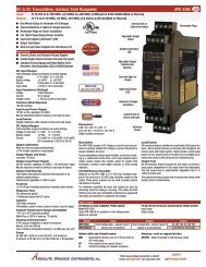
Description and Features<br />
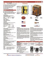
The <strong>API</strong> <strong>4300</strong> <strong>PLC</strong> and <strong>API</strong> <strong>4300</strong> D <strong>PLC</strong> accept a 4-<strong>20</strong> <strong>mA</strong> DC current input and<br />
provide an optically isolated 4-<strong>20</strong> <strong>mA</strong> DC current output that is linearly related to the<br />
input. Typical applications include signal isolation and ground loop elimination when<br />
using <strong>PLC</strong>s with single-ended (common ground) inputs. Full 3-way isolation (input,<br />
output, power) also makes this module useful for common mode signal rejection<br />
and noise pickup reduction.<br />
The <strong>API</strong> <strong>4300</strong> <strong>PLC</strong> and <strong>API</strong> <strong>4300</strong> D <strong>PLC</strong> have built-in 15 VDC loop excitation supplies<br />
for both the input and the output. Use of these loop power supplies is optional<br />
depending on how the unit is connected.<br />
The unit’s input power supply can be used to power passive 4-<strong>20</strong> <strong>mA</strong> input devices.<br />
If the input device provides its own power to the input loop, the non-powered input<br />
wiring terminals can be used.<br />
The unit’s output power supply can be used to power a passive 4-<strong>20</strong> <strong>mA</strong> <strong>PLC</strong><br />
input loop. If the <strong>PLC</strong> already provides power to the loop, the non-powered output<br />
terminals can be used.<br />
This often eliminates the need for an additional external power supply and additionally<br />
can provide a simple isolated solution for incompatible sink-sink and sourcesource<br />
I/O configurations.<br />
<strong>API</strong> exclusive features include two LoopTracker LEDs and a Functional Output<br />
Test. The LoopTracker LEDs (Green for input, Red for output) vary in intensity with<br />
changes in the process input and output signals. Monitoring the state of these LEDs<br />
can provide a quick visual picture of your process loop at all times.<br />
The Functional Output Test provides a fixed output (independent of the input) when<br />
activated. The test output level can be set to the desired level via the Cal. potentiometer.<br />
It operates using either the front Test push button or an external contact<br />
closure across terminals 4 and 6. This makes it useful as a manual override controllable<br />
from a remote location or by the <strong>PLC</strong>.<br />
Both the LoopTracker LEDs and Functional Output Test greatly aid in saving time<br />
during initial startup and/or troubleshooting.<br />
Models, Options & Accessories<br />
98.5 mm<br />
75 mm<br />
35 mm DIN<br />
Rail or Direct<br />
Panel Mount<br />
Output<br />
Ext. Test<br />
Free Factory<br />
I/O Setup!<br />
Input<br />
Power<br />
1 2 3<br />
4 5 6<br />
Span<br />
Zero<br />
Cal.<br />
Test<br />
7 8 9<br />
10 11 12<br />
Output<br />
LED<br />
Input<br />
LED<br />
Test<br />
Button<br />
Adjust<br />
Factory Configured—Please specify model and options<br />
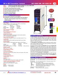
<strong>API</strong> <strong>4300</strong> <strong>PLC</strong> 4-<strong>20</strong> <strong>mA</strong> isolated transmitter, 85-265 VAC/VDC powered<br />
<strong>API</strong> <strong>4300</strong> D <strong>PLC</strong> 4-<strong>20</strong> <strong>mA</strong> isolated transmitter, 9-30 VAC/VDC powered<br />
Options—Add to end of model number, see price list for adder<br />
DF<br />
Fast response, 1 millisecond nominal response time<br />
M01<br />
Input/output reversal, 4-<strong>20</strong> <strong>mA</strong> in to <strong>20</strong>-4 <strong>mA</strong> out<br />
U<br />
Conformal coating for moisture resistance<br />
Accessories—Order as separate line item<br />
<strong>API</strong> TK36<br />
DIN rail, 35 mm W x 39" L, aluminum<br />
DC Input<br />
© 09-08<br />
BSOLUTE ROCESS NSTRUMENTS, Inc.<br />
12<strong>20</strong> American Way Libertyville, IL 60048<br />
Phone: 800-942-0315 Fax: 800-949-7502<br />
api-usa.com<br />
new
<strong>API</strong> <strong>4300</strong> <strong>PLC</strong>, <strong>API</strong> <strong>4300</strong> D <strong>PLC</strong> Installation and Setup<br />
DC Input<br />
RANGE<br />
The <strong>API</strong> <strong>4300</strong> <strong>PLC</strong> and <strong>API</strong> <strong>4300</strong> D <strong>PLC</strong> accept a 4-<strong>20</strong> <strong>mA</strong> DC current input and<br />
provide an optically isolated 4-<strong>20</strong> <strong>mA</strong> DC current output that is linearly related to the<br />
input. The versatility of the <strong>API</strong> <strong>4300</strong> <strong>PLC</strong> and <strong>API</strong> <strong>4300</strong> D <strong>PLC</strong> allows connection to<br />
active and passive 4-<strong>20</strong> <strong>mA</strong> sources.<br />
ELECTRICAL CONNECTIONS<br />
WARNING! All wiring must be performed by qualified personnel only. This module<br />
uses an industry-standard DIN rail mount. Order <strong>API</strong> TK36 DIN rail separately.<br />
Power Input Terminals<br />
The label on the side of the <strong>API</strong> module will indicate the power requirements.<br />
Power is connected to terminals 10 and 12. When using DC power, either polarity is<br />
acceptable, but for consistency with similar <strong>API</strong> products, negative (–) can be wired<br />
to terminal 10 and positive (+) can be wired to terminal 12.<br />
Sink vs. Source<br />
When connecting 4-<strong>20</strong> <strong>mA</strong> devices it is important to keep in mind which device<br />
will provide power the current loop. A transmitter that has a powered current output<br />
(typically a 4-wire transmitter) sources current and is connected to a receiving<br />
device that sinks current. A passive transmitter (typically a 2-wire transmitter) sinks<br />
current and is connected to a receiving device that sources current.<br />
Similarly, a <strong>PLC</strong> input that is passive or unpowered must be connected to a transmitter<br />
that provides power to the loop. A <strong>PLC</strong> input that provides power to the loop<br />
must be connected to a transmitter that has a passive output.<br />
In the following wiring instructions sink/source is from the reference point of the<br />
<strong>API</strong> <strong>4300</strong>.<br />
Current Sinking Input (7–, 8+)<br />
Your transmitter or sensor provides power to the <strong>API</strong> <strong>4300</strong> input loop. Polarity must<br />
be observed when connecting the signal input. The negative (–) connection is made<br />
to terminal 7 and the positive connection (+) is made to terminal 8.<br />
Current Sourcing Input (8–, 9+)<br />
Your transmitter or sensor is a passive device and the <strong>API</strong> <strong>4300</strong> input loop provides<br />
the power to it. Polarity must be observed when connecting the signal input. Your<br />
passive input device is powered by the 15 volt DC power supply at terminal 9. The<br />
negative (–) connection is made to terminal 8 and the positive connection (+) is made<br />
to terminal 9.<br />
Current Sinking Output (2+, 3–)<br />
Your <strong>PLC</strong> or receiving device provides power to the loop and the <strong>API</strong> <strong>4300</strong> output<br />
acts as a passive device. Polarity must be observed when connecting the signal<br />
output. The negative (–) connection is made to terminal 3 and the positive connection<br />
(+) is made to terminal 2.<br />
Current Sourcing Output (1+, 2–)<br />
Your <strong>PLC</strong> or receiving device has a passive input and the <strong>API</strong> <strong>4300</strong> output provides<br />
power to the loop. Polarity must be observed when connecting the signal input.<br />
Your passive input device is powered by the 15 volt DC power supply at terminal 1.<br />
The negative (–) connection is made to terminal 2 and the positive connection (+) is<br />
made to terminal 1.<br />
External Test Switch (4, 6)<br />
A customer-supplied external switch can be used across terminals 4 and 6 to remotely<br />
operate the Functional Output Test. Do not apply power to these terminals.<br />
CALIBRATION<br />
Input and output ranges are pre-configured at the factory for 4-<strong>20</strong> <strong>mA</strong>. Frontmounted<br />
Zero and Span potentiometers can be used should fine-tuning be necessary.<br />
1. Apply power to the module and allow a minimum <strong>20</strong> minute warm up time.<br />
2. Using an accurate 4-<strong>20</strong> <strong>mA</strong> calibration source, provide a 4 <strong>mA</strong> input to the module.<br />
3. Using an accurate milliamp meter for the output, adjust the Zero potentiometer<br />
for 4 <strong>mA</strong> output. The Zero control should only be adjusted when the input signal<br />
is at its minimum.<br />
4. Set the input to <strong>20</strong> <strong>mA</strong><br />
5. Using an accurate milliamp meter for the output, adjust the Span potentiometer<br />
for <strong>20</strong> <strong>mA</strong> output. The Span control should only be adjusted when the input<br />
signal is at its maximum.<br />
6. Repeat adjustments for maximum accuracy.<br />
FUNCTIONAL OUTPUT TEST<br />
The Functional Output Test may be used to drive the device on the output side of the<br />
loop (a <strong>PLC</strong>, panel meter, chart recorder, etc.) with a known good signal. This can be<br />
used as a system diagnostic aid during initial start-up or during troubleshooting.<br />
Press the Test button to set the output to the test level. When the button is released,<br />
the output will return to normal. It can also operate using an external contact closure<br />
across terminals 4 and 6.<br />
The test signal level is factory set to approximately 12 <strong>mA</strong>. The front-mounted Cal.<br />
potentiometer can be used to adjust the test level from approximately 4 to <strong>20</strong> <strong>mA</strong>.<br />
Connect a <strong>mA</strong> meter to the output, hold the test button and turn the Cal. potentiometer<br />
to set the test level to the desired value.<br />
OPERATION<br />
The <strong>API</strong> <strong>4300</strong> <strong>PLC</strong> and <strong>API</strong> <strong>4300</strong> D <strong>PLC</strong> accept a 4-<strong>20</strong> <strong>mA</strong> DC current input and<br />
provide an optically isolated 4-<strong>20</strong> <strong>mA</strong> DC current output that is linearly related to the<br />
input. The input is filtered, isolated, and passed to the output stage.<br />
GREEN LoopTracker ® Input LED<br />
Provides a visual indication that a signal is being sensed by the input circuitry of<br />
the module. It also indicates the input signal strength by changing in intensity as the<br />
process changes from minimum to maximum. If the LED fails to illuminate, or fails<br />
to change in intensity as the process changes, this may indicate a problem with<br />
module power or signal input wiring.<br />
RED LoopTracker output LED<br />
Provides a visual indication that the output signal is functioning. It becomes brighter<br />
as the input and the corresponding output change from minimum to maximum. For<br />
current outputs, the RED LED will only light if the output loop current path is complete.<br />
For either current or voltage outputs, failure to illuminate or a failure to change<br />
in intensity as the process changes may indicate a problem with the module power<br />
or signal output wiring.<br />
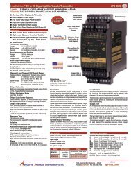
<strong>API</strong> <strong>4300</strong> <strong>PLC</strong>, <strong>API</strong> <strong>4300</strong> D <strong>PLC</strong><br />
current sinking output<br />
current sinking input<br />
<strong>API</strong> <strong>4300</strong> <strong>PLC</strong>, <strong>API</strong> <strong>4300</strong> D <strong>PLC</strong><br />
current sourcing output<br />
current sourcing input<br />
<strong>API</strong> <strong>4300</strong> <strong>PLC</strong>, <strong>API</strong> <strong>4300</strong> D <strong>PLC</strong><br />
current sourcing output<br />
current sinking input<br />
<strong>API</strong> <strong>4300</strong> <strong>PLC</strong>, <strong>API</strong> <strong>4300</strong> D <strong>PLC</strong><br />
current sinking output<br />
current sourcing input<br />
4-<strong>20</strong> <strong>mA</strong><br />
<strong>PLC</strong><br />
Input<br />
Power<br />
(–)<br />
(+)<br />
2(+), 3(–) signal output<br />
1, 5 no connection<br />
4, 6 ext. test switch<br />
(+) (–)<br />
1 2 3<br />
4 5 6<br />
4-<strong>20</strong> <strong>mA</strong><br />
<strong>PLC</strong><br />
Input<br />
(–)<br />
15 VDC (+) (–)<br />
(+)<br />
1 2 3<br />
1(+), 2(–) signal output<br />
3, 5 no connection<br />
4, 6 ext. test switch<br />
4 5 6<br />
4-<strong>20</strong> <strong>mA</strong><br />
<strong>PLC</strong><br />
Input<br />
(–)<br />
15 VDC (+) (–)<br />
(+)<br />
1 2 3<br />
2(+), 3(–) signal output<br />
3, 5 no connection<br />
4, 6 ext. test switch<br />
4 5 6<br />
4-<strong>20</strong> <strong>mA</strong><br />
<strong>PLC</strong><br />
Input<br />
Power<br />
(–)<br />
(+)<br />
1(+), 2(–) signal output<br />
1, 5 no connection<br />
4, 6 ext. test switch<br />
(+) (–)<br />
1 2 3<br />
4 5 6<br />
Ext.<br />
power<br />
3 or 4 wire (+)<br />
4-<strong>20</strong> <strong>mA</strong><br />
Xmtr (–)<br />
7(–), 8(+) signal input<br />
9 no connection<br />
(–) (+)<br />
7 8 9<br />
10 11 12<br />
2 wire (+)<br />
4-<strong>20</strong> <strong>mA</strong><br />
Xmtr (–)<br />
8(–), 9(+) signal input<br />
7 no connection<br />
15 VDC<br />
(–) (+)<br />
7 8 9<br />
10 11 12<br />
10 Power AC or DC<br />
11 Earth ground<br />
12 Power AC or DC<br />
10 Power AC or DC<br />
11 Earth ground<br />
12 Power AC or DC<br />
10 Power AC or DC<br />
11 Earth ground<br />
12 Power AC or DC<br />
10 Power AC or DC<br />
11 Earth ground<br />
12 Power AC or DC<br />
<strong>API</strong> <strong>4300</strong> <strong>PLC</strong>: Powered by 85-265 VAC/VDC<br />
<strong>API</strong> <strong>4300</strong> D <strong>PLC</strong>: Powered by 9-30 VAC/VDC<br />
<strong>API</strong> maintains a constant effort to upgrade and improve its products. Specifications<br />
are subject to change without notice. Consult factory for your specific requirements.<br />
new BSOLUTE ROCESS NSTRUMENTS, Inc.<br />
12<strong>20</strong> American Way Libertyville, IL 60048<br />
Phone: 800-942-0315 Fax: 800-949-7502<br />
For latest product information or to contact<br />
your local representative visit api-usa.com<br />
© 09-08