FUEL INJECTION SYSTEM – BOSCH AFC - CelicaTech
FUEL INJECTION SYSTEM – BOSCH AFC - CelicaTech
FUEL INJECTION SYSTEM – BOSCH AFC - CelicaTech
Create successful ePaper yourself
Turn your PDF publications into a flip-book with our unique Google optimized e-Paper software.
£<br />
£<br />
£<br />
£<br />
£<br />
£<br />
£<br />
£<br />
£<br />
£<br />
£<br />
£<br />
Disconnect coolant temperature sensor connector. Using an<br />
ohmmeter, measure resistance between sensor terminals. See COOLANT<br />
TEMPERATURE SENSOR RESISTANCE table.<br />
COOLANT TEMPERATURE SENSOR RESISTANCE TABLE<br />
¡¡¡¡¡¡¡¡¡¡¡¡¡¡¡¡¡¡¡¡¡¡¡¡¡¡¡¡¡¡¡¡¡¡¡¡¡¡¡¡¡¡¡¡¡¡¡¡¡¡¡¡¡¡¡¡¡¡<br />
¡<br />
Temperature<br />
Ohms<br />
-4 F (-20 C) ............................... 10,000-20,000<br />
32 F (0 C) ...................................... 400-7000<br />
68 F (20 C) .................................... 2000-3000<br />
104 F (40 C) .................................... 900-1300<br />
140 F (60 C) ..................................... 400-700<br />
176 F (80 C) ..................................... 200-400<br />
¡ ¡ ¡ ¡ ¡ ¡ ¡ ¡ ¡ ¡ ¡ ¡ ¡ ¡ ¡ ¡ ¡ ¡ ¡ ¡ ¡ ¡ ¡ ¡ ¡ ¡ ¡ ¡ ¡ ¡ ¡ ¡ ¡ ¡ ¡ ¡ ¡ ¡ ¡ ¡ ¡ ¡ ¡ ¡ ¡ ¡ ¡ ¡ ¡ ¡ ¡ ¡ ¡ ¡ ¡ ¡ ¡ ¡ ¡<br />
REMOVAL & INSTALLATION<br />
* PLEASE READ THIS FIRST *<br />
CAUTION: The fuel injection system maintains constant fuel pressure<br />
in fuel lines and component parts at all times. Always<br />
relieve fuel pressure before attempting to open system for<br />
testing or replacement of components. Do not allow fuel to<br />
flow onto engine or electrical parts. Do not allow open<br />
flame or sparks in area while servicing components.<br />
Disconnect negative battery cable before disconnecting any<br />
electrical component.<br />
ELECTRONIC CONTROL UNIT (ECU)<br />
Removal & Installation<br />
Disconnect negative battery cable. Clear area for access to<br />
ECU. Disconnect electrical connector lock lever (if used) and<br />
carefully remove connector. Remove ECU retaining screws and remove<br />
ECU. To install, reverse removal procedure.<br />
AIRFLOW METER<br />
Removal & Installation<br />
Disconnect negative battery cable. Disconnect air ducts and<br />
hoses connecting air cleaner and airflow meter. Remove air cleaner<br />
cover, if required. Remove airflow meter retaining bolts. Unplug<br />
airflow meter electrical connector and remove airflow meter. To<br />
install, reverse removal procedure.<br />
THROTTLE POSITION SENSOR<br />
Removal & Installation<br />
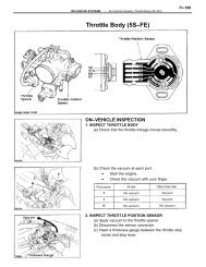
1) Disconnect negative battery cable. Unplug TPS electrical<br />
connector. Remove 2 screws securing TPS to housing. Remove by slowly<br />
pulling sensor off throttle shaft.<br />
2) To install, reverse removal procedure. Make sure sensor is<br />
aligned on throttle shaft and after replacement, perform TPS<br />
adjustment. See ADJUSTMENTS in this article.<br />
COLD START INJECTOR<br />
Removal & Installation<br />
Disconnect negative battery cable and remove electrical<br />
connector from cold start injector. Relieve fuel system pressure and


