FUEL INJECTION SYSTEM – BOSCH AFC - CelicaTech
FUEL INJECTION SYSTEM – BOSCH AFC - CelicaTech
FUEL INJECTION SYSTEM – BOSCH AFC - CelicaTech
You also want an ePaper? Increase the reach of your titles
YUMPU automatically turns print PDFs into web optimized ePapers that Google loves.
<strong>FUEL</strong> <strong>INJECTION</strong> <strong>SYSTEM</strong> - <strong>BOSCH</strong> <strong>AFC</strong><br />
1988 Toyota Celica<br />
1988 <strong>FUEL</strong> <strong>INJECTION</strong><br />
Bosch <strong>AFC</strong><br />
Toyota; Camry, Celica, Corolla, Cressida, Land Cruiser, MR2,<br />
Pickup, Supra, Van, 4Runner<br />
DESCRIPTION<br />
NOTE: For specifications on Throttle Position Sensor (TPS), idle<br />
speed and mixture, and fuel pump output volume, see<br />
appropriate article in TUNE-UP PROCEDURES section.<br />
The Bosch <strong>AFC</strong> (L-Jetronic) fuel injection system is used on<br />
all models. However, variations may exist between model applications.<br />
This article covers the Bosch <strong>AFC</strong> system in general, with<br />
manufacturers’ differences noted under SPECIAL FEATURES. For computer<br />
control information, see the appropriate article in 1988 COMPUTERIZED<br />
ENGINE CONTROLS section.<br />
The Bosch Airflow Controlled (<strong>AFC</strong>) fuel injection system is<br />
an electronically controlled system operated by incoming airflow. Some<br />
vehicles are equipped with a potentiometer to measure incoming air<br />
flow, while other vehicles use a hot wire type airflow sensor.<br />
The <strong>AFC</strong> fuel injection system also contains a feedback system<br />
which measures oxygen content of exhaust gases and maintains the<br />
air/fuel ratio at about 14.7:1.<br />
The fuel injection system consists of an electric fuel pump,<br />
fuel pressure regulator, fuel damper, fuel injectors, cold start<br />
injector, Electronic Control Unit (ECU), and airflow meter. In<br />
addition, an air temperature sensor, throttle position sensor, coolant<br />
temperature sensor, oxygen sensor, catalytic converter, auxiliary air<br />
valve, idle speed control valve, throttle body, and electrical relays<br />
are used.<br />
NOTE: Not all models use all components.<br />
OPERATION<br />
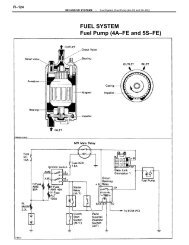
ELECTRIC <strong>FUEL</strong> PUMP(S)<br />
Fuel under pressure from electric fuel pump flows through a<br />
fuel damper, fuel filter, injector fuel rail and fuel pressure<br />
regulator. Fuel pump(s) may be located on frame rail, in fuel tank or<br />
both. Electrical power for fuel pump operation during cranking mode is<br />
provided from starter relay via the fuel pump relay (if equipped) and<br />
ECU.<br />
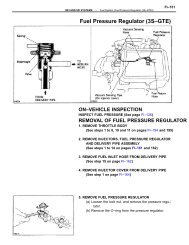
<strong>FUEL</strong> PRESSURE REGULATOR<br />
The pressure regulator is a sealed unit which is divided by a<br />
diaphragm into 2 chambers (fuel and spring chambers). The fuel chamber<br />
receives fuel through the inlet side (both sides on Subaru 1.8L) from<br />
the injector fuel rail. The spring chamber is connected to intake<br />
manifold vacuum.<br />
At idle, intake manifold vacuum is high. The diaphragm is<br />
pulled down by intake manifold vacuum. Any excessive fuel is returned<br />
to the fuel tank. As the throttle is depressed, intake manifold vacuum<br />
decreases. The regulator spring overcomes manifold vacuum increasing<br />
fuel pressure.
<strong>FUEL</strong> INJECTORS<br />
A fuel rail links the fuel pressure regulator with the fuel<br />
injectors. Each cylinder is provided with a solenoid-operated injector<br />
which sprays fuel toward the back of each intake valve.<br />
ELECTRONIC CONTROL UNIT (ECU)<br />
All components of the control system are electrically<br />
connected to the ECU. The ECU is a pre-programmed computer which<br />
receives and interprets data from various sensors to calculate the<br />
amount of fuel required by the engine to maintain efficiency with<br />
minimum exhaust emissions. The oxygen sensor informs the ECU of oxygen<br />
content of exhaust gases and the ECU constantly adjusts the air/fuel<br />
ratio by controlling the injector "on" time.<br />
An automatic function of the ECU is to provide fuel<br />
enrichment whenever engine is cranked, regardless of engine<br />
temperature. This is activated by a direct electrical connection from<br />
the starter circuit to the ECU (most models). The ECU is a sealed<br />
unit, and no service is required.<br />
AIRFLOW METER<br />
Hot Wire Type<br />
The airflow meter continually measures temperature, amount,<br />
density, and speed of air entering engine intake system. The meter<br />
consists of a platinum wire filament located within intake air stream.<br />
The wire filament is kept at a constant temperature above<br />
that of air entering engine regardless of composition of air entering<br />
engine. The airflow meter sends a temperature related signal to be<br />
processed by the ECU. See Fig. 1.<br />
Fig. 1: Hot Wire Airflow Meter (Typical)<br />
Potentiometer Type<br />
This airflow meter uses a movable vane connected to a<br />
potentiometer. As air entering the engine moves the vane, the
potentiometer is moved informing the ECU on the amount of air entering<br />
the engine. Some potentiometer airflow meters use an air temperature<br />
sensor located inside the airflow meter air passage. See Fig. 2.<br />
Fig. 2: Potentiometer Airflow Meter (Typical)<br />
AIR TEMPERATURE SENSOR<br />
The air temperature sensor is an integral component of the<br />
airflow meter which converts temperature of incoming air into<br />
electrical signals. These signals are received by the ECU and<br />
processed to adjust the amount of fuel delivered by the injectors. The<br />
air temperature sensor is not serviceable.<br />
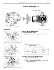
THROTTLE POSITION SENSOR (TPS)<br />
A contact-type TPS is installed on the throttle chamber. It<br />
converts throttle position into electrical signals to inform ECU of<br />
throttle position. Signals are sent to ECU when throttle is fully open<br />
or at idle. See Fig. 3. Some models send a specific signal to ECU,<br />
depending on throttle angle. The open contacts prevent loss of power
during sudden acceleration/deceleration by signaling ECU of the<br />
required fuel enrichment.<br />
Fig. 3: Contact-Type Throttle Position Sensor (Typical)<br />
COOLANT TEMPERATURE SENSOR<br />
This sensor provides ECU with engine temperature information<br />
relating to warm-up enrichment operation. Some models use a dualsensor<br />
element which also signals the ignition computer (if equipped).<br />
During warm-up period after a cold engine start, additional<br />
fuel is required to maintain engine performance. As engine temperature<br />
increases, the ECU decreases fuel enrichment until engine reaches<br />
normal operating temperature.<br />
ELECTRICAL RELAYS<br />
The various relays used with the electronic controls of the<br />
<strong>AFC</strong> injection system control power to injectors, fuel pump, ECU, and<br />
cold start system. The electrical relays may consist of one component<br />
for all relays or a combination of individual relays.
AUXILIARY AIR VALVE<br />
Most models with Bosch <strong>AFC</strong> fuel injection use an Auxiliary<br />
Air Valve (AAV) to shorten engine warm-up time. The AAV supplies<br />
additional air into the intake system which increases engine RPM<br />
during a cold start.<br />
The AAV consists of an electrically heated bi-metallic strip,<br />
movable disc, and air by-pass channel. The heater coil on the bimetallic<br />
strip is energized by the fuel pump relay. Control of the<br />
valve is based upon engine temperature; the air by-pass channel is<br />
open when engine is cold and gradually closes as temperature rises. At<br />
predetermined temperatures, air by-pass channel is blocked and<br />
additional airflow stops. See Fig. 4.<br />
Fig. 4: Auxiliary Air Valve (Typical)<br />
COLD START INJECTOR<br />
Most models use a cold start injector which delivers
additional fuel, and a start injector time switch which controls<br />
operation of the cold start injector. The start injector time switch<br />
limits cold start injection to 1-12 seconds, depending upon engine<br />
coolant temperature. When engine coolant temperature rises above a<br />
specified point, bi-metallic contact breaks ground circuit of cold<br />
start injector and cold start enrichment is by-passed.<br />
SPECIAL FEATURES<br />
AIRFLOW METER<br />
All models except Supra, use a potentiometer type airflow<br />
meter incorporating an air temperature sensor. Supra models use an<br />
airflow meter which has a lumimus diode and a photo transistor. The<br />
lumimus diode emits light which reflects off of a mirror to the photo<br />
transistor.<br />
The airflow meter causes incoming air to swirl into a vortex.<br />
When air swirls, it vibrates a leaf spring which has the mirror<br />
attached to it. As the mirror moves, the photo transistor picks up the<br />
movement of reflected light. The airflow meter sends this signal to<br />
the ECU.<br />
<strong>FUEL</strong> PULSATION DAMPER<br />
All models except Celica, Corolla FX-16, MR2 and Supra turbo<br />
use a fuel pulsation damper. The function of the damper is to<br />
eliminate fuel pressure surges during vehicle operation.<br />
TESTING<br />
* PLEASE READ THIS FIRST *<br />
NOTE:<br />
For testing of fuel system components not covered in this<br />
article, refer to appropriate article in 1988 COMPUTERIZED<br />
ENGINE CONTROLS section.<br />
ELECTRONIC CONTROL UNIT (ECU)<br />
Do not attempt to test ECU, as permanent damage could result.<br />
It is possible to check wires for continuity. The ECU should only by<br />
judged faulty after compression is checked, ignition system has been<br />
tested and found problem-free, and all other fuel injection components<br />
have been thoroughly tested (including wiring).<br />
NOTE:<br />
<strong>AFC</strong> electrical systems can be checked by using Electronic<br />
Fuel Injection testers prescribed by the manufacturer.<br />
Instructions for use of testers must be followed carefully<br />
to prevent damage to system.<br />
<strong>FUEL</strong> INJECTORS & RESISTORS<br />
1) Connect tachometer to engine. Start engine and run at<br />
idle. Remove harness connector from injectors one at a time. Engine<br />
idle speed should drop 100-300 RPM as each injector is disconnected.<br />
If engine idle speed does not drop, check the wiring connector,<br />
injector resistance or injection signal from the computer.<br />
2) Disconnect electrical connector from each injector.<br />
Measure injector resistance. See INJECTOR RESISTANCE SPECIFICATIONS<br />
table. If injector is not to specification, replace injector.<br />
INJECTOR RESISTANCE SPECIFICATIONS TABLE
¢<br />
¢<br />
¢<br />
¡¡¡¡¡¡¡¡¡¡¡¡¡¡¡¡¡¡¡¡¡¡¡¡¡¡¡¡¡¡¡¡¡¡¡¡¡¡¡¡¡¡¡¡¡¡¡¡¡¡¡¡¡¡¡¡¡¡<br />
¡<br />
Application<br />
Ohms<br />
Camry<br />
4-Cyl. ............................................. 1.6<br />
V6 ................................................ 13.8<br />
Celica .............................................. 13.8<br />
Celica All-Trac ...................................... 2-4<br />
Corolla (All Models) ................................. 13.8<br />
Cressida ........................................... 1.5-3<br />
Land Cruiser ........................................ 13.8<br />
MR2 ................................................. 13.8<br />
Pickup & 4Runner<br />
4-Cyl. (Non-Turbo) ............................... 1-2.5<br />
4-Cyl. (Turbo) ................................... 1.1-2<br />
V6 ............................................. 1.2-2.2<br />
Supra<br />
Non-Turbo ...................................... 1.8-3.4<br />
Turbo .......................................... 2.0-3.8<br />
Van .............................................. 1.1-2.2<br />
¡ ¡ ¡ ¡ ¡ ¡ ¡ ¡ ¡ ¡ ¡ ¡ ¡ ¡ ¡ ¡ ¡ ¡ ¡ ¡ ¡ ¡ ¡ ¡ ¡ ¡ ¡ ¡ ¡ ¡ ¡ ¡ ¡ ¡ ¡ ¡ ¡ ¡ ¡ ¡ ¡ ¡ ¡ ¡ ¡ ¡ ¡ ¡ ¡ ¡ ¡ ¡ ¡ ¡ ¡ ¡ ¡ ¡ ¡<br />
<strong>FUEL</strong> PRESSURE<br />
CAUTION: Constant fuel pressure is maintained in fuel lines and<br />
component parts at all times. Relieve pressure before<br />
attempting to open system for testing. Do not allow fuel to<br />
flow onto engine or electrical parts or allow an open flame<br />
in area while testing fuel system components.<br />
Relieve fuel system pressure. Connect fuel pressure gauge in<br />
fuel system after fuel pressure regulator. Check fuel pressure at<br />
engine idle with fuel pressure regulator vacuum hose connected and<br />
disconnected. See <strong>FUEL</strong> PUMP PRESSURE SPECIFICATIONS table. Fuel system<br />
residual pressure should be 21 psi (1.5 kg/cm ) for 5 minutes on all<br />
models.<br />
<strong>FUEL</strong> PUMP PRESSURE SPECIFICATIONS TABLE<br />
No Vacuum<br />
psi (kg/cm<br />
Vacuum<br />
) psi (kg/cm )<br />
¡ ¡ ¡ ¡ ¡ ¡ ¡ ¡ ¡ ¡ ¡ ¡ ¡ ¡ ¡ ¡ ¡ ¡ ¡ ¡ ¡ ¡ ¡ ¡ ¡ ¡ ¡ ¡ ¡ ¡ ¡ ¡ ¡ ¡ ¡ ¡ ¡ ¡ ¡ ¡ ¡ ¡ ¡ ¡ ¡ ¡ ¡ ¡ ¡ ¡ ¡ ¡ ¡ ¡ ¡ ¡ ¡ ¡ ¡<br />
Application<br />
Camry, Celica (3S-FE),<br />
Pickup & 4Runner<br />
(22-RE & V6) ............... 38-44 ............ 33-37<br />
Celica (3S-GE & All-Trac),<br />
Cressida, Pickup & 4Runner .. 33-38 ............ 27-31<br />
Corolla, MR2 & Van ............ 38-44 ............ 30-33<br />
Land Cruiser .................. 37-46 ............ 33-37<br />
Supra ......................... 33-40 ............ 23-30<br />
¡ ¡ ¡ ¡ ¡ ¡ ¡ ¡ ¡ ¡ ¡ ¡ ¡ ¡ ¡ ¡ ¡ ¡ ¡ ¡ ¡ ¡ ¡ ¡ ¡ ¡ ¡ ¡ ¡ ¡ ¡ ¡ ¡ ¡ ¡ ¡ ¡ ¡ ¡ ¡ ¡ ¡ ¡ ¡ ¡ ¡ ¡ ¡ ¡ ¡ ¡ ¡ ¡ ¡ ¡ ¡ ¡ ¡ ¡<br />
AIR TEMPERATURE SENSOR<br />
Information not available from manufacture.<br />
AIRFLOW METER<br />
Disconnect airflow meter connector. Using an ohmmeter,<br />
measure resistance across meter terminals. On Supra Turbo models, an<br />
analog ohmmeter must be used. Supra Turbo models have a 5-terminal<br />
airflow meter connector. See Fig. 5. For airflow meter specifications,<br />
see AIRFLOW METER RESISTANCE table.
Fig. 5: Airflow Meter Terminal Identification<br />
Courtesy of Toyota Motor Sales, U.S.A., Inc.<br />
AIRFLOW METER RESISTANCE TABLE<br />
Application<br />
Terminals<br />
¡ ¡ ¡ ¡ ¡ ¡ ¡ ¡ ¡ ¡ ¡ ¡ ¡ ¡ ¡ ¡ ¡ ¡ ¡ ¡ ¡ ¡ ¡ ¡ ¡ ¡ ¡ ¡ ¡ ¡ ¡ ¡ ¡ ¡ ¡ ¡ ¡ ¡ ¡ ¡ ¡ ¡ ¡ ¡ ¡ ¡ ¡ ¡ ¡ ¡ ¡ ¡ ¡ ¡ ¡ ¡ ¡ ¡ ¡<br />
Ohms<br />
Camry, Celica, Land Cruiser,<br />
Pickup & 4Runner & Supra Non-Turbo<br />
E2-Vc ......................................... 200-400<br />
E1-Fc<br />
Measuring Plate Fully Closed ............... Infinity<br />
Measuring Plate Other Than Closed ................. 0<br />
E2-Vs<br />
Measuring Plate Fully Closed ................ 200-600<br />
Measuring Plate Fully Open .................. 20-1200<br />
Corolla<br />
E2-Vc .......................................... 100-300<br />
E2-Vb .......................................... 200-400<br />
E1-Fc<br />
Measuring Plate Fully Closed ................ Infinity<br />
Measuring Plate Other Than Closed .................. 0<br />
E2-Vs<br />
Measuring Plate Fully Closed .................. 20-400<br />
Measuring Plate Fully Open ................... 20-3000<br />
Cressida, MR2 & Van<br />
E2-Vc<br />
Cressida ..................................... 200-400<br />
MR2 & Van .................................... 100-300<br />
E2-Vb<br />
MR2 & Van .................................... 200-400
£<br />
£<br />
£<br />
£<br />
£<br />
£<br />
£<br />
£<br />
£<br />
£<br />
E1-Fc<br />
Measuring Plate Fully Closed ................ Infinity<br />
Measuring Plate Other Than Closed .................. 0<br />
E2-Vs<br />
Cressida ..................................... 20-1200<br />
MR2 .......................................... 20-3000<br />
Van .......................................... 20-1000<br />
Supra Turbo<br />
Ks-E1 ......................................... Infinity<br />
E1-Ks ...................................... 5000-10,000<br />
Vc-E1 .................................... 10,000-15,000<br />
E1-Vc ...................................... 5000-10,000<br />
All Models<br />
E2-THA<br />
-4 F (20 C) ............................ 10,000-20,000<br />
32 F (0 C) ................................. 4000-7000<br />
68 F (20 C) ................................ 2000-3000<br />
104 F (40 C) ................................ 900-1300<br />
140 F (60 C) ................................. 400-700<br />
¡ ¡ ¡ ¡ ¡ ¡ ¡ ¡ ¡ ¡ ¡ ¡ ¡ ¡ ¡ ¡ ¡ ¡ ¡ ¡ ¡ ¡ ¡ ¡ ¡ ¡ ¡ ¡ ¡ ¡ ¡ ¡ ¡ ¡ ¡ ¡ ¡ ¡ ¡ ¡ ¡ ¡ ¡ ¡ ¡ ¡ ¡ ¡ ¡ ¡ ¡ ¡ ¡ ¡ ¡ ¡ ¡ ¡ ¡<br />
AUXILIARY AIR VALVE<br />
Ensure engine is cold, then start engine. Pinch rubber hose<br />
between air valve and throttle chamber. Engine speed should decrease.<br />
After engine reaches operating temperature, pinch hose again. Engine<br />
speed should not decrease more than 50 RPM. If valve does not operate<br />
as outlined, replace auxiliary air valve.<br />
ALTITUDE COMPENSATOR SENSOR<br />
NOTE:<br />
Refer to appropriate article in 1988 COMPUTERIZED ENGINE<br />
CONTROLS section.<br />
IDLE SPEED CONTROLLER (ISC) VALVE<br />
NOTE:<br />
Refer to appropriate article in 1988 COMPUTERIZED ENGINE<br />
CONTROLS section.<br />
COLD START INJECTOR<br />
Disconnect cold start injector connector. Using an ohmmeter,<br />
measure resistance between injector terminals. See COLD START INJECTOR<br />
RESISTANCE table.<br />
COLD START INJECTOR RESISTANCE TABLE<br />
¡¡¡¡¡¡¡¡¡¡¡¡¡¡¡¡¡¡¡¡¡¡¡¡¡¡¡¡¡¡¡¡¡¡¡¡¡¡¡¡¡¡¡¡¡¡¡¡¡¡¡¡¡¡¡¡¡¡<br />
¡<br />
Application<br />
Ohms<br />
Camry, Celica (Non-Turbo),<br />
Land Cruiser, Pickup & 4Runner & Supra ............. 2-4<br />
Celica (Turbo), Corolla,<br />
Cressida & Van ..................................... 3-5<br />
¡ ¡ ¡ ¡ ¡ ¡ ¡ ¡ ¡ ¡ ¡ ¡ ¡ ¡ ¡ ¡ ¡ ¡ ¡ ¡ ¡ ¡ ¡ ¡ ¡ ¡ ¡ ¡ ¡ ¡ ¡ ¡ ¡ ¡ ¡ ¡ ¡ ¡ ¡ ¡ ¡ ¡ ¡ ¡ ¡ ¡ ¡ ¡ ¡ ¡ ¡ ¡ ¡ ¡ ¡ ¡ ¡ ¡ ¡<br />
THERMO TIME SWITCH<br />
NOTE:<br />
Refer to appropriate article in 1988 COMPUTERIZED ENGINE<br />
CONTROLS section.<br />
COOLANT TEMPERATURE SENSOR
£<br />
£<br />
£<br />
£<br />
£<br />
£<br />
£<br />
£<br />
£<br />
£<br />
£<br />
£<br />
Disconnect coolant temperature sensor connector. Using an<br />
ohmmeter, measure resistance between sensor terminals. See COOLANT<br />
TEMPERATURE SENSOR RESISTANCE table.<br />
COOLANT TEMPERATURE SENSOR RESISTANCE TABLE<br />
¡¡¡¡¡¡¡¡¡¡¡¡¡¡¡¡¡¡¡¡¡¡¡¡¡¡¡¡¡¡¡¡¡¡¡¡¡¡¡¡¡¡¡¡¡¡¡¡¡¡¡¡¡¡¡¡¡¡<br />
¡<br />
Temperature<br />
Ohms<br />
-4 F (-20 C) ............................... 10,000-20,000<br />
32 F (0 C) ...................................... 400-7000<br />
68 F (20 C) .................................... 2000-3000<br />
104 F (40 C) .................................... 900-1300<br />
140 F (60 C) ..................................... 400-700<br />
176 F (80 C) ..................................... 200-400<br />
¡ ¡ ¡ ¡ ¡ ¡ ¡ ¡ ¡ ¡ ¡ ¡ ¡ ¡ ¡ ¡ ¡ ¡ ¡ ¡ ¡ ¡ ¡ ¡ ¡ ¡ ¡ ¡ ¡ ¡ ¡ ¡ ¡ ¡ ¡ ¡ ¡ ¡ ¡ ¡ ¡ ¡ ¡ ¡ ¡ ¡ ¡ ¡ ¡ ¡ ¡ ¡ ¡ ¡ ¡ ¡ ¡ ¡ ¡<br />
REMOVAL & INSTALLATION<br />
* PLEASE READ THIS FIRST *<br />
CAUTION: The fuel injection system maintains constant fuel pressure<br />
in fuel lines and component parts at all times. Always<br />
relieve fuel pressure before attempting to open system for<br />
testing or replacement of components. Do not allow fuel to<br />
flow onto engine or electrical parts. Do not allow open<br />
flame or sparks in area while servicing components.<br />
Disconnect negative battery cable before disconnecting any<br />
electrical component.<br />
ELECTRONIC CONTROL UNIT (ECU)<br />
Removal & Installation<br />
Disconnect negative battery cable. Clear area for access to<br />
ECU. Disconnect electrical connector lock lever (if used) and<br />
carefully remove connector. Remove ECU retaining screws and remove<br />
ECU. To install, reverse removal procedure.<br />
AIRFLOW METER<br />
Removal & Installation<br />
Disconnect negative battery cable. Disconnect air ducts and<br />
hoses connecting air cleaner and airflow meter. Remove air cleaner<br />
cover, if required. Remove airflow meter retaining bolts. Unplug<br />
airflow meter electrical connector and remove airflow meter. To<br />
install, reverse removal procedure.<br />
THROTTLE POSITION SENSOR<br />
Removal & Installation<br />
1) Disconnect negative battery cable. Unplug TPS electrical<br />
connector. Remove 2 screws securing TPS to housing. Remove by slowly<br />
pulling sensor off throttle shaft.<br />
2) To install, reverse removal procedure. Make sure sensor is<br />
aligned on throttle shaft and after replacement, perform TPS<br />
adjustment. See ADJUSTMENTS in this article.<br />
COLD START INJECTOR<br />
Removal & Installation<br />
Disconnect negative battery cable and remove electrical<br />
connector from cold start injector. Relieve fuel system pressure and
emove fuel supply line from injector. Remove injector retaining bolts<br />
and remove injector. To install, reverse removal procedure.<br />
AUXILIARY AIR VALVE<br />
NOTE:<br />
Replacement of auxiliary air valve on Toyota models requires<br />
that immediate replacement be available or cooling system be<br />
drained to below level of valve.<br />
Removal & Installation<br />
Disconnect negative battery cable and remove electrical<br />
connector from air valve. Drain engine coolant, if required. Remove<br />
air hoses and coolant hoses (if equipped). Remove retaining bolts and<br />
remove air valve. To install, reverse removal procedure.<br />
COOLANT TEMPERATURE SENSOR<br />
NOTE:<br />
Replacement of temperature sensor requires immediate<br />
replacement be available or cooling system be drained below<br />
level of sensor.<br />
Removal & Installation<br />
Disconnect negative battery cable and remove electrical<br />
connector from coolant sensor. Drain engine coolant, if required.<br />
Remove sensor. To install, reverse removal procedure.<br />
THERMO TIME SWITCH<br />
NOTE:<br />
Thermo time switch removal should be done only when engine<br />
is cold. Removal of switch requires having replacement<br />
switch ready for immediate installation or cooling system be<br />
drained below level of switch.<br />
Removal & Installation<br />
Disconnect negative battery cable and electrical connector<br />
from switch. Drain cooling system as required. Remove switch. To<br />
install, reverse removal procedure.<br />
<strong>FUEL</strong> PRESSURE REGULATOR<br />
Removal & Installation<br />
Disconnect negative battery cable and relieve fuel system<br />
pressure. Disconnect fuel lines and vacuum line at regulator. Remove<br />
pressure regulator. To install, reverse removal procedure.<br />
<strong>FUEL</strong> INJECTORS<br />
Removal<br />
1) Release fuel system pressure and disconnect negative<br />
battery cable. Drain cooling system. Clear fuel rail and intake air<br />
chamber by disconnecting all air hoses, coolant hoses, vacuum hoses,<br />
and fuel hoses.<br />
2) Remove EGR valve and pipe and intake air duct. Remove<br />
intake air chamber and support bracket. Disconnect fuel injection<br />
wiring harness from all connectors near fuel rail and place harness on<br />
top of engine.<br />
3) Remove fuel rail retaining bolts. Remove fuel rail,<br />
injectors and fuel pressure regulator as an assembly.<br />
4) Separate fuel injectors from fuel rail by pulling<br />
injectors. Discard sealing grommet and "O" ring. Remove insulators<br />
from injector holes in intake manifold.
Installation<br />
1) To install, reverse removal procedure. Install new<br />
insulators in injector holes in intake manifold. Install new grommets<br />
and "O" rings on fuel injectors.<br />
2) Coat grommets and "O" rings with gasoline and push<br />
injectors onto fuel rail. Coat insulators and injector tips with<br />
gasoline prior to installation of injectors. Ensure injectors rotate<br />
freely.<br />
ADJUSTMENTS<br />
NOTE:<br />
For specifications on Throttle Position Sensor (TPS), idle<br />
speed and mixture, and fuel pump output volume, see<br />
appropriate article in TUNE-UP PROCEDURES section.<br />
WIRING DIAGRAMS
Fig. 6: Camry 4-Cylinder Wiring Diagram
Fig. 7: Camry V6 Wiring Diagram
Fig. 8: Celica 3S-FE Engine Wiring Diagram
Fig. 9: Celica 3S-GE Engine Wiring Diagram
Fig. 10: Celica 3S-GTE Engine Wiring Diagram
Fig. 11: Corrolla (Exc. FX-16) Wiring Diagram
Fig. 12: Corrolla FX-16 Wiring Diagram
Fig. 13: Cressida Wiring Diagram
Fig. 14: Land Cruiser Wiring Diagram
Fig. 15: MR2 4A-GE Engine Wiring Diagram
Fig. 16: Pickup & 4Runner 4-Cylinder Wiring Diagram
Fig. 17: Pickup & 4Runner V6 Wiring Diagram
Fig. 18: Supra 7M-GE Engine Wiring Diagram
Fig. 19: Supra 7M-GTE Engine Wiring Diagram
Fig. 20: Tercel Sedan Wiring Diagram<br />
Courtesy of Toyota Motor Sales, U.S.A., Inc.<br />
Fig. 21: Tercel Wagon Wiring Diagram<br />
Courtesy of Toyota Motor Sales, U.S.A., Inc.
Fig. 22: Van Wiring Diagram


