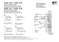
Smoke control unit Type: WSC 308 01 - WindowMaster
Smoke control unit Type: WSC 308 01 - WindowMaster
Smoke control unit Type: WSC 308 01 - WindowMaster

Create successful ePaper yourself
Turn your PDF publications into a flip-book with our unique Google optimized e-Paper software.
Operation Manual / Technical information<br />
<strong>Smoke</strong> <strong>control</strong> <strong>unit</strong><br />
<strong>Type</strong>:<br />
<strong>WSC</strong> <strong>308</strong> <strong>01</strong><br />
Table of contents:<br />
Safety information<br />
Operating elements / diagnosis LED's / fuse review<br />
Technical function description<br />
Technical data<br />
Installation and assembly<br />
Cable lengths table<br />
Cable plan<br />
Wiring diagram<br />
Start-up and test run<br />
CH: <strong>WindowMaster</strong> AG<br />
+41 (0) 62 289 22 22<br />
D: <strong>WindowMaster</strong> GmbH<br />
+49 (0) 5731 7583-0<br />
GB: <strong>WindowMaster</strong> Control Systems Limited<br />
+44 (0) 1536 510 990<br />
Head office:<br />
<strong>WindowMaster</strong> A/S<br />
Skelstedet 13<br />
2950 Vedbæk<br />
Denmark<br />
+45 45 67 03 00<br />
www.<strong>WindowMaster</strong>.com<br />
WMa 200546-0407 ©2005, 2007 <strong>WindowMaster</strong> A/S ®Windowmaster is a registered trademark used under licence by <strong>WindowMaster</strong> Group
Safety information <strong>WSC</strong> <strong>308</strong> <strong>01</strong><br />
Attention!<br />
Adherence to the following information is mandatory:<br />
Only allow correspondingly trained, qualified<br />
and skilled personnel to carry out installation work.<br />
Reliable operation and the avoidance of<br />
damage and hazards is only guaranteed if<br />
installation and settings are carried out carefully<br />
in accordance with these instructions.<br />
Check the technical data on the system plate.<br />
Hazards to persons ensuing from flaps and<br />
wings operated by electric motors.<br />
The forces occurring in the automatic mode can<br />
be such that parts of the body could get crushed.<br />
When opened, actuators could protrude into the<br />
room.<br />
For this reason, measures have to be taken<br />
prior to starting up the actuators which exclude<br />
the danger of injury.<br />
With wings tilting inwards or outwards, the wing<br />
must be protected from hinging down once the<br />
actuator is unhooked (e.g. for window cleaning).<br />
For safety reasons we recommend the use of<br />
catching shears.<br />
In the event that wings or flaps are subjected to<br />
high wind loads, we recommend to connect the<br />
central <strong>control</strong> <strong>unit</strong> to a wind detector which will<br />
automatically close the flaps.<br />
The fastening methods are exclusively intended<br />
for the intended use for which they are designed<br />
The manufacturer does not assume any liability<br />
for possible damage resulting from inappropriate<br />
use.<br />
230V AC dangerous voltage<br />
Can cause death, severe injury or considerable<br />
damage to assets.<br />
The connection of the <strong>control</strong> system is reserved<br />
for qualified personnel.<br />
Disconnect all poles of the <strong>unit</strong> from the supply<br />
voltage prior to opening, installation or<br />
assembling. Adhere to the VDE regulations.<br />
Field of application<br />
The central <strong>control</strong> system is exclusively designed<br />
for the automatic closing of smoke extraction<br />
systems, windows, flaps or doors.<br />
Always check that your system meets the valid<br />
regulations.<br />
Pay particular attention to the opening cross section,<br />
the opening time and opening speed. The cable cross<br />
sections depend on the cable length and current<br />
consumption (amperage).<br />
Maintenance work<br />
Where devices are used in smoke and heat<br />
extraction systems, ensure that they are checked,<br />
maintained and, if necessary, repaired at least once<br />
per year.<br />
Remove all soiling from the devices,<br />
check the fastening and clamping screws for firm<br />
seating. Trial run the entire system.<br />
Defective devices may only be repaired in our factory.<br />
Only use original spare parts.<br />
The supplied accumulators are subject to regular<br />
checks and must be replaced every 4 years.<br />
Cable routing and electrical connection<br />
Fuse the 230V AC power supply cable separately on<br />
site. Leave the insulation of the power supply<br />
cable in place up to the mains terminal.<br />
Adhere to the DIN and VDE regulations (Germany)<br />
or equivalent in your country.<br />
Establish the cable types, if necessary, with the local<br />
approval bodies or the fire protection authority.<br />
Do not conceal flexible cables. Junction box<br />
must be accessible for maintenance purposes.<br />
Disconnect all poles of the mains voltage and the<br />
accumulators prior to starting maintenance work or<br />
making changes to the system.<br />
Secure the system to prevent unintentional switching<br />
on again.<br />
Design cable types, lengths and cross sections in<br />
accordance with the technical information.<br />
Route all low voltage cables (24V DC) separate from<br />
the power current cables.<br />
Manufacturer's declaration<br />
The devices have been inspected and manufactured<br />
in accordance with the European directives.<br />
A corresponding manufacturer's declaration is<br />
available.<br />
You are only authorised to use the devices if a<br />
conformity declaration is issued for the entire system.<br />
<strong>Smoke</strong> <strong>control</strong> <strong>unit</strong> – <strong>Type</strong>: <strong>WSC</strong> <strong>308</strong> <strong>01</strong> 2
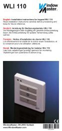
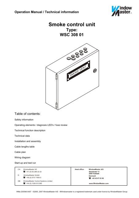
Operating elements, diagnosis LED's, fuse review and terminals<br />
<strong>Smoke</strong> <strong>control</strong> <strong>unit</strong> <strong>WSC</strong> <strong>308</strong> <strong>01</strong><br />
- +<br />
(SHE CLOSED)<br />
Reset<br />
Diagnosis LEDs<br />
Dead man´s <strong>control</strong><br />
DIP switches<br />
Trip following a malfunction<br />
Wind/<br />
Rain<br />
Vent<br />
button<br />
SHE<br />
switch<br />
SHE<br />
display<br />
Wind/rain<br />
PTC<br />
250mA<br />
Vent. OPEN<br />
display<br />
PTC<br />
120mA<br />
Manual<br />
detector<br />
PTC<br />
250mA<br />
3 min. alarm relay timer<br />
DIP switches<br />
Activate maintenance<br />
Temperature fuse 72 °C<br />
Autom.<br />
detector<br />
PTC<br />
120mA<br />
Battery<br />
M800mA<br />
Motor<br />
T 8A<br />
U<br />
Netz<br />
LED<br />
PTC = overload protection, ist temperature<br />
rises to >80° C following a short circuit !<br />
Mains<br />
Operating<br />
Accu<br />
Motor<br />
SHE switch<br />
<strong>Smoke</strong> det.<br />
<strong>Smoke</strong><br />
det.<br />
Alarm<br />
Mains<br />
T 1,6A<br />
External<br />
voltage<br />
PTC<br />
250mA<br />
Primary transformer<br />
Secondary transformer<br />
<strong>Smoke</strong> <strong>control</strong> <strong>unit</strong> – <strong>Type</strong>: <strong>WSC</strong> <strong>308</strong> <strong>01</strong> 3
Technical function description <strong>WSC</strong> <strong>308</strong> <strong>01</strong><br />
<strong>Smoke</strong> and heat extraction system alarm trip:<br />
Break glass <strong>unit</strong>::<br />
Break the glass in the break glass <strong>unit</strong>! Press the red button. The smoke extraction opens.<br />
An acoustic alarm signal sounds (continuous sound) in the break glass <strong>unit</strong>.<br />
All ventilation functions are out of operation.<br />
Display: The red alarm LED in the smoke <strong>control</strong> <strong>unit</strong> and the red LED in the break glass <strong>unit</strong> are lit.<br />
<strong>Smoke</strong> detector:<br />
If smoke develops, the smoke extraction system automatically opens.<br />
An acoustic alarm signal sounds (continuous sound) in the break glass <strong>unit</strong>.<br />
All ventilation functions are out of operation.<br />
Display: The red alarm LED in the smoke <strong>control</strong> <strong>unit</strong>, the red LED in the break glass <strong>unit</strong>, and the red LED at<br />
the tripped automatic detector are lit.<br />
Resetting a tripped smoke <strong>control</strong> <strong>unit</strong>:<br />
Press the „CLOSE button“ in the break glass <strong>unit</strong> or the „Reset button” in the smoke <strong>control</strong> <strong>unit</strong>.<br />
The acoustic alarm signal in the break glass <strong>unit</strong> stops sounding.<br />
The ventilation functions are operational again once the smoke extraction system has closed.<br />
(Prior to resetting, blow out or replace the detector after it was tripped by an automatic detector).<br />
Display: The red alarm LED in the smoke <strong>control</strong> <strong>unit</strong>, the red LED in the break glass <strong>unit</strong>, and the red LED at<br />
the tripped automatic detector extinguish.<br />
Tripping caused by high temperature:<br />
The function is activated, SW 2/1 =ON.<br />
The smoke <strong>control</strong> system automatically trips if the temperature inside the smoke <strong>control</strong> <strong>unit</strong> exceeds 70°C.<br />
An acoustic alarm signal sounds (continuous sound) in the break glass <strong>unit</strong>.<br />
Display: The red alarm LED in the smoke <strong>control</strong> <strong>unit</strong> and the red LED in the break glass <strong>unit</strong> are lit.<br />
The yellow malfunction LED in the break glass <strong>unit</strong> flashes. The green operating LED's extinguish.<br />
Resetting a trip caused by high temperature:<br />
The smoke extraction system can be closed again by pressing the „Reset button“ in the smoke <strong>control</strong> <strong>unit</strong> or<br />
the „CLOSE button“ in the break glass <strong>unit</strong>.<br />
After operating the CLOSE function, an acoustic pulse tone sounds, and the flashing malfunction LED is only<br />
displayed in the break glass <strong>unit</strong>.<br />
Note:<br />
The built-in thermal switch will then be irreversibly destroyed. The smoke <strong>control</strong> <strong>unit</strong> has to be returned for<br />
checking.<br />
Alarm trip caused by a malfunction signal:<br />
When this function is activated (SW2/1 = ON), the smoke <strong>control</strong> <strong>unit</strong> will trip in the event of a motor, smoke<br />
detector or break glass <strong>unit</strong> circuit malfunction. An acoustic alarm signal sounds (continuous sound) in the<br />
break glass <strong>unit</strong>.<br />
No trip occurs as a result of a malfunction in the mains or battery circuit.<br />
Display: The red alarm LED in the smoke <strong>control</strong> <strong>unit</strong> and the red LED in the break glass <strong>unit</strong> are lit.<br />
The yellow malfunction LED in the break glass <strong>unit</strong> and the corresponding yellow malfunction<br />
LED in the smoke <strong>control</strong> <strong>unit</strong> flash.<br />
Option: External signalling of the alarm or malfunction signal<br />
It is possible to send an alarm or malfunction signal potential free, by plugging in the alarm/malfunction<br />
signalling module.<br />
Cascading smoke <strong>control</strong> <strong>unit</strong>s:<br />
The smoke <strong>control</strong> <strong>unit</strong>s can be cascaded by a monitored 2 wire connection from the alarm module of the<br />
master smoke <strong>control</strong> <strong>unit</strong> to the smoke detector input of the slave central panel.<br />
A malfunction in the cascaded smoke <strong>control</strong> <strong>unit</strong>s is detected via the 2 wire BUS cable. The malfunction is<br />
only displayed in the corresponding smoke <strong>control</strong> <strong>unit</strong> and in the break glass <strong>unit</strong> connected to the master<br />
smoke <strong>control</strong> <strong>unit</strong>.<br />
<strong>Smoke</strong> <strong>control</strong> <strong>unit</strong> – <strong>Type</strong>: <strong>WSC</strong> <strong>308</strong> <strong>01</strong> 4
Technical function description <strong>WSC</strong> <strong>308</strong> <strong>01</strong><br />
Ventilation functions:<br />
Ventilation OPEN:<br />
With the dead man's circuit activated (SW2/2 = ON), the actuators only move open for as long as the OPEN<br />
button of the ventilation button is kept pressed.<br />
If no dead man's function is activated (SW2/2 = OFF), the actuators open after pressing the OPEN button<br />
(self hold).<br />
Display: The ventilation open LED in the ventilation button is lit (only with LED integrated in the button).<br />
Ventilation stop:<br />
The actuators stop when both buttons are pressed.<br />
Display: The ventilation open LED in the ventilation button remains lit (only with LED integrated in the button).<br />
Ventilation closed:<br />
The actuators close after pressing the CLOSED button.<br />
Display: The ventilation open LED in the ventilation button has extinguished (only with LED integrated in the<br />
button).<br />
Option: Ventilation time module<br />
Time setting between 1 and 30 min. Once this time has elapsed, the actuators close after ventilation „OPEN“<br />
or ventilation „STOP“. This function is not operative if the setting potentiometer is on the right-hand stop.<br />
Wind/rain CLOSE:<br />
The actuators close when the wind/rain sensor has tripped (potential free contact in the sensor switches). The<br />
ventilation functions are out of operation as long as a tripped situation is pending.<br />
Option: Transmission of the wind/rain signal<br />
The trip signal of the wind/rain sensor can be transmitted potential free to the next smoke <strong>control</strong> <strong>unit</strong><br />
by plugging in the wind/rain relaying module.<br />
Note: All ventilation functions are locked in the event of a power failure or when an alarm is triggered!<br />
General information:<br />
CLOSE after a power failure:<br />
Opened actuators will automatically close via the ventilation system 2 minutes after a power failure.<br />
The motor voltage will be deactivated after another 2 minutes.<br />
In the event the smoke <strong>control</strong> system trips, this function will be deactivated.<br />
EMC protection:<br />
All inputs and outputs are protected from coupled in interferences.<br />
Short-circuit protection:<br />
All outputs are protected against short-circuit and overload.<br />
Maintenance:<br />
<strong>Smoke</strong> <strong>control</strong> systems must be maintained by the builder at least once per year.<br />
The maintenance and check of the system must be documented in a test placard in the smoke <strong>control</strong> <strong>unit</strong> as<br />
well as in a logbook.<br />
<strong>Smoke</strong> <strong>control</strong> <strong>unit</strong> – <strong>Type</strong>: <strong>WSC</strong> <strong>308</strong> <strong>01</strong> 5
Technical function description <strong>WSC</strong> <strong>308</strong> <strong>01</strong><br />
Optional sheet for CLOSE signal from ASV<br />
The ASV-CLOSE function is an optional function that must be specially made in the production by using<br />
special software.<br />
ASV CLOSE:<br />
When ASV CLOSE is tripped, all actuators automatically „CLOSE“.<br />
An acoustic alarm signal sounds (continuous sound) in the break glass <strong>unit</strong>.<br />
All ventilation functions are out of operation.<br />
Display: The red alarm LED in the smoke <strong>control</strong> <strong>unit</strong> and the red LED in the break glass <strong>unit</strong> are lit.<br />
An alarm in the break glass <strong>unit</strong> (actuators “OPEN“ ) has priority over an ASV CLOSE signal.<br />
<strong>Smoke</strong> <strong>control</strong> <strong>unit</strong> – <strong>Type</strong>: <strong>WSC</strong> <strong>308</strong> <strong>01</strong> 6
Technical data, <strong>Smoke</strong> central <strong>unit</strong> <strong>Type</strong> <strong>WSC</strong> <strong>308</strong> <strong>01</strong><br />
Supply voltage / mains connection 230V AC / 50Hz ( +10% / -15% )<br />
Safety transformer according to EN 61558<br />
Mains amperage<br />
200VA<br />
Rated voltage (at 230V mains voltage)<br />
24V DC , load dependent<br />
Emergency power supply batteries<br />
2x 12V / 7Ah 4 year operating time<br />
Charging <strong>unit</strong>: Charging voltage 27.5V 28V<br />
Charging current<br />
700mA, current limited<br />
Operating duration (emergency power supply )<br />
Current load of the actuators<br />
72 hours if batteries are fully charged<br />
8A max.<br />
Switch-on duration 20%<br />
Review of fuses<br />
<strong>Type</strong> of connection to external<br />
Cable monitoring<br />
Message Alarm trip / malfunction<br />
Environment class<br />
Housing<br />
Mains 1.6A slow-blow<br />
Motor 8 A slow-blow<br />
Battery 800mA medium slow-blow<br />
Mains screw terminal / plug/screw terminals / 0.5-2.5sqmm<br />
Motor screw terminal 0.5-10sqmm<br />
automatic detectors (detector circuit with active end<br />
module), break glass <strong>unit</strong> (detector circuit with end resistor,<br />
actuators (with motor end module), batteries (cyclic<br />
measurement)<br />
optically alternating or steady signals by LED's<br />
Operating and alarm tripping = steady signal. Malfunction<br />
ofbattery, motor, break glass <strong>unit</strong> and smoke detector in the<br />
event of an interruption = alternating, in the event of a short<br />
circuit = steady signal<br />
III according to VdS 2581 / 2593 (-5°C to +40°C)<br />
Sheet steel housing, type KL-40/30-S103<br />
surface-mounted<br />
Protection class I<br />
Dimensions WxHxD 400x300x120mm<br />
Protection type according to DIN EN60529 IP 54<br />
Weight Central <strong>unit</strong> without batteries approx. 8.8 kg<br />
with batteries approx. 13.4kg<br />
Colour RAL 7035<br />
<strong>Smoke</strong> <strong>control</strong> <strong>unit</strong> – <strong>Type</strong>: <strong>WSC</strong> <strong>308</strong> <strong>01</strong> 7
Technical data, <strong>Smoke</strong> central <strong>unit</strong> <strong>Type</strong> <strong>WSC</strong> <strong>308</strong> <strong>01</strong><br />
Connection possibilities:<br />
1) Motors up to 8A.<br />
2) <strong>Smoke</strong> detectors, differential heat detectors and/or maximum heat detectors, multi-sensor smoke<br />
detectors (smoke/heat combination detectors), up to 15 <strong>unit</strong>s.<br />
3) Break glass <strong>unit</strong>s (primary), up to 6 <strong>unit</strong>s (max. current load of the alarm display = 250mA).<br />
4) Break glass <strong>unit</strong>s (secondary), up to 15.<br />
5) Ventilation buttons with ‚open' indicator, up to 15, any number without ‚open' indicator (max.<br />
current load = 120mA).<br />
6) Wind/rain detectors with potential free N/O contact (max. current load of the detector = 250mA).<br />
7) ASC CLOSE function at the smoke detector input (insert ASV module).<br />
Operating/<strong>control</strong> elements:<br />
The reset button on the <strong>control</strong> PCB is used to reset a tripped smoke ventilation system and to close the<br />
actuators.<br />
Setting possibilities via slide switch SW1:<br />
SW 1/1 = ON<br />
SW 1/1 = OFF<br />
Maintenance <strong>control</strong> is activated.<br />
Maintenance <strong>control</strong> is not activated. Only a coded deactivation is possible following an<br />
activation!<br />
As a <strong>control</strong> of the activation, the operating LED flashes for 10 sec. If SW1/1 is switched back to OFF again<br />
within this time, the activation process is deleted.<br />
The maintenance <strong>control</strong> is triggered after the elapse of a 12 month time period. The yellow malfunction LED in<br />
the break glass <strong>unit</strong> (primary) is lit, and a permanent acoustic alarm signal sounds. Also the green operating<br />
LED is still lit to indicate the absence of a fault. A malfunction message has priority.<br />
SW 1/2 = ON The transmission of the alarm message (alarm malfunction module 1) is interrupted after 3<br />
minutes.<br />
SW 1/2 = OFF The alarm message (alarm malfunction module 1) is transmitted for as long as an alarm is<br />
tripped.<br />
Setting possibilities via slide switch SW2:<br />
SW 2/1 = ON<br />
SW 2/1 = OFF<br />
SW 2/2 = ON<br />
SW 2/2 = OFF<br />
The smoke <strong>control</strong> system trips following a malfunction message from the motor, smoke<br />
detector, SHE switch circuit, over-temperature<br />
The smoke <strong>control</strong> system does not trip following a malfunction message. The malfunction<br />
message is only displayed by LED`s.<br />
The actuators only move OPEN for as long as the ventilation button is pressed (dead man<br />
<strong>control</strong>).<br />
The actuators move OPEN as soon as the ventilation button is pressed (self-hold).<br />
MALFUNCTION REMEDY:<br />
Diagnosis / monitoring in the smoke <strong>control</strong> <strong>unit</strong>:<br />
LED's on the PCB's Function OK Malfunction Diagnosis<br />
Mains (green) lit off Check mains voltage and mains fuse<br />
Operation (green) lit off<br />
at any malfunction<br />
Check all functions Temp.<br />
Check temperature fuse for 0 Ohm<br />
<strong>Smoke</strong> detector (yellow)) off flashes when interrupted,<br />
is lit after a short circuit<br />
Check wiring and the active end<br />
module<br />
Break glass <strong>unit</strong> (yellow) off flashes when interrupted,<br />
is lit after a short circuit<br />
Check wiring and jumper J1 in the<br />
last or only break glass <strong>unit</strong><br />
Motor Circuit (yellow) off flashes when interrupted,<br />
after approx. 8 s<br />
Check motor end module and<br />
the motor fuse<br />
Battery/load <strong>control</strong><br />
(yellow)<br />
off see diagnosis battery see diagnosis battery<br />
<strong>Smoke</strong> <strong>control</strong> <strong>unit</strong> – <strong>Type</strong>: <strong>WSC</strong> <strong>308</strong> <strong>01</strong> 8
Technical data, <strong>Smoke</strong> <strong>control</strong> <strong>unit</strong> <strong>Type</strong> <strong>WSC</strong> <strong>308</strong> <strong>01</strong><br />
Diagnosis / battery monitoring:<br />
Battery charge:<br />
Charging voltage 27.5V to 28V. Charging current limited to approx. 700mA.<br />
Short-circuit monitoring of the connection cables, charging voltage disconnected in the event of a short-circuit.<br />
Malfunction Function Diagnosis<br />
Yellow battery LED flashes Mains failure Check mains fuse<br />
Yellow battery LED is lit<br />
No battery connected or battery<br />
voltage below 19V<br />
Check battery, battery voltage and<br />
battery fuse<br />
Note: The battery malfunction indicator can have a time delay of approx. 8 s.<br />
Note:<br />
Replace the emergency power batteries every 4 years!<br />
Optional plug-in modules:<br />
Multi-input malfunction warning module (WSA 3<strong>01</strong>) – Model 1:<br />
Multi-input malfunction warning:<br />
1 x change-over contact (max. load: 60V, 1A) with 3 pole connection terminal for potential free transmission<br />
to the BMS / panel etc.<br />
2 pole connection terminal for 2 wire BUS cable for the feedback of malfunctions in cascaded smoke <strong>control</strong><br />
<strong>unit</strong>s to the break glass <strong>unit</strong> connected to the master smoke <strong>control</strong> <strong>unit</strong>.<br />
Alarm message:<br />
1 x change-over contact (max. load: 60V, 1A) with 3 pole connection terminal for potential free transmission<br />
to BMS / panel etc., or as monitored 2 wire alarm cable for cascading smoke <strong>control</strong> <strong>unit</strong>s.<br />
Jumper plugged in J1 = Only for the alarm transmission to the next smoke <strong>control</strong> panel <strong>unit</strong> (cascading).<br />
Jumper plugged in J2 = pot.-free alarm contact (factory setting).<br />
Wind/rain relaying module (WSA 302) – Module 2:<br />
1 x change-over contact (max. load: 60V, 1A) with 3 pole connection terminal for potential free transmission<br />
of the wind/rain trip.<br />
Ventilation time module (WSA 303) – Model 3:<br />
Automatic closing in the ventilation mode according to preselected time (1 min. to 30 min.) after ventilation<br />
OPEN was actuated.<br />
Installation information:<br />
Fit the break glass <strong>unit</strong>s at a height of approx. 1.40 m of FF top edge.<br />
<strong>Smoke</strong> <strong>control</strong> <strong>unit</strong> – <strong>Type</strong>: <strong>WSC</strong> <strong>308</strong> <strong>01</strong> 9
Installation und Montage <strong>WSC</strong> <strong>308</strong> <strong>01</strong><br />
Cable routing<br />
Please note the safety information contained in this operating manual.<br />
For the type of cables and routing, please refer to Electrical cables.<br />
Do not reduce the cable cross sections specified in the cable lengths table.<br />
All cables of the smoke <strong>control</strong> <strong>unit</strong> (except the mains supply cable) carry 24V DC and have to be routed<br />
separate from the mains supply cable.<br />
Adhere to the pertinent VDE regulations when routing the cables.<br />
Do not use the green/yellow conductor.<br />
Ensure that the mains cable can be switched via an external or customer-supplied two-pole switch element or<br />
a switch element <strong>control</strong>ling all poles.<br />
<strong>Smoke</strong> <strong>control</strong> <strong>unit</strong> installation<br />
Note the smoke <strong>control</strong> <strong>unit</strong> has to be installed in a dry room.<br />
Surface mounted housing<br />
Refer to the sketch below for the installation position<br />
Open the smoke <strong>control</strong> <strong>unit</strong> and affix by means of the 4 holes in the building structure. Ensure that suitable<br />
fastening material is available.<br />
Note!<br />
Place sealing washers (plastic or similar) between the housing wall and the fastening screws (IP 54 !).<br />
Installation of the Break glass <strong>unit</strong>, ventilation buttons and detectors<br />
Ensure that the Break glass <strong>unit</strong> and the ventilation buttons are visible and well accessible. Do not fit behind<br />
protruding walls, door panels or hidden by the building structure.<br />
Note: Installation height of the Break glass <strong>unit</strong> = 1.4 m above floor top edge.<br />
Install the automatic detectors in accordance with the enclosed operating manuals.<br />
Installation<br />
Lead the connection cables into the housing of the smoke <strong>control</strong> <strong>unit</strong> from above.<br />
All connection terminals (except the mains terminals and the motor terminals) are pluggable.<br />
Connect the connection cables in accordance with the terminal plan. Ensure that the connections are made<br />
correctly.<br />
Incorrect connection, number and colour errors could lead to malfunctions of the smoke <strong>control</strong> <strong>unit</strong> or of the<br />
external elements.<br />
<strong>Smoke</strong> <strong>control</strong> <strong>unit</strong> – <strong>Type</strong>: <strong>WSC</strong> <strong>308</strong> <strong>01</strong> 10
Electrical cables<br />
Ensure that the electrical cables are always routed according to the valid national and local regulations of the individual<br />
country.<br />
Maintaining the cable functions<br />
The sample cable system directive (MLAR) in its current version is decisive for the type of cables and their corresponding<br />
way of routing. In most of the German provinces, MLAR has been introduced as Technical Construction Regulation.<br />
Various revisions of the MLAR as Technical Construction Regulation are valid in the individual provinces. Due to the fact<br />
that the requirements with regard to the conductors for smoke <strong>control</strong> systems contained in the individual versions differ<br />
considerably, different conductor requirements result for the individual provinces. MLAR is based on the state-of-the-art of<br />
the year 2000 (Revision: 06/20<strong>01</strong>). In this directive, for the first time a differentiation is made between machine operated<br />
and natural smoke ventilation systems. For natural smoke extraction systems it is sufficient to maintain the function<br />
according to classification E30. These cables must be checked and approved in accordance with DIN 4102 Part 12. Route<br />
the cables in conformity with the instructions of the cable manufacturers using the corresponding fastening materials.<br />
The maintenance of the function for the smoke ventilation cables is not required if all cable paths are monitored by the<br />
smoke detector and when the smoke and heat detection system opens as a result of the automatic detector tripping.<br />
Concealed installation is not an approved type of installation to maintain the function in accordance with DIN 4102 Part 12.<br />
The function is also only securely maintained by cables of class E30, or the room is monitored by smoke detectors.<br />
The cable network for smoke ventilation systems („Cable system“) ends at the interface (junction box) for the actuator!<br />
The flexible, heat resistant connection cable of the smoke ventilation system actuator is part of the system component<br />
‚electric motor actuation' and does not belong to the electrical installation!<br />
We recommend in all cases to discuss the type of cable routing with the competent fire fighting authorities.<br />
Independent of the fact whether or not the respective MLAR is introduced in the corresponding province as<br />
Technical Building Regulation, we recommend to point out the technical possibilities and the state-of-the-art of<br />
MLAR 2000.<br />
Cable length table<br />
For determining the maximum permissible cable lengths between the smoke <strong>control</strong> <strong>unit</strong> and the actuators, taking into<br />
account the specified cables cross sections, please refer to the following table:<br />
Maximum motor current: 8A Note: Be aware of the overall capacity/rating of the smoke <strong>control</strong> <strong>unit</strong>!<br />
Maximum cable length: (always routed from the central <strong>control</strong> panel to the last connection socket)<br />
Actuating current: Sum of all motor currents per group module<br />
Note:<br />
Do not use the green/yellow wire!<br />
Per motor supply line, 3 wires are required (2 wires current carrying /1 wire for monitoring)<br />
Cross section 3 wire 5 wire 3 wire 5 wire 3 wire 3 wire<br />
1,5 mm² 1,5 mm² 2,5 mm² 2,5 mm² 4 mm² 6 mm²<br />
Actuator current in A (2 parallel wires) (2 parallel wires)<br />
1 84,00 m 168,00 m 140,00 m 280,00 m 224,00 m 336,00 m<br />
2 42,00 m 84,00 m 70,00 m 140,00 m 112,00 m 168,00 m<br />
3 28,00 m 56,00 m 46,67 m 93,33 m 74,67 m 112,00 m<br />
4 21,00 m 42,00 m 35,00 m 70,00 m 56,00 m 84,00 m<br />
5 16,80 m 33,60 m 28,00 m 56,00 m 44,80 m 67,20 m<br />
6 14,00 m 28,00 m 23,33 m 46,67 m 37,33 m 56,00 m<br />
7 12,00 m 24,00 m 20,00 m 40,00 m 32,00 m 48,00 m<br />
8 10,50 m 21,00 m 17,50 m 35,00 m 28,00 m 42,00 m<br />
(The information is valid for ambient temperatures of 25°C)<br />
Formula for the calculation of the maximum cable length<br />
Maximum permissible voltage drop in the cable UL : 2 Volt<br />
max. cable length =<br />
permissible voltage drop (UL) x conductivity of copper (56) x cable cross section (A)<br />
max. actuator current total (I) in amps x 2<br />
Permissible cable length for the break glass <strong>unit</strong> supply cable when using......4x2x0.8mm: up to 200m<br />
The motor connection cable length to the junction box (or <strong>control</strong> module) must not exceed 10 m.<br />
<strong>Smoke</strong> <strong>control</strong> <strong>unit</strong> – <strong>Type</strong>: <strong>WSC</strong> <strong>308</strong> <strong>01</strong> 11
Cable plan<br />
<strong>Smoke</strong> <strong>control</strong> <strong>unit</strong> – <strong>Type</strong>: <strong>WSC</strong> <strong>308</strong> <strong>01</strong> 12
Standard wiring diagram<br />
<strong>Smoke</strong> <strong>control</strong> <strong>unit</strong> – <strong>Type</strong>: <strong>WSC</strong> <strong>308</strong> <strong>01</strong> 13
Various wiring diagrams<br />
<strong>Smoke</strong> <strong>control</strong> <strong>unit</strong> – <strong>Type</strong>: <strong>WSC</strong> <strong>308</strong> <strong>01</strong> 14
Various wiring diagrams<br />
<strong>Smoke</strong> <strong>control</strong> <strong>unit</strong> – <strong>Type</strong>: <strong>WSC</strong> <strong>308</strong> <strong>01</strong> 15
Commissioning <strong>WSC</strong> <strong>308</strong> <strong>01</strong><br />
When error message occur, please refer to chapter Operating elements/LED diagnosis.<br />
An acoustic message only occurs in the break glass <strong>unit</strong> (primary) with the door closed or the door<br />
contact switch pressed!<br />
1) The smoke <strong>control</strong> <strong>unit</strong> is completely installed, without the operating voltage applied<br />
a) Check all mechanical and electrical components for damage.<br />
b) Check the DIP slide switches in the smoke <strong>control</strong> <strong>unit</strong> for their correct (required) position.<br />
c) Check all screw and plug connections for tightness and/or firm seating.<br />
d) Check that all external components are installed.<br />
Actuators:<br />
Is the final module at the last or only actuator inserted<br />
Automatic detectors: Is the active end module at the last or only detector inserted<br />
Manual detectors: Is the jumper only inserted in the last or only operating panel<br />
2) With mains voltage, without battery<br />
Adhere to the VDE regulations! Externally disconnect the mains voltage.<br />
a) Connect the mains cables and reapply the mains voltage.<br />
b) The mains LED is ON, the operating LED is OFF, the battery LED is ON. The malfunction signal at the<br />
break glass <strong>unit</strong>s is ON.<br />
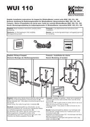
3) With mains voltage, with battery<br />
a) Remove the protection film from one face of the supplied foam rubber. Glue each foam rubber to the<br />
bottom side of the batteries. Connect the batteries to the black battery bridge according to the wiring<br />
diagram, then connect the red and the blue connection cable to the red and the black flat plug.<br />
Remove the bottom protection film of the foam rubber and insert the batteries in the smoke <strong>control</strong> <strong>unit</strong><br />
according to figure 1 (symmetrically, with an approx. 3 mm spacing from the housing edge), and firmly<br />
press down to the housing bottom!<br />
b) Plug the red connection cable to the + and the blue connection to the flat plug of the smoke <strong>control</strong><br />
<strong>unit</strong>. Note: Check correct polarity!<br />
c) The operating LED is ON, the battery LED is OFF. The malfunction signal at the break glass <strong>unit</strong>s is<br />
OFF.<br />
4) Ventilation button<br />
a) Closely observe the actuators during opening and closing. They must not be impaired in any<br />
position by the building structure. Also the motor connection cables must not be subject to<br />
pulling or crushing.<br />
b) Briefly actuate the Open button to have the actuators move open up to the final position. With the<br />
SW2/2 =ON (hold-to-run) setting, the actuators only move as long as the button is pressed. The OPEN<br />
display (if existing) in the button is ON.<br />
c) Briefly actuate the CLOSED button, the actuators close. The Open display is OFF.<br />
d) Press both buttons simultaneously while running, this corresponds to stop. The ventilation Open<br />
display is ON, the actuators stop.<br />
e) Briefly press the Close button again, the actuators fully close, the Open display is OFF.<br />
5) Break glass <strong>unit</strong><br />
a) Open the door and press the red Open button. The actuators move open through to the end position.<br />
The red alarm LED (also in the smoke <strong>control</strong> <strong>unit</strong>) is ON, at the same time a permanent acoustic<br />
signal sounds (door contact pressed!).<br />
b) While running, press the Close button at the ventilation button, then press both buttons, the actuators<br />
must neither close nor stop!<br />
c) Press the reset/Closed button in the break glass <strong>unit</strong>. The actuators close through to the end position.<br />
The ventilation function is released again. The red alarm LED (also in the smoke <strong>control</strong> <strong>unit</strong>) and the<br />
signal generator are OFF.<br />
6) Break glass <strong>unit</strong> (secondary)<br />
a) Check as described under 5). “Operation”, “Malfunction” and the acoustic signal are missing!<br />
<strong>Smoke</strong> <strong>control</strong> <strong>unit</strong> – <strong>Type</strong>: <strong>WSC</strong> <strong>308</strong> <strong>01</strong> 16
Commissioning <strong>WSC</strong> <strong>308</strong> <strong>01</strong><br />
7) Automatic detectors<br />
a) Spray test aerosol on the detectors.<br />
b) The actuators move open through to the end position. The red LED in the detector, the red alarm LED<br />
(also in the smoke <strong>control</strong> <strong>unit</strong>) and the permanent acoustic signal in the break glass <strong>unit</strong> are ON.<br />
c) While running, press the Close button at the ventilation button, then press both buttons, the actuators<br />
must neither close nor stop!<br />
d) Press the reset/Close button in the break glass <strong>unit</strong>. The actuators close through to the end position.<br />
The ventilation function is released again. The red alarm LED (also in the smoke <strong>control</strong> <strong>unit</strong>) and the<br />
signal generator are OFF.<br />
8) Emergency power supply test<br />
a) Remove the mains fuse from the smoke <strong>control</strong> <strong>unit</strong>. Adhere to the VDE regulations!<br />
b) The green mains and operating LED's are OFF, the yellow battery LED is flashing (smoke <strong>control</strong> <strong>unit</strong><br />
in the battery mode). The malfunction signal at the break glass <strong>unit</strong>s is ON.<br />
c) The ventilation buttons are deactivated.<br />
d) If the actuators were open, they will automatically close after 2 minutes.<br />
e) Test the smoke trip and reset/close as described under 5).<br />
f) Refit the mains fuse.<br />
g) The green mains and operating LED's are ON, the yellow battery LED is OFF. The malfunction signal<br />
at the break glass <strong>unit</strong>s is OFF.<br />
9) Activation of internal check<br />
a) Move the DIP switch SW1/1 to ON<br />
b) As a <strong>control</strong> of the activation the operating LED flashes for 10 sec.<br />
c) If SW1/1 is switched back to OFF again within this time, the activation process is deleted.<br />
d) After 10 sec. is the operating LED continuously lit, and the internal check is activated.<br />
10) Wind/rain detector<br />
a) Open the actuators with the ventilation button.<br />
b) Wet the rain sensor, the actuators will fully close, the green wind/rain LED in the <strong>control</strong> centre is ON.<br />
c) While running, press the Open button at the ventilation button, then press both buttons, the actuators<br />
must neither open nor stop!<br />
d) The SHE trip has priority.<br />
When the start-up was successful, then close the doors of the break glass <strong>unit</strong>s and of the smoke <strong>control</strong> <strong>unit</strong>.<br />
If the start-up was unsuccessful (error with one of the test run processes), please refer to the chapter Function<br />
description and Operating elements / LED diagnosis. If necessary, check the wiring in accordance with the<br />
wiring diagram.<br />
<strong>Smoke</strong> <strong>control</strong> <strong>unit</strong> – <strong>Type</strong>: <strong>WSC</strong> <strong>308</strong> <strong>01</strong> 17