CAICE Attenuator
CAICE Attenuator
CAICE Attenuator

You also want an ePaper? Increase the reach of your titles
YUMPU automatically turns print PDFs into web optimized ePapers that Google loves.
Crosstalk Selection Guide<br />
Guide to Crosstalk Attenuation Selection<br />
The following guide is intended to provide a quick method for<br />
selection of crosstalk attenuators in a common ducted system or<br />
ceiling void return air path. For accurate selection, or where<br />
attenuators are intended for use in sensitive locations such as<br />
high acoustically rated partitions (typically in excess of Rw40),<br />
please refer to one of our acoustic engineers.<br />
When making selections for crosstalk attenuators, it is<br />
necessary to consider the following aspects:<br />
1. The level of speech reaching the receiving room:<br />
The source of crosstalk nuisance is assumed to be raised<br />
speech, for which the average sound pressure level (500-4kHz)<br />
is 70dB*.<br />
The room to room acoustic loss for a typical common ductwork<br />
system or via the ceiling void is approximately 7dB, therefore the<br />
average speech level within the receive room is taken to be<br />
70 - 7 = 63 dB.<br />
2. The noise criteria for the design of mechanical services<br />
in each space being considered:<br />
If crosstalk is being assessed between two adjacent room areas<br />
with different noise criteria, then the lowest criteria should be<br />
used.<br />
Subtract the required NR level from the received speech level to<br />
give the additional average insertion loss requirement.<br />
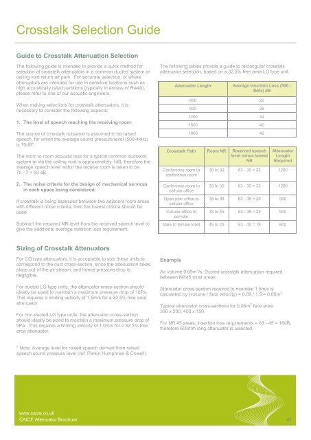
The following tables provide a guide to rectangular crosstalk<br />
attenuator selection, based on a 32.5% free area LG type unit.<br />
<strong>Attenuator</strong> Length Average Insertion Loss (500 -<br />
4kHz) dB<br />
Crosstalk Path Room NR Received speech<br />
level minus lowest<br />
NR<br />
Conference room to<br />
conference room<br />
Conference room to<br />
cellular office<br />
Open plan office to<br />
cellular office<br />
Cellular office to<br />
corridor<br />
600 22<br />
900 28<br />
1200 34<br />
1500 40<br />
1800 46<br />
<strong>Attenuator</strong><br />
Length<br />
Required<br />
30 to 30 63 - 30 = 33 1200<br />
30 to 35 63 - 30 = 33 1200<br />
35 to 38 63 - 35 = 28 900<br />
38 to 45 63 - 38 = 25 900<br />
Male to female toilet 45 to 45 63 - 45 = 18 600<br />
Sizing of Crosstalk <strong>Attenuator</strong>s<br />
For CG type attenuators, it is acceptable to size these units to<br />
correspond to the duct cross-section, since the attenuation takes<br />
place out of the air stream, and hence pressure drop is<br />
negligible.<br />
For ducted LG type units, the attenuator cross-section should<br />
ideally be sized to maintain a maximum pressure drop of 10Pa.<br />
This requires a limiting velocity of 1.5m/s for a 32.5% free area<br />
attenuator.<br />
For non-ducted LG type units, the attenuator cross-section<br />
should ideally be sized to maintain a maximum pressure drop of<br />
5Pa. This requires a limiting velocity of 1.0m/s for a 32.5% free<br />
area attenuator.<br />
Example<br />
Air volume 0.09m 3 /s. Ducted crosstalk attenuation required<br />
between NR45 toilet areas.<br />
<strong>Attenuator</strong> cross-section required to maintain 1.5m/s is<br />
calculated by (volume / face velocity) = 0.09 / 1.5 = 0.06m 2<br />
Typical attenuator cross-sections for 0.06m 2 face area:<br />
300 x 200, 400 x 150.<br />
For NR 45 areas, insertion loss requirements = 63 - 45 = 18dB,<br />
therefore 600mm long attenuator is selected.<br />
* Note: Average level for raised speech derived from raised<br />
speech sound pressure level (ref: Parkin Humphries & Cowell).<br />
www.caice.co.uk<br />
<strong>CAICE</strong> <strong>Attenuator</strong> Brochure<br />
41