A60 Marine Fire Smoke Damper - Actionair
A60 Marine Fire Smoke Damper - Actionair
A60 Marine Fire Smoke Damper - Actionair

Create successful ePaper yourself
Turn your PDF publications into a flip-book with our unique Google optimized e-Paper software.
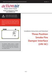
A-60 <strong>Marine</strong> <strong>Fire</strong> <strong>Damper</strong><br />
ATEX (Ex) Rated Actuator, Application and Wiring<br />
Atex (Ex) Rated Electrical Control Modes<br />
On-off 1-wire-spring return + Ex-i circuit<br />
Universal supply unit from 24 to 230V-AC/DC, 50/60 Hz.<br />
Supply On - <strong>Damper</strong> motors open.<br />
Supply Off - <strong>Damper</strong> springs closed.<br />
ExPro-TT Operates - <strong>Damper</strong> springs closed.<br />
20W (Maximum Blocking),<br />
16W (Heater).<br />
End Switches Rated at 250V 1.5 Amp (Maximum).<br />
To isolate from main power supply, the system must incorporate<br />
a device, which disconnects the phase conductors, with at least<br />
3mm contact gap.<br />
24...240 VAC/DC<br />
PE<br />
–<br />
~<br />
+<br />
~<br />
Attention<br />
If you use this<br />
type of wiring the<br />
heater does not<br />
work in case of<br />
open contact<br />
Integrated aux, switches<br />
max 24V/3A, 240V/0.25A<br />
min. 5V/10mA, switching<br />
at 5° and 85°.<br />
Supply at aux. switches<br />
must be the same like<br />
supply of the actuator<br />
< 5° < 85°<br />
Ex-i circuit for<br />
passive + potential<br />
free push button on<br />
site and safety<br />
temperature sensor<br />
(Type ExPro -TT<br />
accessories)<br />
ExPro -TT<br />
°C<br />
Push button<br />
A metre of halogen free, low smoke and fume electric cable is<br />
included with each control mode. The ExPro-TT is also prewired<br />
with a metre of halogen free low smoke and fume cable.<br />
1<br />
2<br />
Heater<br />
3 4 5 6 7 8 9 10 11 1 2<br />
Standard wiring = spring return in ~10 sec.<br />
Additional wiring terminal 5 = spring return in ~3 sec.<br />
PA<br />
Power input depending on supply voltage<br />
Power supply design<br />
The design of the on-site supply, depends on the selected motor<br />
running time and selected supply voltage. Accompanying values<br />
are “about values”, since there can be construction unit<br />
dispersions within electronics. The power consumption in the<br />
blocking position is run time independently with max 20W. The<br />
power consumption for the heater is approximately 16W. The<br />
heating is running only if the motor is in idle position. The initial<br />
starting supply voltage required by the actuators power supply<br />
unit is around 2.0A for about 1 sec. (Please consider this while<br />
calculating the cross section area of the supply line.)<br />
Rated current in acc. with motor running time<br />
Voltage Current 3/7,5s 15s 30s 60s 120s<br />
230V Irated 0.5A 0.3A 0.15A 0.10A 0.10A<br />
120V Irated 0.75A 0.4A 0.3A 0.25A 0.25A<br />
48V Irated 2.0A 0.5A 0.3A 0.2A 0.2A<br />
24V Irated 4.7A 1.45A 0.52A 0.4A 0.4A<br />
Dimensioning of the line cross section with 24 to<br />
48 Volt AC/DC supply voltages<br />
Dimensioning / Design of the supply line<br />
On long distances between supply and actuator, voltage drop<br />
occurs due to line resistances. On 24V AC/DC systems the<br />
actuator receives a low voltage and does not start. In order to<br />
prevent this, the cross section of the inlet line is to be<br />
designed/dimensioned accordingly. The accompanying formula<br />
allows the calculation of the required line cross section area and<br />
indicates the maximum length utilising an existing line.<br />
Alternatively the secondary voltage can be increased by selecting<br />
a transformer to overcome the loss.<br />
For calculation purposes, following characteristics are essential:<br />
UV = supply voltage in [V]<br />
A = line cross section in [mm 2 ]<br />
L = line length in [m]<br />
Factor 0.0714 = drive-specific factor<br />
[Vmm 2 /m] 9 based on the electrical conductivity of copper with a<br />
coefficient of 56/Wmm 2 )<br />
Uv [m]<br />
28<br />
27<br />
26<br />
25<br />
24<br />
23<br />
22<br />
21<br />
20<br />
.75 1mm2 1.5mm 2 2.0 2.5mm 2 4mm 2<br />
50 100 150 200 250 300 350 400 L [m]<br />
Example:<br />
24V power supply with diameter 1.5mm 2 = 126m<br />
Panel<br />
Voltage<br />
“Uv” [V]<br />
Formula for maximum cable<br />
length “L” at cable cross<br />
section “A”<br />
L = A(Uv-18V) 0.0714<br />
Example:<br />
A = 1.5mm 2 , Uv = 24V<br />
Length of cable L = 126m<br />
Line cross section “A” [mm 2 ]<br />
Lenght “L” [m]<br />
Terminal box<br />
Actuator<br />
Formula of needed cable<br />
cross section “A” at a cable<br />
length of “L”<br />
A = 0.0714 L(Uv-18V)<br />
Example:<br />
L = 250m, Uv = 30V<br />
Cross section of A = 1.5mm 2<br />
actionair 9