A60 Marine Fire Smoke Damper - Actionair
A60 Marine Fire Smoke Damper - Actionair
A60 Marine Fire Smoke Damper - Actionair

You also want an ePaper? Increase the reach of your titles
YUMPU automatically turns print PDFs into web optimized ePapers that Google loves.
April 2014<br />
YY denotes last two digits<br />
of year that Wheelmark<br />
is affixed to damper<br />
Y<br />
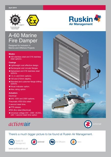
A-60 <strong>Marine</strong><br />
<strong>Fire</strong> <strong>Damper</strong><br />
Designed for inclusion in<br />
<strong>Marine</strong> and Offshore Projects<br />
Blades<br />
●430 stainless steel and 316 stainless<br />
steel options.<br />
Casings<br />
●Lightweight cost effective design.<br />
●Rectangular and circular flanges.<br />
●Galvanised and 316 stainless steel<br />
options.<br />
●1.2, 2, and 3mm options.<br />
●150 and 210mm depths.<br />
●Standard and customer flange drilling<br />
options.<br />
●Visual indicator option.<br />
●Atex rating option<br />
Actuators<br />
Electrical<br />
●24V, 120V and 230V options.<br />
Pneumatic ATEX (Ex) rated<br />
3 second reset time.<br />
●PTR release.<br />
ATEX (Ex) rated (Electrical)<br />
●Universal voltage 24V - 230V AC/DC,<br />
with 1 second reset time option<br />
actionair<br />
There’s a much bigger picture to be found at Ruskin Air Management.<br />
Ruskin Air<br />
Management<br />
actionair Air Diffusion naco<br />
www.actionair.co.uk
A-60 <strong>Marine</strong> <strong>Fire</strong> <strong>Damper</strong><br />
Introduction<br />
Specification<br />
<strong>Actionair</strong> has, for many years, been<br />
associated in the design,<br />
development and manufacture of life<br />
safety equipment, including the<br />
supply of fire damper products to the<br />
offshore and marine industry. The<br />
<strong>Actionair</strong> A-60 <strong>Marine</strong> <strong>Fire</strong> <strong>Damper</strong><br />
has been specifically engineered to<br />
meet stringent legislation.<br />
The A-60 <strong>Marine</strong> <strong>Fire</strong> <strong>Damper</strong><br />
compliments the comprehensive<br />
range of automatic fire and smoke<br />
dampers and associated controls,<br />
provides the complete solution for<br />
shipboard air conditioning and<br />
ventilation systems fire safety<br />
engineering strategies.<br />
The A-60 <strong>Marine</strong> <strong>Fire</strong> <strong>Damper</strong> has<br />
been designed for inclusion in air<br />
conditioning and ventilation systems,<br />
in dry filtered air, and is tested and<br />
approved for fitting to class A-60<br />
divisions (bulkheads and decks),<br />
when suitably insulated (refer to<br />
insulation details).<br />
The <strong>Actionair</strong> A-60 <strong>Marine</strong> <strong>Fire</strong><br />
<strong>Damper</strong> is constructed from<br />
galvanised steel 1.2mm thick, (2 and<br />
3mm options available), 40mm<br />
flanged rectangular or circular casing.<br />
All certificates are<br />
available via the<br />
<strong>Actionair</strong> website.<br />
www.actionair.co.uk<br />
Electrical<br />
The <strong>Actionair</strong> direct-coupled spring return<br />
fail-safe electrical control modes are fitted<br />
with halogen free low smoke and fume<br />
electrical cable. They have a 60 second reset<br />
time and a 20 second release time. Each<br />
actuator has a 72°C rated Electrical Thermal<br />
Release (ETR). The ETR incorporates a<br />
safety electrical interlock that only permits<br />
actuator operation when correctly fitted. A<br />
green 'Healthy' indication lamp is built into<br />
the ETR housing to give a simple and clear<br />
visual check that the actuator is receiving<br />
power, the ETR is correctly fitted, and the<br />
thermal fuse is intact. A manual test switch<br />
allowing periodic operation of the damper for<br />
testing purposes simulates actual fail-safe<br />
release under smoke/fire conditions. End<br />
switches are provided with each mode for<br />
reset and release monitoring.<br />
Electrical ATEX (Ex) rated<br />
The <strong>Actionair</strong> direct-coupled spring return<br />
fail-safe ATEX (Ex) electrical control modes<br />
are fitted with 1 metre of cable for<br />
connection inside hazardous areas.<br />
They have the benefit of a Universal<br />
electrical supply using any Voltage between<br />
24-230V AC/DC, which is self adaptable.<br />
They have Variable (3 -15-30-60-120 sec)<br />
Reset and (3 -10 sec ) Release times, which<br />
are selectable on site. Each actuator has a<br />
Integral Safety Temperature Sensor (ExPro-<br />
TT) rated at 72 °C. The ExPro-TT<br />
incorporates a triple fail-safe thermal fuse<br />
arrangement, 2 induct and one outside, to<br />
ensure the fail-safe actuator operates in all<br />
conditions. A manual test switch allowing<br />
periodic operation of the damper for testing<br />
purposes simulates actual fail-safe release<br />
under smoke/fire conditions. End switches<br />
are provided with each mode for reset and<br />
release monitoring. An Integral heater allows<br />
the unit to be operated within ambient<br />
temperatures down to – 40°C.<br />
Pneumatic ATEX (Ex) rated<br />
The <strong>Actionair</strong> direct coupled spring return<br />
fail-safe pneumatic control mode requires an<br />
air pressure of between 5 to 8 bar (72 to<br />
116 psi) to operate. They have 3 second<br />
reset and release time. Each actuator has a<br />
Pneumatic Thermal Release (PTR). The PTR<br />
assembly is supplied with 500mm nylon<br />
tubing that connects to the quick fit<br />
couplings of the PTR and actuator.<br />
Incorporated is a fail-safe 74 °C fusible link.<br />
When this operates, air exhausts from the<br />
actuator, permitting the spring return<br />
actuator to go to the fail-safe position, thus<br />
closing the damper. Switch box and<br />
solenoid accessories are available for<br />
monitoring and control.<br />
Testing - Maintenance and cleaning<br />
A-60 <strong>Damper</strong>s are supplied in 2 casing and<br />
blade options:-<br />
1. 430 Standard steel blades, Galvanised<br />
Steel casing - only suitable for installation in<br />
dry filtered systems.<br />
2. 316 Standard steel blades, casing and<br />
drive - more suited for corrosive conditions,<br />
but even this will rapidly corrode and fail if<br />
not properly maintained, when used in air<br />
intake systems at sea. The addition of a<br />
mist eliminator is highly recommended and<br />
access must be provided for maintenance.<br />
Pay particular attention to the blade rivets,<br />
where crevice corrosion will cause rapid<br />
failure of blades if not kept in check.<br />
Testing<br />
Two levels of testing exists.<br />
1. Routine testing<br />
Monthly, or in accordance with<br />
maintenance programme, release and reset<br />
damper (via control system or ETR test<br />
switch). Check remote indication or visual<br />
check of mechanical pointer as appropriate.<br />
2. Visual check at damper<br />
At commissioning and at least once a year,<br />
check damper operation by removing and<br />
re-applying power to actuator. (via ETR test<br />
switch). Visually check blades for damper<br />
closed and open positions. Prove remote<br />
indication if applicable.<br />
Routine Maintenance<br />
Depending upon environmental conditions,<br />
each damper will merit its own cleaning<br />
regime. Particularly hostile areas may<br />
require monthly cleaning and lubrication.<br />
‘Frequency of maintenance’ should be<br />
determined by collecting historical data<br />
from previous visits, and for this reason,<br />
commence maintenance programmes at<br />
very frequent intervals. <strong>Damper</strong>s in ‘Dry<br />
Filtered Air’ require very limited<br />
maintenance.<br />
Using Duck Oil (recommended lubricant, or<br />
similar equivalent), clean all exposed<br />
surfaces, using a cloth. Remove all traces<br />
of surface staining, as this will deteriorate<br />
further causing deeper material corrosion.<br />
If damper is stiff to operate, lubricate blade<br />
ends and open and close damper<br />
successively until the damper moves with<br />
ease. (This may necessitate removal of the<br />
actuator and operating the blades manually<br />
by the drive shaft). Refit actuator, and retest.<br />
Clean off excessive lubricant.<br />
2
A-60 <strong>Marine</strong> <strong>Fire</strong> <strong>Damper</strong><br />
Application<br />
The A-60 dampers can be used where the<br />
maximum system pressure is up to 1500<br />
Pa and duct velocities to 15m/s.<br />
Pay particular attention to the blade rivets,<br />
where crevice corrosion will cause rapid<br />
failure of blades if not kept in check.<br />
The A-60 <strong>Marine</strong> <strong>Fire</strong> <strong>Damper</strong> is suitable<br />
for both vertical and horizontal<br />
applications, with airflow in either direction.<br />
The dampers are normally open, and failsafe<br />
to the closed position.<br />
A-60 <strong>Damper</strong>s are supplied in 2 casing<br />
and blade options:-<br />
1. 430 Standard steel blades, Galvanised<br />
Steel casing - only suitable for installation<br />
in dry filtered systems.<br />
2. 316 Standard steel blades, casing and<br />
drive - more suited for corrosive<br />
conditions, but even this will rapidly<br />
corrode and fail if not properly maintained,<br />
when used in air intake systems at sea.<br />
The addition of a mist eliminator is highly<br />
recommended and access must be<br />
provided for maintenance.<br />
Casing Features<br />
The standard 1.2mm galvanised steel<br />
flanged type casing, (optional 2 and 3mm<br />
thick), having a single penetration for the<br />
drive control, complies to Class A & B of<br />
Eurovent 2/2 and Test Procedures for<br />
Classes A, B, & C of the HVCA Ductwork<br />
Specification DW144.<br />
Pre-punched bolt holes are provided as<br />
standard (refer to page 11).<br />
In addition stainless steel peripheral<br />
gasketing is included, which allows for<br />
expansion under full fire conditions.<br />
The 1.2mm casing has obvious benefits,<br />
for example being lighter in weight,<br />
allowing easier installation.<br />
Casings manufactured in 316 grade<br />
(Type 1.4401) Austenitic Stainless Steel<br />
are available as an optional extra.<br />
1.2mm Casing<br />
2 and 3mm Casing<br />
Casing Mounted ETR<br />
- 210mm deep casings only<br />
Factory fitted Actuator Options (Electrical only) - 210mm deep casings only<br />
A-60 Electrical with fitted ETR A-60 Electrical Atex with ExPro-TT<br />
Blade Features<br />
The damper blades are aerodynamic<br />
double skin at 75mm pitch which when<br />
closed, interlock to form a positive fire<br />
resisting shield: -<br />
430 grade (Type 1.4016) Ferritic stainless<br />
steel with sintered steel with steam oxide<br />
and oil dipped finish blade end bearings.<br />
316 grade (Type 1.4401) Austenitic<br />
stainless steel with sintered 316 austenitic<br />
stainless steel blade end bearings.<br />
12.7<br />
Optional Silicon blade seals can be<br />
provided for low leakage requirement<br />
at ambient temperature.<br />
41.5<br />
75<br />
actionair<br />
3
A-60 <strong>Marine</strong> <strong>Fire</strong> <strong>Damper</strong><br />
Insulation Details<br />
Bulkhead (Vertical)<br />
Deck (Horizontal)<br />
STRUCTURAL STEEL CORE<br />
50<br />
25<br />
40 40<br />
DAMPER<br />
See page 7<br />
300<br />
75<br />
See Below<br />
**<br />
COAMING<br />
MINERAL FIBRE<br />
INSULATION<br />
(110Kg PER<br />
CUBIC METRE)<br />
See ** Below<br />
COAMING<br />
225<br />
See ** Below<br />
See page 7<br />
CONNECTION OF DAMPER<br />
TO COAMING<br />
MINERAL FIBRE INSULATION<br />
(110Kg PER CUBIC METRE)<br />
CONNECTION<br />
OF DAMPER<br />
TO COAMING<br />
50<br />
40 25<br />
DAMPER<br />
40<br />
** Table of Minimum Total Coaming Insulation Length<br />
(Applies to all approval bodies)<br />
Application Insulation Thickness Minimum Total Insulation Length<br />
1. Vertical bulkhead up to 750 x 750 (0.5625msq)<br />
75mm<br />
725mm<br />
2. Vertical bulkhead above 0.5625 msq refer to graph below<br />
3. Horizontal deck up to 750 x 750 (0.5625msq)<br />
40mm<br />
725mm<br />
4. Horizontal deck above 0.5625 msq refer to graph below<br />
5. Horizontal deck (all sizes) 75mm 725mm<br />
The same area/insulation criteria applies for multiple arrangements<br />
Graph showing Minimum Insulation length for <strong>Damper</strong> above 750mm x 750mm Base <strong>Damper</strong><br />
(Applies to all approval bodies with the exception of ABS)<br />
Total Insulation length (mm)<br />
1100<br />
1050<br />
1000<br />
950<br />
900<br />
850<br />
800<br />
750<br />
700<br />
0.5 0.55 0.6 0.65 0.7 0.75<br />
0.8 0.85 0.9 0.95 1<br />
Area (msq)<br />
Coaming Insulation<br />
Example<br />
For a damper size of 910mm x 925mm.<br />
Area = 0.85 msq<br />
Vertical Installation<br />
Insulation Thickness = 75mm (line 2 of table)<br />
Insulation Length = 975mm (refer to graph)<br />
Horizontal Installation<br />
Insulation Thickness = 40mm (line 4 of table)<br />
Insulation Length = 975mm (refer to graph)<br />
Insulation Thickness = 75mm (line 5 of table)<br />
Insulation Length = 725mm (line 5 of table)<br />
Note: for circular, use square base damper area.<br />
4
A-60 <strong>Marine</strong> <strong>Fire</strong> <strong>Damper</strong><br />
Testing<br />
The <strong>Actionair</strong> A-60 <strong>Marine</strong> <strong>Fire</strong> <strong>Damper</strong><br />
has undergone extensive fire testing in<br />
single and multiple arrangements. The<br />
dampers were incorporated in steel<br />
bulkheads and decks and tested to the<br />
<strong>Marine</strong> <strong>Fire</strong> Resistance Test in<br />
accordance with IMO resolution A754.<br />
(18) for a duration of 60 minutes.<br />
Changes to the originally supplied<br />
product may invalidate the certification<br />
and/or warranty.<br />
Tests, approvals and certification<br />
<strong>Marine</strong> Equipment Directive (MED) 96/98/EC<br />
Lloyds Register Group Approval to IMO <strong>Fire</strong><br />
Test Procedures Code, Annex 1, Part 3, for<br />
Class <strong>A60</strong> bulkheads and decks.<br />
DNV (Det Norske Veritas) Type Approved.<br />
USCG Approved (product category 164.139).<br />
Germanischer Lloyds Approved to IMO Res.<br />
A.754 (18) and IMO Res. MSC61(67), Annex 1<br />
Part 3.<br />
American Bureau of Shipping Approved to<br />
2005 Steel Vessel Rules 1-1-4/7.7 (Please<br />
note maximum size restrictions – see page 4).<br />
Corrosion Tested to BSEN 60068-2-52,<br />
severity 2 conditions.<br />
Vibration Tested to BS EN 60068-2-6 (5Hz to<br />
350Hz @ 2g).<br />
Sira Certification (Ex) category 2 equipment.<br />
EC Type Examination (Module B) Certificate<br />
EC (Module D) Certificate of Conformity.<br />
Certificate of <strong>Fire</strong> Approval.<br />
ISO 9001:2008 Certification.<br />
Copies of all certification are available from our<br />
website.<br />
Changes/Modifications to the original supplied<br />
product may invalidate certification and/or<br />
warranty.<br />
actionair 5
A-60 <strong>Marine</strong> <strong>Fire</strong> <strong>Damper</strong><br />
Electrical Control Modes<br />
Standard Control Modes<br />
The IP54 rated Control Modes, are located<br />
outside of the ductwork for ease of access<br />
and installation. Control Modes fitted to<br />
dampers up to 400mm high, can be fitted<br />
in any one of three orientations i.e.<br />
vertically down,horizontally or vertically up.<br />
Positions 1, 2, or 3. Two sizes (Compact<br />
and Universal) of Control Mode are utilised.<br />
This flexibility ensures that the smaller<br />
damper sizes and Control Mode require<br />
the minimal amount of room. Correctly<br />
sized Control Modes are designed to fit<br />
only to the relevant sized damper.<br />
The control modes are direct coupled to<br />
the damper utilising a unique user friendly<br />
positive connection system. This allows the<br />
dampers and actuators to be supplied<br />
separately, offering shipping and storage<br />
benefits.<br />
Fig.1 Three Position Compact<br />
150<br />
or 210<br />
Position 3<br />
85<br />
Position 1<br />
100<br />
Position 2<br />
155<br />
30<br />
Control Mode Standard<br />
Parameters<br />
150<br />
or 210<br />
DAMPER HEIGHT<br />
400 1000<br />
Three Position<br />
Compact<br />
Fig. 1<br />
Three Position<br />
Universal<br />
Fig. 2<br />
Position 3<br />
123<br />
Position 2<br />
Position 1<br />
100<br />
100<br />
248<br />
100<br />
400 1000<br />
DAMPER WIDTH<br />
Fig.2 Three Position Universal<br />
CAP<br />
PROBE<br />
Electrical<br />
Fail-safe is by means of a unique and<br />
patented Electrical Thermal Release (ETR)<br />
which operates at 72 °C, or if power supply<br />
is interrupted. The ETR incorporates a<br />
safety feature, that ensures the fail-safe<br />
status of the damper if the ETR is not<br />
fitted on to the ductwork. Additionally a<br />
green LED lamp is built into the ETR<br />
housing. This gives the user a simple and<br />
clear visual check that the Actuator is<br />
receiving power, the ETR is correctly<br />
fitted, and the thermal fuse is intact.<br />
A manual test switch allows periodic<br />
operation of the damper for testing<br />
purposes, simulating actual fail-safe<br />
release under fire conditions.<br />
The associated electrical Control Modes<br />
are available in 24V, 120V or 230V<br />
versions.<br />
Also available with 95° Probe as an option.<br />
Probe section only available as a spare<br />
replacement part.<br />
6
A-60 <strong>Marine</strong> <strong>Fire</strong> <strong>Damper</strong><br />
Electrical Application and Wiring<br />
Standard Application and<br />
Wiring<br />
Mode 5 24V System<br />
Control Mode 5 24V AC or DC<br />
Control Mode 6 230V AC 50/60Hz<br />
Control Mode 120 120V AC 50/60Hz<br />
AC / DC 24V<br />
50 / 60 Hz<br />
M<br />
BLACK<br />
WHITE<br />
1<br />
2<br />
–<br />
+<br />
SUPPLY<br />
24V AC or DC<br />
TYPICALLY 10W<br />
(MOTORING)<br />
2W (RESET)<br />
24V - AC - 50/60Hz<br />
AC 19.2 - 28.8V<br />
DC 21.6 - 28.8V<br />
230V 196 - 264V<br />
120V 96 - 132V<br />
1<br />
2<br />
3<br />
VOLT FREE<br />
CONTACT MADE BETWEEN<br />
1 AND 2 WHEN DAMPER<br />
FULLY RELEASED<br />
Supply On - <strong>Damper</strong> motors open<br />
Supply Off - <strong>Damper</strong> springs closed<br />
ETR Operates - <strong>Damper</strong> springs closed<br />
12W (Maximum Motoring)<br />
4W (Maximum Reset)<br />
12.5 V A<br />
Max<br />
10 / 2 W<br />
Imax<br />
8.3A @ 5ms<br />
AC<br />
250V<br />
6(3)A<br />
4<br />
5<br />
6<br />
VOLT FREE<br />
CONTACT MADE BETWEEN<br />
4 AND 6 WHEN DAMPER<br />
FULLY RESET<br />
End Switches<br />
2 x SPDT 6(3)A, AC 250V<br />
To isolate from main power supply, the<br />
system must incorporate a device, which<br />
disconnects the phase conductors, with<br />
at least 3mm contact gap.<br />
–30...+50 C<br />
CONTINUOUS<br />
TF 72 C<br />
DIAGRAM SHOWS ACTUATOR IN FULLY RELEASED STATE<br />
ELECTRICAL THERMAL<br />
RELEASE (MUST BE FITTED<br />
FOR DAMPER OPERATION).<br />
(SPRING BIASED<br />
TEST SWITCH)<br />
2 x 1 metre of halogen free, low smoke<br />
and fume electric cables are included with<br />
each control mode. The ETR is also prewired<br />
with 0.5 metre halogen free low<br />
smoke and fume cable.<br />
Mode 6 230V System (Also 120V Typical)<br />
AC 230V<br />
50 / 60 Hz<br />
M<br />
BLUE<br />
BROWN<br />
N<br />
L1<br />
SUPPLY<br />
230VAC 50/60 Hz<br />
TYPICALLY12W (MOTORING)<br />
4W (RESET<br />
1<br />
2<br />
3<br />
VOLT FREE<br />
CONTACT MADE BETWEEN<br />
1 AND 2 WHEN DAMPER<br />
FULLY RELEASED<br />
14 V A<br />
Max<br />
12 / 4 W<br />
AC<br />
250V<br />
6(3)A<br />
4<br />
5<br />
6<br />
VOLT FREE<br />
CONTACT MADE BETWEEN<br />
4 AND 6 WHEN DAMPER<br />
FULLY RESET<br />
– 30...+50 C<br />
CONTINUOUS<br />
TF 72 C<br />
ELECTRICAL THERMAL<br />
RELEASE (MUST BE FITTED<br />
FOR DAMPER OPERATION).<br />
(SPRING BIASED<br />
TEST SWITCH)<br />
DIAGRAM SHOWS ACTUATOR IN FULLY RELEASED STATE<br />
actionair 7
A-60 <strong>Marine</strong> <strong>Fire</strong> <strong>Damper</strong><br />
ATEX (Ex) Rated Control Modes<br />
The ATEX rated Control Modes, are<br />
located outside of the ductwork for ease<br />
of access and installation.<br />
Control Modes can be fitted in any one of<br />
three orientations, i.e. vertically down,<br />
horizontally or vertically up. Positions 1, 2,<br />
or 3.<br />
The control modes are direct coupled to<br />
the damper utilising a unique user friendly<br />
positive connection system. This allows<br />
the dampers and actuators to be supplied<br />
separately, offering shipping and storage<br />
benefits.<br />
Position 3<br />
231<br />
44<br />
97<br />
Position 2<br />
Position 1<br />
Electrical ATEX (Ex) rated.<br />
Fail-safe is by means of a ExPro-TT<br />
which operates at 72 °C, or if power<br />
supply is interrupted.<br />
A manual test switch allows periodic<br />
operation of the damper for testing<br />
purposes, simulating actual fail-safe<br />
release under fire conditions.<br />
The associated electrical Control Modes<br />
are available in one Universal version with<br />
24 – 230V AC/DC supply.<br />
ExPro-TT<br />
8
A-60 <strong>Marine</strong> <strong>Fire</strong> <strong>Damper</strong><br />
ATEX (Ex) Rated Actuator, Application and Wiring<br />
Atex (Ex) Rated Electrical Control Modes<br />
On-off 1-wire-spring return + Ex-i circuit<br />
Universal supply unit from 24 to 230V-AC/DC, 50/60 Hz.<br />
Supply On - <strong>Damper</strong> motors open.<br />
Supply Off - <strong>Damper</strong> springs closed.<br />
ExPro-TT Operates - <strong>Damper</strong> springs closed.<br />
20W (Maximum Blocking),<br />
16W (Heater).<br />
End Switches Rated at 250V 1.5 Amp (Maximum).<br />
To isolate from main power supply, the system must incorporate<br />
a device, which disconnects the phase conductors, with at least<br />
3mm contact gap.<br />
24...240 VAC/DC<br />
PE<br />
–<br />
~<br />
+<br />
~<br />
Attention<br />
If you use this<br />
type of wiring the<br />
heater does not<br />
work in case of<br />
open contact<br />
Integrated aux, switches<br />
max 24V/3A, 240V/0.25A<br />
min. 5V/10mA, switching<br />
at 5° and 85°.<br />
Supply at aux. switches<br />
must be the same like<br />
supply of the actuator<br />
< 5° < 85°<br />
Ex-i circuit for<br />
passive + potential<br />
free push button on<br />
site and safety<br />
temperature sensor<br />
(Type ExPro -TT<br />
accessories)<br />
ExPro -TT<br />
°C<br />
Push button<br />
A metre of halogen free, low smoke and fume electric cable is<br />
included with each control mode. The ExPro-TT is also prewired<br />
with a metre of halogen free low smoke and fume cable.<br />
1<br />
2<br />
Heater<br />
3 4 5 6 7 8 9 10 11 1 2<br />
Standard wiring = spring return in ~10 sec.<br />
Additional wiring terminal 5 = spring return in ~3 sec.<br />
PA<br />
Power input depending on supply voltage<br />
Power supply design<br />
The design of the on-site supply, depends on the selected motor<br />
running time and selected supply voltage. Accompanying values<br />
are “about values”, since there can be construction unit<br />
dispersions within electronics. The power consumption in the<br />
blocking position is run time independently with max 20W. The<br />
power consumption for the heater is approximately 16W. The<br />
heating is running only if the motor is in idle position. The initial<br />
starting supply voltage required by the actuators power supply<br />
unit is around 2.0A for about 1 sec. (Please consider this while<br />
calculating the cross section area of the supply line.)<br />
Rated current in acc. with motor running time<br />
Voltage Current 3/7,5s 15s 30s 60s 120s<br />
230V Irated 0.5A 0.3A 0.15A 0.10A 0.10A<br />
120V Irated 0.75A 0.4A 0.3A 0.25A 0.25A<br />
48V Irated 2.0A 0.5A 0.3A 0.2A 0.2A<br />
24V Irated 4.7A 1.45A 0.52A 0.4A 0.4A<br />
Dimensioning of the line cross section with 24 to<br />
48 Volt AC/DC supply voltages<br />
Dimensioning / Design of the supply line<br />
On long distances between supply and actuator, voltage drop<br />
occurs due to line resistances. On 24V AC/DC systems the<br />
actuator receives a low voltage and does not start. In order to<br />
prevent this, the cross section of the inlet line is to be<br />
designed/dimensioned accordingly. The accompanying formula<br />
allows the calculation of the required line cross section area and<br />
indicates the maximum length utilising an existing line.<br />
Alternatively the secondary voltage can be increased by selecting<br />
a transformer to overcome the loss.<br />
For calculation purposes, following characteristics are essential:<br />
UV = supply voltage in [V]<br />
A = line cross section in [mm 2 ]<br />
L = line length in [m]<br />
Factor 0.0714 = drive-specific factor<br />
[Vmm 2 /m] 9 based on the electrical conductivity of copper with a<br />
coefficient of 56/Wmm 2 )<br />
Uv [m]<br />
28<br />
27<br />
26<br />
25<br />
24<br />
23<br />
22<br />
21<br />
20<br />
.75 1mm2 1.5mm 2 2.0 2.5mm 2 4mm 2<br />
50 100 150 200 250 300 350 400 L [m]<br />
Example:<br />
24V power supply with diameter 1.5mm 2 = 126m<br />
Panel<br />
Voltage<br />
“Uv” [V]<br />
Formula for maximum cable<br />
length “L” at cable cross<br />
section “A”<br />
L = A(Uv-18V) 0.0714<br />
Example:<br />
A = 1.5mm 2 , Uv = 24V<br />
Length of cable L = 126m<br />
Line cross section “A” [mm 2 ]<br />
Lenght “L” [m]<br />
Terminal box<br />
Actuator<br />
Formula of needed cable<br />
cross section “A” at a cable<br />
length of “L”<br />
A = 0.0714 L(Uv-18V)<br />
Example:<br />
L = 250m, Uv = 30V<br />
Cross section of A = 1.5mm 2<br />
actionair 9
A-60 <strong>Marine</strong> <strong>Fire</strong> <strong>Damper</strong><br />
Festo Actuators and Accessories<br />
All dimension are in millimetres<br />
Pneumatic<br />
The special purpose design Pneumatic<br />
Thermal Release (PTR) assembly is supplied<br />
with 500mm nylon tubing that connects to<br />
the quick fit couplings of the PTR and<br />
actuator. Incorporated is a failsafe 74°C<br />
fusible link. When this activates, air exhausts<br />
from the actuator, enabling the PTR to spring<br />
return to the fail-safe position, thus closing<br />
the damper.<br />
Pneumatic Operation<br />
Air On - <strong>Damper</strong> opens.<br />
Air Off - Spring closure.<br />
Release time ≈ 2 - 4 secs.<br />
Reset time ≈ 2 - 4 secs.<br />
Air inlet 6mm dia. quick fit coupling.<br />
74 °C Pneumatic Thermal Release (PTR).<br />
Air pressure = 5.5 - 8.0 Bar.<br />
External mechanical position indicator.<br />
Test operation by removing fusible link<br />
element.<br />
Pneumatic Thermal Release (PTR)<br />
4mm diameter tubing 500mm<br />
length connection to actuator<br />
2 off quick<br />
release<br />
connectors,<br />
supplied<br />
Input:<br />
6mm diameter,<br />
quick release<br />
connector,<br />
pressure range<br />
5 - 8 Bar<br />
Dimensional Data<br />
Festo Actuator with Solenoid and Status Beacon<br />
236<br />
25<br />
84<br />
104<br />
204<br />
MINIMAL REMOVAL<br />
DISTANCE 224mm<br />
153<br />
40<br />
Hytork actuators and<br />
accessories are<br />
available as an option.<br />
10
A-60 <strong>Marine</strong> <strong>Fire</strong> <strong>Damper</strong><br />
Dimensional Data<br />
All dimension are in millimetres<br />
Square and Rectangular (A-60 RECT)<br />
*Width, height and diameters available in 1mm increments<br />
51<br />
150<br />
or<br />
210<br />
MIN<br />
75<br />
MAX<br />
150<br />
150<br />
TYPICAL<br />
MIN<br />
75<br />
MAX<br />
150<br />
Ø12mm<br />
Holes<br />
40<br />
Circular (A-60 CIRC)<br />
230<br />
or<br />
290<br />
40<br />
SEE TABLE BELOW<br />
FOR NUMBER OF<br />
HOLES, TO BE<br />
EQUALLY SPACED<br />
ON PCD<br />
ALIGNMENT OF<br />
HOLES TAKEN<br />
FROM CENTRE<br />
LINE OF SQUARE<br />
SECTION PLATE<br />
FLANGE ALL<br />
ROUND<br />
40<br />
MIN<br />
75<br />
MAX<br />
150<br />
TYPICAL<br />
MIN<br />
75<br />
MAX<br />
150<br />
FRONT<br />
DAMPER HEIGH T*<br />
100 -1000<br />
DAMPER DIA * 100 -1000<br />
FRONT<br />
DAMPER WIDTH *<br />
100 - 1000<br />
20<br />
TYPICAL<br />
20<br />
TYPICAL<br />
40<br />
PCD = NOM .<br />
DIA. + 40mm<br />
HOLE DIM.<br />
SEE TABLE<br />
BELOW<br />
Electrical Actuator Atex Electrical Festo<br />
Option for Circular Flange on front<br />
or rear only<br />
61<br />
90<br />
85<br />
Circular <strong>Damper</strong> Fixing Hole Details<br />
<strong>Damper</strong> Dia.No. of Holes Hole Dia.<br />
78<br />
98<br />
MINIMUM<br />
MINIMUM<br />
REMOVAL<br />
REMOVAL<br />
40 40 40<br />
DIMENSION<br />
DIMENSION<br />
90mm<br />
110mm<br />
97<br />
79<br />
MINIMUM<br />
REMOVAL<br />
DIMENSION<br />
104mm<br />
100 - 250 4 off 7.0<br />
251 - 500 8 off 10.0<br />
501 - 750 12 off 12.0<br />
751 - 1000 16 off 12.0<br />
Multiple Assemblies<br />
150<br />
or<br />
210<br />
75mm WIDE<br />
JOINING STRIP. (BOTH SIDES)<br />
RIVETTED WITH 3.2mm STEEL<br />
RIVETS AT 100mm CENTRES,<br />
ON SITE BY OTHERS<br />
51 TOP<br />
DAMPER WIDTH 1580 Maximum<br />
Multiple width assemblies (2 x 1) have<br />
been tested and approved to a size of<br />
1580mm wide x 750mm high.<br />
ACTUATOR<br />
ACTUATOR<br />
DAMPER HEIGHT<br />
750 Maximum<br />
FRONT<br />
FRONT<br />
20<br />
TYPICAL<br />
20<br />
TYPICAL<br />
12mm Holes<br />
actionair 11
A-60 <strong>Marine</strong> <strong>Fire</strong> <strong>Damper</strong><br />
Weights<br />
1.2mm Galvanised Casings, 150mm Deep<br />
Weights (kg) of A-60 Rectangular (Excluding Actuator)<br />
100 200 300 400 500 600 700 800 900 1000<br />
100 3.0 3.8 4.6 5.5 6.3 7.1 8.0 8.8 9.7 10.5<br />
200 4.1 5.0 5.9 6.9 7.8 8.7 9.6 10.5 11.4 12.3<br />
300 5.3 6.4 7.4 8.4 9.5 10.5 11.5 12.6 13.6 14.7<br />
400 6.2 7.3 8.4 9.5 10.6 11.7 12.8 13.9 15.0 16.1<br />
500 7.4 8.6 9.7 10.9 12.1 13.3 14.4 15.6 16.8 18.0<br />
600 8.6 9.9 11.2 12.5 13.8 15.1 16.4 17.7 19.0 20.4<br />
700 9.5 10.9 12.2 13.6 15.0 16.3 17.7 19.1 20.5 21.8<br />
800 10.3 11.8 13.2 14.7 16.1 17.5 19.0 20.4 21.9 23.3<br />
900 11.5 13.1 14.7 16.3 17.8 19.4 21.0 22.6 24.1 25.7<br />
1000 12.4 14.1 15.7 17.4 19.0 20.6 22.3 23.9 25.6 27.2<br />
Weights<br />
(kg) of A-60 Circular<br />
(Excluding Actuator)<br />
100 Dia. 4.6<br />
200 Dia. 8.1<br />
300 Dia. 12.0<br />
400 Dia. 15.4<br />
500 Dia. 19.8<br />
600 Dia. 24.6<br />
700 Dia. 28.9<br />
800 Dia. 33.6<br />
900 Dia. 39.4<br />
1000 Dia. 44.5<br />
Compact Including Adaptor Plate 1.85kg<br />
Universal Including Adaptor Plate 3.00kg<br />
Pneumatic Including Adaptor Plate 3.00kg<br />
Electrical Atex Including Adaptor Plate 3.50kg<br />
2mm Galvanised Casings, 150mm Deep<br />
Weights (kg) of A-60 Rectangular (Excluding Actuator)<br />
100 200 300 400 500 600 700 800 900 1000<br />
100 4.1 5.3 6.4 7.6 8.8 10.0 11.1 12.3 13.5 14.7<br />
200 5.6 6.8 8.1 9.3 10.5 11.8 13.0 14.3 15.5 16.7<br />
300 7.1 8.4 9.8 11.2 12.6 13.9 15.3 16.7 18.0 19.4<br />
400 8.2 9.7 11.1 12.5 14.0 15.4 16.9 18.3 19.7 21.2<br />
500 9.8 11.3 12.8 14.3 15.8 17.3 18.8 20.3 21.8 23.3<br />
600 11.3 12.9 14.5 16.2 17.8 19.5 21.1 22.8 24.4 26.0<br />
700 12.4 14.2 15.9 17.6 19.3 21.0 22.7 24.4 26.1 27.8<br />
800 13.6 15.4 17.2 18.9 20.7 22.5 24.3 26.1 27.8 29.6<br />
900 15.1 17.0 18.9 20.9 22.8 24.7 26.6 28.5 30.4 32.3<br />
1000 16.3 18.3 20.3 22.2 24.2 26.2 28.2 30.2 32.1 34.1<br />
Weights<br />
(kg) of A-60 Circular<br />
(Excluding Actuator)<br />
100 Dia. 6.1<br />
200 Dia. 10.7<br />
300 Dia. 15.6<br />
400 Dia. 20.1<br />
500 Dia. 25.6<br />
600 Dia. 31.6<br />
700 Dia. 37.0<br />
800 Dia. 43.0<br />
900 Dia. 50.1<br />
1000 Dia. 56.4<br />
Compact Including Adaptor Plate 1.85kg<br />
Universal Including Adaptor Plate 3.00kg<br />
Pneumatic Including Adaptor Plate 3.00kg<br />
Electrical Atex Including Adaptor Plate 3.50kg<br />
3mm Galvanised Casings, 150mm Deep<br />
Weights (kg) of A-60 Rectangular (Excluding Actuator)<br />
100 200 300 400 500 600 700 800 900 1000<br />
100 5.5 7.1 8.7 10.3 11.9 13.5 15.1 16.7 18.3 19.9<br />
200 7.4 9.1 10.7 12.4 14.0 15.7 17.4 19.0 20.7 22.4<br />
300 9.3 11.1 12.9 14.7 16.5 18.2 20.1 21.8 23.6 25.4<br />
400 10.8 12.7 14.5 16.4 18.3 20.1 22.0 23.9 25.7 27.6<br />
500 12.7 14.7 16.6 18.5 20.5 22.4 24.3 26.3 28.2 30.1<br />
600 14.6 16.7 18.7 20.8 22.9 24.9 27.0 29.1 31.1 33.2<br />
700 16.2 18.3 20.4 22.6 24.7 26.8 29.0 31.1 33.3 35.4<br />
800 17.7 19.9 22.1 24.3 26.5 28.7 31.0 33.1 35.3 37.6<br />
900 19.6 22.0 24.3 26.6 29.0 31.3 33.6 36.0 38.3 40.7<br />
1000 21.2 23.6 26.0 28.4 30.8 33.2 35.6 38.0 40.4 42.8<br />
Weights<br />
(kg) of A-60 Circular<br />
(Excluding Actuator)<br />
100 Dia. 8.4<br />
200 Dia. 14.5<br />
300 Dia. 21.1<br />
400 Dia. 27.3<br />
500 Dia. 34.5<br />
600 Dia. 42.4<br />
700 Dia. 49.7<br />
800 Dia. 57.6<br />
900 Dia. 66.7<br />
1000 Dia. 75.1<br />
Compact Including Adaptor Plate 1.85kg<br />
Universal Including Adaptor Plate 3.00kg<br />
Pneumatic Including Adaptor Plate 3.00kg<br />
Electrical Atex Including Adaptor Plate 3.50kg<br />
1.2mm 316 Stainless Steel Casings, 150mm Deep<br />
Weights (kg) of A-60 Rectangular (Excluding Actuator)<br />
100 200 300 400 500 600 700 800 900 1000<br />
100 3.0 3.9 4.7 5.6 6.4 7.3 8.1 9.0 9.8 10.7<br />
200 4.2 5.1 6.0 7.0 7.9 8.8 9.7 10.6 11.6 12.5<br />
300 5.4 6.4 7.5 8.6 9.6 10.7 11.8 12.8 13.9 15.0<br />
400 6.2 7.4 8.5 9.7 10.8 11.9 13.1 14.2 15.3 16.5<br />
500 7.5 8.7 9.9 11.1 12.3 13.5 14.7 15.9 17.1 18.4<br />
600 8.7 10.1 11.4 12.8 14.1 15.5 16.8 18.2 19.5 20.9<br />
700 9.6 11.0 12.4 13.9 15.3 16.7 18.1 19.5 21.0 22.4<br />
800 10.5 12.0 13.5 15.0 16.4 17.9 19.4 20.9 22.4 23.9<br />
900 11.7 13.3 15.0 16.6 18.2 19.9 21.5 23.1 24.8 26.4<br />
1000 12.6 14.3 16.0 17.7 19.4 21.1 22.8 24.5 26.2 27.9<br />
Weights<br />
(kg) of A-60 Circular<br />
(Excluding Actuator)<br />
100 Dia. 4.7<br />
200 Dia. 8.2<br />
300 Dia. 12.2<br />
400 Dia. 15.7<br />
500 Dia. 20.1<br />
600 Dia. 25.1<br />
700 Dia. 29.5<br />
800 Dia. 34.3<br />
900 Dia. 40.4<br />
1000 Dia. 45.5<br />
Compact Including Adaptor Plate 1.85kg<br />
Universal Including Adaptor Plate 3.00kg<br />
Pneumatic Including Adaptor Plate 3.00kg<br />
Electrical Atex Including Adaptor Plate 3.50kg<br />
12
A-60 <strong>Marine</strong> <strong>Fire</strong> <strong>Damper</strong><br />
Weights<br />
2mm 316 Stainless Steel Casings, 150mm Deep<br />
Weights (kg) of A-60 Rectangular (Excluding Actuator)<br />
100 200 300 400 500 600 700 800 900 1000<br />
100 4.2 5.3 6.5 7.7 8.9 10.1 11.3 12.5 13.7 14.9<br />
200 5.6 6.9 8.2 9.4 10.7 12.0 13.2 14.5 15.7 17.0<br />
300 7.2 8.6 10.0 11.4 12.8 14.2 15.6 17.0 18.4 19.8<br />
400 8.3 9.8 11.3 12.8 14.2 15.7 17.2 18.7 20.1 21.6<br />
500 9.9 11.4 13.0 14.5 16.1 17.6 19.2 20.7 22.3 23.8<br />
600 11.4 13.1 14.8 16.5 18.2 19.8 21.5 23.2 24.9 26.6<br />
700 12.6 14.4 16.1 17.9 19.6 21.4 23.2 24.9 26.7 28.5<br />
800 13.8 15.6 17.4 19.3 21.1 22.9 24.8 26.6 28.4 30.3<br />
900 15.3 17.3 19.3 21.2 23.2 25.2 27.2 29.1 31.1 33.1<br />
1000 16.5 18.5 20.6 22.6 24.7 26.7 28.8 30.8 32.9 34.9<br />
Weights<br />
(kg) of A-60 Circular<br />
(Excluding Actuator)<br />
100 Dia. 6.2<br />
200 Dia. 10.8<br />
300 Dia. 15.9<br />
400 Dia. 20.5<br />
500 Dia. 26.0<br />
600 Dia. 32.2<br />
700 Dia. 37.8<br />
800 Dia. 43.8<br />
900 Dia. 51.1<br />
1000 Dia. 57.6<br />
Compact Including Adaptor Plate 1.85kg<br />
Universal Including Adaptor Plate 3.00kg<br />
Pneumatic Including Adaptor Plate 3.00kg<br />
Electrical Atex Including Adaptor Plate 3.50kg<br />
3mm 316 Stainless Steel Casings, 150mm Deep<br />
Weights (kg) of A-60 Rectangular (Excluding Actuator)<br />
100 200 300 400 500 600 700 800 900 1000<br />
100 5.6 7.2 8.8 10.4 12.0 13.7 15.3 16.9 18.5 20.1<br />
200 7.5 9.1 10.8 12.5 14.2 15.9 17.6 19.3 20.9 22.6<br />
300 9.3 11.2 13.0 14.8 16.7 18.5 20.3 22.2 24.0 25.8<br />
400 10.9 12.8 14.7 16.6 18.5 20.4 22.3 24.2 26.1 28.0<br />
500 12.8 14.8 16.8 18.8 20.7 22.7 24.7 26.6 28.6 30.6<br />
600 14.7 16.9 19.0 21.1 23.2 25.3 27.4 29.5 31.7 33.8<br />
700 16.3 18.5 20.7 22.9 25.1 27.3 29.4 31.6 33.8 36.0<br />
800 17.9 20.2 22.4 24.7 26.9 29.2 31.4 33.7 36.0 38.2<br />
900 19.8 22.2 24.6 27.0 29.4 31.8 34.2 36.6 39.0 41.4<br />
1000 21.4 23.9 26.3 28.80 31.3 33.7 36.2 38.7 41.2 43.6<br />
Weights<br />
(kg) of A-60 Circular<br />
(Excluding Actuator)<br />
100 Dia. 8.5<br />
200 Dia. 14.7<br />
300 Dia. 21.4<br />
400 Dia. 27.7<br />
500 Dia. 35.0<br />
600 Dia. 43.1<br />
700 Dia. 50.5<br />
800 Dia. 58.6<br />
900 Dia. 67.9<br />
1000 Dia. 76.5<br />
Compact Including Adaptor Plate 1.85kg<br />
Universal Including Adaptor Plate 3.00kg<br />
Pneumatic Including Adaptor Plate 3.00kg<br />
Electrical Atex Including Adaptor Plate 3.50kg<br />
2mm Galvanised Casings, 210mm Deep<br />
Weights (kg) of A-60 Rectangular (Excluding Actuator)<br />
100 200 300 400 500 600 700 800 900 1000<br />
100 4.8 6.1 7.5 8.9 10.2 11.6 12.9 14.3 15.7 17.0<br />
200 6.4 7.9 9.3 10.7 12.1 13.6 15.0 16.4 17.9 19.3<br />
300 8.1 9.7 11.2 12.8 14.4 15.9 17.5 19.0 20.6 22.2<br />
400 9.5 11.1 12.7 14.3 16.0 17.6 19.2 20.9 22.5 24.1<br />
500 11.2 12.9 14.6 16.3 18.0 19.7 21.4 23.1 24.7 26.5<br />
600 12.9 14.7 16.5 18.4 20.2 22.0 23.9 25.7 27.5 29.4<br />
700 14.2 16.1 18.0 19.9 21.8 23.7 25.6 27.5 29.4 31.3<br />
800 15.6 17.6 19.5 21.5 23.5 25.4 27.4 29.4 31.3 33.3<br />
900 17.3 19.4 21.5 23.6 25.7 27.8 29.9 32.0 34.1 36.2<br />
1000 18.7 20.8 23.0 25.2 27.3 29.5 31.7 33.8 36.0 38.2<br />
Weights<br />
(kg) of A-60 Circular<br />
(Excluding Actuator)<br />
100 Dia. 6.8<br />
200 Dia. 11.7<br />
300 Dia. 17.0<br />
400 Dia. 21.9<br />
500 Dia. 27.8<br />
600 Dia. 34.2<br />
700 Dia. 40.0<br />
800 Dia. 46.3<br />
900 Dia. 53.8<br />
1000 Dia. 60.4<br />
Compact Including Adaptor Plate 1.85kg<br />
Universal Including Adaptor Plate 3.00kg<br />
Pneumatic Including Adaptor Plate 3.00kg<br />
Electrical Atex Including Adaptor Plate 3.50kg<br />
3mm Galvanised Casings, 210mm Deep<br />
Weights (kg) of A-60 Rectangular (Excluding Actuator)<br />
100 200 300 400 500 600 700 800 900 1000<br />
100 6.5 8.4 10.3 12.2 14.0 15.9 17.8 19.7 21.6 23.4<br />
200 8.7 10.6 12.6 14.5 16.5 18.4 20.4 22.3 24.2 26.2<br />
300 10.8 12.9 15.0 17.1 19.2 21.2 23.3 25.4 27.5 29.6<br />
400 12.7 14.8 16.9 19.1 21.2 23.4 25.5 27.7 29.8 32.0<br />
500 14.9 17.1 19.3 21.5 23.7 25.9 28.2 30.4 32.6 34.8<br />
600 17.0 19.4 21.7 24.1 26.4 28.8 31.1 33.5 35.8 38.2<br />
700 18.9 21.3 23.7 26.1 28.5 31.0 33.4 35.8 38.2 40.6<br />
800 20.7 23.2 25.7 28.2 30.7 33.1 35.6 38.1 40.6 43.1<br />
900 22.9 25.5 28.1 30.8 33.4 36.0 38.6 41.2 43.8 46.5<br />
1000 24.7 27.4 30.1 32.8 35.5 38.2 40.9 43.5 46.2 48.9<br />
Weights<br />
(kg) of A-60 Circular<br />
(Excluding Actuator)<br />
100 Dia. 9.4<br />
200 Dia. 16.1<br />
300 Dia. 23.2<br />
400 Dia. 30.0<br />
500 Dia. 37.8<br />
600 Dia. 46.2<br />
700 Dia. 54.1<br />
800 Dia. 62.5<br />
900 Dia. 72.2<br />
1000 Dia. 81.2<br />
Compact Including Adaptor Plate 1.85kg<br />
Universal Including Adaptor Plate 3.00kg<br />
Pneumatic Including Adaptor Plate 3.00kg<br />
Electrical Atex Including Adaptor Plate 3.50kg<br />
actionair 13
A-60 <strong>Marine</strong> <strong>Fire</strong> <strong>Damper</strong><br />
Weights<br />
2mm 316 Stainless Steel Casings, 210mm Deep<br />
Weights (kg) of A-60 Rectangular (Excluding Actuator)<br />
100 200 300 400 500 600 700 800 900 1000<br />
100 4.8 6.2 7.6 9.0 10.4 11.7 13.1 14.5 15.9 17.3<br />
200 6.5 8.0 9.4 10.9 12.3 13.8 15.2 16.7 18.2 19.6<br />
300 8.2 9.8 11.4 13.0 14.6 16.2 17.8 19.4 21.0 22.6<br />
400 9.6 11.2 12.9 14.6 16.2 17.9 19.6 21.3 22.9 24.6<br />
500 11.3 13.1 14.8 16.5 18.3 20.0 21.8 23.5 25.2 27.0<br />
600 13.0 14.9 16.8 18.7 20.6 22.4 24.3 26.2 28.1 30.0<br />
700 14.4 16.4 18.3 20.3 22.2 24.2 26.2 28.1 30.1 32.0<br />
800 15.8 17.8 19.8 21.9 23.9 25.9 28.0 30.0 32.0 34.0<br />
900 17.5 19.7 21.8 24.0 26.2 28.4 30.5 32.7 34.9 37.0<br />
1000 18.9 21.1 23.4 25.6 27.9 30.1 32.3 34.6 36.8 39.1<br />
Weights<br />
(kg) of A-60 Circular<br />
(Excluding Actuator)<br />
100 Dia. 6.9<br />
200 Dia. 11.9<br />
300 Dia. 17.3<br />
400 Dia. 22.3<br />
500 Dia. 28.3<br />
600 Dia. 34.8<br />
700 Dia. 40.7<br />
800 Dia. 47.2<br />
900 Dia. 55.9<br />
1000 Dia. 61.7<br />
Compact Including Adaptor Plate 1.85kg<br />
Universal Including Adaptor Plate 3.00kg<br />
Pneumatic Including Adaptor Plate 3.00kg<br />
Electrical Atex Including Adaptor Plate 3.50kg<br />
3mm 316 Stainless Steel Casings, 210mm Deep<br />
Weights (kg) of A-60 Rectangular (Excluding Actuator)<br />
100 200 300 400 500 600 700 800 900 1000<br />
100 6.6 8.5 10.4 12.3 14.2 16.1 18.0 19.9 21.8 23.7<br />
200 8.8 10.7 12.7 14.7 16.7 18.6 20.6 22.6 24.6 26.5<br />
300 10.9 13.1 15.2 17.3 19.4 21.5 23.6 25.8 27.9 30.0<br />
400 12.8 15.0 17.2 19.3 21.5 23.7 25.9 28.1 30.3 32.5<br />
500 15.0 17.3 19.5 21.8 24.0 26.3 28.6 30.8 33.1 35.3<br />
600 17.2 19.6 22.0 24.4 26.8 29.2 31.6 34.0 36.4 38.8<br />
700 19.1 21.5 24.0 26.5 29.0 31.4 33.9 36.4 38.9 41.3<br />
800 20.9 23.5 26.0 28.6 31.1 33.7 36.2 38.7 41.3 43.8<br />
900 23.1 25.8 28.5 31.2 33.9 36.6 39.3 41.9 44.6 47.3<br />
1000 25.0 27.7 30.5 33.3 36.0 38.8 41.6 44.3 47.1 49.8<br />
Weights<br />
(kg) of A-60 Circular<br />
(Excluding Actuator)<br />
100 Dia. 9.6<br />
200 Dia. 16.3<br />
300 Dia. 23.5<br />
400 Dia. 30.4<br />
500 Dia. 38.4<br />
600 Dia. 47.0<br />
700 Dia. 55.0<br />
800 Dia. 63.6<br />
900 Dia. 73.5<br />
1000 Dia. 82.7<br />
Compact Including Adaptor Plate 1.85kg<br />
Universal Including Adaptor Plate 3.00kg<br />
Pneumatic Including Adaptor Plate 3.00kg<br />
Electrical Atex Including Adaptor Plate 3.50kg<br />
<strong>Damper</strong> Release and Indication Module (DRIM)<br />
This is designed for control and monitoring<br />
of the electrically operated A-60 <strong>Marine</strong><br />
<strong>Fire</strong> <strong>Damper</strong>s.<br />
It will operate from 24V, 120V or 230V<br />
supplies, 50 or 60 Hz.<br />
Selection of the operating voltage is by<br />
use of internal links on the PCB, prior to<br />
installation and connection of actuator<br />
and supply.<br />
The DRIM may be used singly to provide<br />
local damper control, or in pairs to<br />
provide control from either side of a<br />
damper. It can also operate 2 actuators<br />
when dampers are provided in 2 multiple<br />
sections<br />
LED position and operation indication is<br />
provided.<br />
Operation is by push button to close and<br />
twist to re-open damper.<br />
Tested to BS EN 61010 -1: 2001 and is<br />
CE compliant.<br />
IP44 rated.<br />
Operating range 5 - 40 °C.<br />
Visual Indication<br />
Visual indication non<br />
drive side<br />
Option to have drive blade visual<br />
indication, non drive side only.<br />
Red indicates damper closed<br />
Green indicates damper open.<br />
14
A-60 <strong>Marine</strong> <strong>Fire</strong> <strong>Damper</strong><br />
Acoustic Data<br />
The data presented is from the<br />
Laboratory Determination of Acoustic and<br />
Aerodynamic Performance of A-60 <strong>Marine</strong><br />
<strong>Fire</strong> <strong>Damper</strong>s.<br />
A programme of extensive tests was<br />
carried out by an independent test facility,<br />
approved under the NAMAS Scheme, in<br />
accordance with BRITISH STANDARDS<br />
Nos. 4196, 4773, 4856, 4857 and 4954.<br />
From the selection of a duct velocity<br />
within the operational parameters of the<br />
damper a resultant pressure drop from<br />
Table 1 can be determined and the sum<br />
of these two components applied to the<br />
Velocity x Pressure Drop Vs Sound Power<br />
Level Graph. (Table 2).<br />
The graph is the result of a full<br />
range of acoustic tests with the blades<br />
set in the fully open position.<br />
Example:<br />
Duct with a design velocity of 8 m/sec<br />
and the A-60 <strong>Marine</strong> <strong>Fire</strong> <strong>Damper</strong> RECT<br />
damper blades in the fully open position.<br />
Pressure Drop = 22 Pa (Table 1).<br />
Multiply Velocity x Pressure Drop<br />
8 x 22 = 176.<br />
From Sound Power Graph (Table 2) plot<br />
176 on horizontal Velocity/Pressure axis<br />
against the A-60 <strong>Marine</strong> <strong>Fire</strong> <strong>Damper</strong><br />
RECT outlet (induct) graph to obtain<br />
47dBW on Vertical Sound Power Level<br />
Axis. Add or subtract corrections to the<br />
47dBW to provide full spectrum analysis.<br />
<strong>Damper</strong> Leakage Table 3<br />
A-60 <strong>Marine</strong> <strong>Fire</strong> <strong>Damper</strong> damper closed blade leakage.<br />
Standard (without blade seals)<br />
Optional (with blade seals)<br />
DIFFERENTIAL PRESSURE (Pa)<br />
1500<br />
1000<br />
500<br />
100<br />
The Spectrum Correction Data is applied<br />
to the number obtained from the graph<br />
and a complete Sound Spectrum of Flow<br />
Generated Noise for both Outlet (in duct)<br />
and Breakout (casing radiated) is obtained.<br />
10<br />
1 10 50 100 200<br />
LEAKAGE (I/s per m2)<br />
Pressure Drop Vs Velocity Table 1 Velocity (m/s) X Pressure Drop (Pa) Vs Sound Power Level (dBW) Table 2<br />
PRESSURE DROP (Pa)<br />
100<br />
90<br />
80<br />
70<br />
60<br />
50<br />
40<br />
30<br />
20<br />
10<br />
98<br />
7<br />
6<br />
5<br />
4<br />
3<br />
EXAMPLE LINE<br />
A-60 RECT<br />
A-60 CIRC<br />
SOUND POWER LEVEL (dBW)<br />
90<br />
80<br />
70<br />
60<br />
50<br />
40<br />
30<br />
20<br />
EXAMPLE LINE<br />
A-60 RECT BREAKOUT<br />
A-60 CIRC BREAKOUT<br />
A-60 CIRC OUTLET (INDUCT)<br />
A-60 RECT OUTLET (INDUCT)<br />
2<br />
10<br />
1<br />
0<br />
1 2 3 4 5 6 7 8 910 15<br />
10<br />
20<br />
30<br />
40<br />
50<br />
60<br />
70<br />
80<br />
90<br />
100<br />
200<br />
300<br />
400<br />
500<br />
600<br />
700<br />
800<br />
900<br />
1000<br />
2000<br />
3000<br />
4000<br />
5000<br />
6000<br />
7000<br />
8000<br />
9000<br />
10000<br />
VELOCITY (m/s)<br />
VELOCITY X PRESSURE DROP (m/s Pa)<br />
Outlet (Induct) Spectrum Corrections<br />
Octave Band63 125 250 500 1k 2k 4k 8k<br />
A-60 RECT 5 4 5 5 3 1 -3 -5<br />
A-60 CIRC 9 4 4 5 3 1 -3 -6<br />
Breakout Spectrum Corrections<br />
63 125 250 500 1k 2k 4k 8k Hz<br />
8 11 9 6 -3 -6 -14 -17 dB<br />
6 10 8 4 -3 -3 -11 -14 dB<br />
actionair 15
A-60 <strong>Marine</strong> <strong>Fire</strong> <strong>Damper</strong><br />
Standard Ordering Procedure<br />
Please Specify<br />
Series<br />
A-60 RECT(Galv)<br />
A-60 <strong>Marine</strong> <strong>Fire</strong> <strong>Damper</strong> 430<br />
Ferritic Stainless Steel Blades.<br />
Square or Rectangular Flanges<br />
Galvanised Casing<br />
1.2, 2 or 3mm Casing<br />
A-60 CIRC (Galv)<br />
A-60 <strong>Marine</strong> <strong>Fire</strong> <strong>Damper</strong> 430<br />
Ferritic Stainless Steel Blades.<br />
Circular Flanged.<br />
Galvanised Casing.<br />
1.2, 2 or 3mm Casing.<br />
A-60 RECT (316)<br />
A-60 <strong>Marine</strong> <strong>Fire</strong> <strong>Damper</strong> 316<br />
Austenitic Stainless Steel<br />
Blades.<br />
Square or Rectangular Flanges.<br />
Stainless Steel Casing.<br />
1.2, 2 or 3mm Casing.<br />
A-60 CIRC (316)<br />
A-60 <strong>Marine</strong> <strong>Fire</strong> <strong>Damper</strong> 316<br />
Austenitic Stainless Steel<br />
Blades.<br />
Circular Flanged.<br />
Stainless Steel Casing.<br />
1.2, 2 or 3mm Casing.<br />
Control Modes<br />
Seals<br />
Flange<br />
Electric Control Mode 5 24V AC or DC<br />
Electric Control Mode 6 230V AC 50/60Hz<br />
Electric Control Mode 120 120V AC 50/60Hz<br />
Pneumatic<br />
5 - 8 Bar Air Supply<br />
Electrical Atex<br />
Universal 24V - 230V<br />
AC/DC 50/60Hz<br />
Standard (without blade seals)<br />
Optional (with blade seals)<br />
Visual Indication - Non drive side<br />
Casing Thickness 1.2, 2 or 3mm<br />
With holes (Standard)<br />
No flange holes (Optional)<br />
Customer own pattern (Optional)<br />
Casing Depth<br />
150 or 210mm (210 in 2 or 3mm only)<br />
Example<br />
Quantity Series Thickness Depth Duct size Control Modes Seals Flange Holes Accessories<br />
3 A-60 RECT (Galv) 1.2mm 150mm 400 (W) x 250 (H) M5 Standard Customer DRIM<br />
16
A-60 <strong>Marine</strong> <strong>Fire</strong> <strong>Damper</strong><br />
DB50 Storm Louvre<br />
Features<br />
● Optimum blades pitch minimises the penetration of<br />
wind-driven rain, reducing damage and additional<br />
operating expenses<br />
● Tested in the AMCA 500-L Wind-Driven Rain<br />
Penetration test<br />
● Published performance ratings based on testing in<br />
accordance with AMCA Publication 511.<br />
● Cd figure of 0.39<br />
● 43% nominal Free Area<br />
● Class leading pressure drop performance. With<br />
extreme testing.<br />
● Aluminium construction for low maintenance and high<br />
resistance to corrosion<br />
● Tested under extreme weather conditions.<br />
Options<br />
● Sub cill if required<br />
● Glazing channels<br />
● Bird mesh / insect screen<br />
● Consult Ruskin for other special requirements and<br />
applications.<br />
Finishes<br />
● Mill<br />
● Polyester powder - coated to BS6496<br />
● Clear and colour anodising to BS3987<br />
● Consult Ruskin for other special requirements and<br />
applications.<br />
80mm<br />
50mm<br />
Comparison between 75s and DB50<br />
actionair 17
A-60 <strong>Marine</strong> <strong>Fire</strong> <strong>Damper</strong><br />
Standard Construction<br />
Frame<br />
51mm Deep 6063T6 Extruded Aluminium with a 1.5mm<br />
Nominal wall thickness.<br />
Blades<br />
6063T6 extruded aluminium with 1.1mm nominal wall<br />
thickness. Double drainable blades are sight proof.<br />
Jamb Section<br />
50.8<br />
Finishes<br />
Polyester powder - coated to BS6496<br />
Minimum Size<br />
150mm x 150mm<br />
23.32<br />
25.4<br />
Maximum Factory Assembly size<br />
Single sections shall not exceed 1500mm wide x<br />
3000mm height. Louvres larger than the maximum<br />
single size will require on site assembly.<br />
Approximate Shipping Weight<br />
19.4 kg/m Sq<br />
Head and Cill Section<br />
Supports (Standard louvre)<br />
Louvres may be provided with rear mounted blade<br />
supports that increase overall louvre depth. Louvres in<br />
excess of max factory assembly size will require<br />
additional support depending on louvre size, assembly<br />
configuration or windload.<br />
19.1<br />
38.1<br />
Blade Section<br />
18
A-60 <strong>Marine</strong> <strong>Fire</strong> <strong>Damper</strong><br />
Wind-Driven Rain Performance<br />
Test size is 1m x 1m core area, (1.04m x 1.12m nominal).<br />
Normal weather conditions<br />
29 mph (75 mm/h) wind and 76mm per hour rain conditions<br />
Core Airflow Free Area Effectiveness Class<br />
Velocity m 3 /min Velocity Ratio<br />
m/s<br />
m/sec<br />
0 0 0 99.9 A<br />
0.7 40.2 2.0 99.9 A<br />
1.0 60.0 2.6 99.9 A<br />
1.4 86.9 3.7 99.9 A<br />
1.9 114.1 4.9 99.9 A<br />
2.4 143.8 6.1 99.3 A<br />
3.0 177.7 7.6 97.1 B<br />
3.5 208.8 8.9 96.1 B<br />
Extreme weather conditions<br />
50 mph (202 mm/h) wind and 203mm per hour rain conditions<br />
Core Airflow Free Area Effectiveness Class<br />
Velocity m 3 /min Velocity Ratio<br />
m/s<br />
m/sec<br />
0 0 0 99.9 A<br />
0.6 34.8 1.5 99.8 A<br />
0.9 56.7 2.4 99.4 A<br />
1.5 90.1 3.8 99.3 A<br />
2.0 121.3 5.2 97.8 B<br />
2.5 150.5 6.4 96.2 B<br />
2.9 173.1 7.4 95.4 B<br />
3.5 210.7 9.0 90.9 C<br />
Notes:<br />
1. Core area is the open area of the louvre face (face area less<br />
louvre frames). Core Velocity is the airflow velocity through the<br />
core area of the louvre (1m x 1m).<br />
2. Free area of test size is calculated per AMCA standard 500-L.<br />
3. Wind Driven Rain Penetration Classes:<br />
Class Effectiveness<br />
A 1 to .99<br />
B 0.989 to 0.95<br />
C 0.949 to 0.80<br />
D Below 0.8<br />
4. Intake Discharge Loss Class 2<br />
Discharge Loss Coefficient is calculated by dividing a louvers’<br />
actual airflow rate vs. a theoretical airflow for the opening. It<br />
provides an indication of the louvers’ airflow characteristics.<br />
Discharge Loss Classes:<br />
Class Discharge Loss Coefficient<br />
1 0.4 and above<br />
2 0.3 to 0.399<br />
3 0.2 to 0.299<br />
4 0.199 and below<br />
(The higher the coefficient, the less resistance to airflow.)<br />
5. The AMCA Wind Driven Rain Test is performed in a laboratory<br />
environment and incorporates controlled wind, water and system<br />
airflow effects. In actual field installations, storms may create<br />
conditions not considered by the AMCA test. Penthouse and similar<br />
applications where wind can pass through multiple louvres in an<br />
enclosure is another condition that is not simulated by AMCA tests.<br />
These applications can create elevated water penetration rates<br />
through any louvre. Because of these uncontrolled situations, it is<br />
recommended that provisions to manage water penetration<br />
through louvres be included in the building design.<br />
Static Pressure Drop Pa<br />
Pressure Drop<br />
Pressure Drop testing performed on<br />
1219 x 121mm unit.<br />
248.9<br />
224.01<br />
199.12<br />
174.23<br />
149.34<br />
124.45<br />
99.56<br />
74.67<br />
49.78<br />
24.89<br />
22.40<br />
19.91<br />
17.42<br />
14.93<br />
12.45<br />
9.96<br />
7.47<br />
4.98<br />
2.49<br />
30<br />
61<br />
91<br />
122<br />
152<br />
INTAKE<br />
Air velocity in meters per minute through free area<br />
Ratings do not include the effect<br />
of a bird screen<br />
183<br />
213<br />
244<br />
274<br />
305<br />
EXHAUST<br />
610<br />
924<br />
1219<br />
1524<br />
1829<br />
2134<br />
2438<br />
2743<br />
3048<br />
1.00<br />
.90<br />
.80<br />
.70<br />
.60<br />
.50<br />
.40<br />
.30<br />
.20<br />
.10<br />
.09<br />
.08<br />
.07<br />
.06<br />
.05<br />
.04<br />
.03<br />
.02<br />
.01<br />
actionair 19
WORLDWIDE <strong>A60</strong> FIRE DAMPER CUSTOMERS<br />
actionair<br />
Ruskin Air Management Limited,<br />
South Street, Whitstable,<br />
Kent, CT5 3DU<br />
Tel: 01227 276100<br />
Fax: 01227 264262<br />
www.actionair.co.uk<br />
The statements made in this brochure or by our<br />
representatives in consequence of any enquiries<br />
arising out of this document are given for information<br />
purposes only. They are not intended to have any<br />
legal effect and the company is not to be regarded<br />
as bound thereby. The company will only accept<br />
obligations which are expressly negotiated for and<br />
agreed and incorporated into a written agreement<br />
made with its customers.<br />
Due to a policy of continuous product development<br />
the specification and details contained herein are<br />
subject to alteration without prior notice.