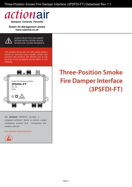
Three-Position Smoke Fire Damper Interface (3PSFDI-FT) - Actionair
Three-Position Smoke Fire Damper Interface (3PSFDI-FT) - Actionair
Three-Position Smoke Fire Damper Interface (3PSFDI-FT) - Actionair

Create successful ePaper yourself
Turn your PDF publications into a flip-book with our unique Google optimized e-Paper software.
<strong>Three</strong>-<strong>Position</strong> Release: 1.1 <strong>Smoke</strong> <strong>Fire</strong> <strong>Damper</strong> <strong>Interface</strong> (<strong>3PSFDI</strong>-<strong>FT</strong>) Datasheet Rev <strong>3PSFDI</strong>-<strong>FT</strong> 1.1 Datasheet<br />
Always READ this document<br />
BEFORE INSTALLATION. Please<br />
Retain for future reference.<br />
This product forms part of a life safety system.<br />
Failure to correctly store, handle, install, and<br />
maintain this product will directly put at risk<br />
the lives of the occupants and the fabric of the<br />
building.<br />
<strong>Smoke</strong> <strong>Fire</strong> <strong>Damper</strong> <strong>Interface</strong><br />
<strong>3PSFDI</strong>-<strong>FT</strong><br />
24 V<br />
25 VA ~<br />
<strong>Three</strong>-<strong>Position</strong> <strong>Smoke</strong><br />
<strong>Fire</strong> <strong>Damper</strong> <strong>Interface</strong><br />
(<strong>3PSFDI</strong>-<strong>FT</strong>)<br />
The <strong>Actionair</strong> <strong>3PSFDI</strong>-<strong>FT</strong> provides a<br />
complete LonWorks® device to control a single<br />
modulating actuator that incorporates two<br />
auxiliary switches.<br />
ELECTROSTATIC SENSITIVE DEVICE<br />
PAGE 1
<strong>Three</strong>-<strong>Position</strong> <strong>Smoke</strong> <strong>Fire</strong> <strong>Damper</strong> <strong>Interface</strong> (<strong>3PSFDI</strong>-<strong>FT</strong>) Datasheet Rev 1.1<br />
Release: Se: 1.1<br />
<strong>3PSFDI</strong>-<strong>FT</strong> Datasheet<br />
Dimensions and Mounting<br />
Mounting Diagram<br />
The compact and robust design of the enclosure<br />
allows the unit to be mounted to a duct, block wall,<br />
or stud wall.<br />
200<br />
75<br />
aprox 25<br />
Ensure the unit is located close enough to the<br />
actuator it is controlling/monitoring. Normally<br />
actuator leads are 1 m in length. Ensure the unit is<br />
accessible for future maintenance purposes.<br />
Please note:<br />
• Unused cable entries should be sealed with<br />
blind washers.<br />
• Do not drill the enclosure as this will affect its<br />
IP rating.<br />
160<br />
60 15<br />
aprox 25<br />
120<br />
Four mounting holes<br />
Ø 6mm for mounting<br />
with suitable screws<br />
depending on whether<br />
mounting to a duct,<br />
block wall or stud wall.<br />
Dimensions in mm.<br />
220<br />
10<br />
PAGE 2
<strong>Three</strong>-<strong>Position</strong> <strong>Smoke</strong> <strong>Fire</strong> <strong>Damper</strong> <strong>Interface</strong> (<strong>3PSFDI</strong>-<strong>FT</strong>) Datasheet Rev 1.1<br />
Release: Se: 1.1<br />
<strong>3PSFDI</strong>-<strong>FT</strong> Datasheet<br />
Preparation<br />
• Only trained and qualified personnel should<br />
be allowed to install, replace, or service<br />
this equipment. Installation should be in<br />
accordance with the relevant local safety<br />
standards.<br />
• The connectors can accommodate cable<br />
diameters up to 2.5 mm 2 . It is recommended<br />
that all wires are crimped to ease installation<br />
and replacement of the product.<br />
Wiring Diagram <strong>3PSFDI</strong>-<strong>FT</strong> in enclosure without lid<br />
Modulating<br />
actuator<br />
Thermal<br />
Trip<br />
LOCAL Mode<br />
U1<br />
GND<br />
To BMS<br />
Y1<br />
GND From BMS<br />
Installation<br />
1. Disconnect the local supply before<br />
commencing any work on the unit.<br />
2. Wire the unit in accordance with the wiring<br />
diagram shown across. If the actuator is<br />
located more than 5 m from the unit, then<br />
contact Safegard Systems for technical<br />
assistance.<br />
3. It is recommended that the network cables<br />
are not run alongside any high voltage or high<br />
frequency sources. Network cables should not<br />
be mixed on an individual network as they<br />
have very different electrical characteristics<br />
and could render the unit unreliable.<br />
F1<br />
+ -<br />
C1<br />
POWER IN<br />
ACTUATOR DRIVE ACT AUX SWITCHES LOCAL CONTROL<br />
C2 C3 C4<br />
24V GND Y U<br />
Status LEDs<br />
S6 S4 S2 S1 U1 GND Y1 GND<br />
Green<br />
Red<br />
Yellow<br />
Blue<br />
Setpoint<br />
potentiometer<br />
GND<br />
C6<br />
NETWORK<br />
GND<br />
C5<br />
NETWORK<br />
Learn Switch<br />
Learn LED<br />
Power LED<br />
Service LED<br />
Service Pin<br />
4. Once the wiring is complete, apply power to<br />
the unit.<br />
5. The unit is now ready to be configured using<br />
the Safegard Builder installation tool.<br />
C1<br />
+ -<br />
+ -<br />
OR<br />
C1<br />
+ -<br />
24V AC<br />
Network<br />
Network<br />
Replacement Fuse<br />
2 A time-lag fuse (see F1 on wiring diagram).<br />
Suggested replacement: Littelfuse 215 series.<br />
24V DC<br />
Connector Description<br />
C1-1 24 V power<br />
C1-2 GND<br />
C2-4 Actuator 24 V<br />
C2-3 Actuator GND<br />
C2-2 Actuator Y signal<br />
C2-1 Actuator U signal<br />
C3-4 S6<br />
C3-3 S4<br />
C3-2 S2<br />
C3-1 S1<br />
Connector Description<br />
C4-4 U1 to BMS<br />
C4-3 GND to BMS<br />
C4-2 Y1 from BMS<br />
C4-1 GND from BMS<br />
C5-1 GND (do not connect)<br />
C5-2 Network<br />
C5-3 Network<br />
C6-1 GND (do not connect)<br />
C6-2 Network<br />
C6-3 Network<br />
PAGE 3
<strong>Three</strong>-<strong>Position</strong> <strong>Smoke</strong> <strong>Fire</strong> <strong>Damper</strong> <strong>Interface</strong> (<strong>3PSFDI</strong>-<strong>FT</strong>) Datasheet Rev 1.1<br />
Release: Se: 1.1<br />
<strong>3PSFDI</strong>-<strong>FT</strong> Datasheet<br />
Auto Mode<br />
Modulating<br />
actuator<br />
Thermal<br />
Trip<br />
Status LEDs<br />
Function Green Red Yellow Blue<br />
Open On Off<br />
Closed Off On<br />
Balanced On On<br />
Travelling Flashing Flashing<br />
Fault<br />
Flashing<br />
Ping<br />
one-shot<br />
Offline On On On On<br />
Wink function: Service LED (yellow) flashes for 5s<br />
ACTUATOR DRIVE ACT AUX SWITCHES<br />
C2 C3 C4<br />
F1<br />
24V GND Y U<br />
S6 S4 S2 S1 U1 GND Y1 GND<br />
Status LEDs<br />
Green<br />
Red<br />
Yellow<br />
Blue<br />
Setpoint<br />
potentiometer<br />
+ -<br />
C1<br />
POWER IN<br />
GND<br />
C6<br />
NETWORK<br />
GND<br />
C5<br />
NETWORK<br />
Network<br />
Network<br />
<strong>Smoke</strong><br />
control<br />
system<br />
PAGE 4
<strong>Three</strong>-<strong>Position</strong> Release: Se: 1.1<br />
<strong>Smoke</strong> <strong>Fire</strong> <strong>Damper</strong> <strong>Interface</strong> (<strong>3PSFDI</strong>-<strong>FT</strong>) Datasheet Rev <strong>3PSFDI</strong>-<strong>FT</strong> 1.1 Datasheet<br />
Learn Mode<br />
Modulating<br />
actuator<br />
Thermal<br />
Trip<br />
Status LEDs<br />
Function Green Red Yellow<br />
Learn On/Off On/Off<br />
ACTUATOR DRIVE ACT AUX SWITCHES<br />
C2 C3 C4<br />
F1<br />
24V GND Y U<br />
S6 S4 S2 S1 U1 GND Y1 GND<br />
Status LEDs<br />
Green<br />
Red<br />
Yellow<br />
Blue<br />
Setpoint<br />
potentiometer<br />
1<br />
2<br />
Learn Switch on<br />
90°<br />
0°<br />
The Learn LED illuminates when<br />
the actuator is within 2º of the setpoint<br />
3<br />
Service Pin<br />
(hold for 1sec)<br />
+ -<br />
C1<br />
POWER IN<br />
GND<br />
C6<br />
NETWORK<br />
GND<br />
C5<br />
NETWORK<br />
4<br />
Learn Switch off<br />
Network<br />
Network<br />
<strong>Smoke</strong><br />
control<br />
system<br />
PAGE 5
<strong>Three</strong>-<strong>Position</strong> <strong>Smoke</strong> <strong>Fire</strong> <strong>Damper</strong> <strong>Interface</strong> (<strong>3PSFDI</strong>-<strong>FT</strong>) Datasheet Rev 1.1<br />
Release: Se: 1.1<br />
<strong>3PSFDI</strong>-<strong>FT</strong> Datasheet<br />
Local Mode<br />
Modulating<br />
actuator<br />
Thermal<br />
Trip<br />
Status LEDs<br />
Function Green Red Yellow<br />
Local<br />
on<br />
BUILDING<br />
MANAGEMENT<br />
SYSTEM<br />
ACTUATOR DRIVE ACT AUX SWITCHES LOCAL CONTROL<br />
C2 C3 C4<br />
F1<br />
24V GND Y U<br />
S6 S4 S2 S1 U1 GND Y1 GND<br />
Status LEDs<br />
Green<br />
Red<br />
Yellow<br />
Blue<br />
Setpoint<br />
potentiometer<br />
+ -<br />
C1<br />
POWER IN<br />
GND<br />
C6<br />
NETWORK<br />
GND<br />
C5<br />
NETWORK<br />
Network<br />
Network<br />
<strong>Smoke</strong><br />
control<br />
system<br />
PAGE 6
<strong>Three</strong>-<strong>Position</strong> <strong>Smoke</strong> <strong>Fire</strong> <strong>Damper</strong> <strong>Interface</strong> (<strong>3PSFDI</strong>-<strong>FT</strong>) Datasheet Rev 1.1<br />
Release: Se: 1.1<br />
<strong>3PSFDI</strong>-<strong>FT</strong> Datasheet<br />
Specification<br />
LonWorks<br />
Neuron chip <strong>FT</strong> 5000<br />
Transceiver type<br />
Service functions<br />
N<br />
Supply<br />
Input voltage<br />
Max power consumption<br />
Output<br />
Contact type<br />
Max switched load<br />
Inputs<br />
Contact type<br />
Sense current<br />
<strong>FT</strong>-X2<br />
Service Pin, Service LED, and<br />
neuron ID self-adhesive tag<br />
(24 ± 4.8) V AC, 50 Hz<br />
(24 ± 2.4) V DC<br />
1.3 W<br />
SPST mechanical<br />
relay contact<br />
25 VA<br />
non-isolated dry contacts<br />
10 mA<br />
Environmental<br />
Operating temperature -5 °C to 70 °C<br />
Storage temperature -20 °C to 70 °C<br />
Humidity 25 % RH to 90 % RH at 70 °C<br />
Maximum altitude<br />
Conformance<br />
emc<br />
Agency listings<br />
Enclosure<br />
Material<br />
2000 m<br />
en 60730-1:00+A1:04+A2:08+A16:07<br />
CE<br />
IP rating IP 54<br />
Flammability ul 94V-0<br />
Pollution category 2<br />
Dimensions (excl glands)<br />
Dimensions (incl glands)<br />
aBS base with polycarbonate lid<br />
200 mm x 120 mm x 75 mm<br />
(L x W x D)<br />
200 mm x 170 mm x 75 mm<br />
(L x W x D)<br />
complies with european standards<br />
WARNING: The responsible body shall be made aware that, if the equipment is used in a manner not specified by the<br />
manufacturer, the protection provided by the equipment may be impaired.<br />
lonworks,<br />
lonmark, lonmaker and the 3150 are trademarks of echelon corporation registered in the united States and other<br />
countries. all other trademarks are acknowledged.<br />
Ruskin Air Management Limited<br />
South Street, Whitstable, Kent<br />
CT5 3DU England.<br />
Tel: 01227 276100<br />
Fax: 01227 264262<br />
Email: sales@actionair.co.uk<br />
Website: www.actionair.co.uk