Actionair Installati..
Actionair Installati..
Actionair Installati..

You also want an ePaper? Increase the reach of your titles
YUMPU automatically turns print PDFs into web optimized ePapers that Google loves.
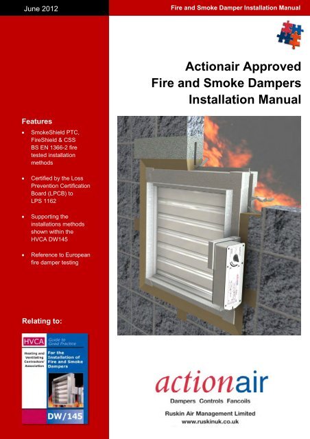
June 2012<br />
Fire and Smoke Damper <strong>Installati</strong>on Manual<br />
<strong>Actionair</strong> Approved<br />
Fire and Smoke Dampers<br />
<strong>Installati</strong>on Manual<br />
Features<br />
<br />
SmokeShield PTC,<br />
FireShield & CSS<br />
BS EN 1366-2 fire<br />
tested installation<br />
methods<br />
<br />
<br />
<br />
Certified by the Loss<br />
Prevention Certification<br />
Board (LPCB) to<br />
LPS 1162<br />
Supporting the<br />
installations methods<br />
shown within the<br />
HVCA DW145<br />
Reference to European<br />
fire damper testing<br />
Relating to:
www.ruskinuk.co.uk<br />
INTRODUCTION<br />
Over the years there have been lots of attempts to provide generic information with regard to damper<br />
installations. These have come about from the old “GLC” regulations, which were adopted by industry<br />
bodies and supported by test houses and trade associations. However, with the publication of BS EN<br />
1366-2:1999, the European standard for the fire testing of dampers (where no specific standard<br />
existed before), and revisions to the guidance from the UK regulators (Approved Document B (ADB)),<br />
it has been increasingly difficult for manufacturers to provide such generic information.<br />
The method of installation is important, as it is the interface between the damper and the supporting<br />
construction. This plays a significant role on the final result of the test and thus the “classification” of<br />
the damper. Manufacturers products cannot be assumed to perform the same in every installation and<br />
more importantly different manufacturers products will have their own performance classification.<br />
The classification states the performance of the fire damper, for the installation method, as a time.<br />
This will indicate the suitability of the damper in that particular installation method for its Integrity (E)<br />
and, if available for the specific product, the damper leakage to achieve a smoke classification (S).<br />
The Smoke Shield & CSS ranges, both have E and ES classifications, and the Fire Shield has E<br />
classification, but the performance in time can vary with differing methods of installation. For an<br />
overview please see summary pages.<br />
Therefore manufacturers must provide specific data as it represents what has been tested or<br />
assessed. In the following pages you will find our installations fully described, along with drawings.<br />
Also referenced are our test reports, which are available from the <strong>Actionair</strong> sales office.<br />
Previously assessments to meet the requirements of BS476 were most common, these are not easy<br />
to come by with regard to the BS EN 1366-2:1999 test methods for the reasons described above. It is<br />
important to check that your proposed installation method meets one of those described. You should<br />
also review the guidance given in the HVAC document DW145 that outlines the industry standard for<br />
the installation of dampers.<br />
Ruskin Air Management Limited is not able to approve specific installations that vary from those<br />
tested and described herein. You may seek assessment from bodies such as BRE/LPC or WFR who<br />
will require fully dimensioned drawings with material details for your proposed installation, together<br />
with any copies of our test reports for the product.<br />
Over and above product testing, Ruskin Air Management Limited products are third party certificated.<br />
This means added confidence. In addition to full ISO 9001:2008 quality assurance, the notified body<br />
also checks the products to ensure that they are still being manufactured as tested or assessed, such<br />
that the components are traceable back to the fire tests, assessments and product design files. The<br />
Loss Prevention Certification Board (LPCB) performs our QA and product audits.<br />
While Ruskin Air Management Limited has undertaken extensive testing, it is not complete and we<br />
continue to carry out tests that reflect industry practices and supplement the tests published here.<br />
These will be added in further versions of this document as and when the details become available.<br />
We also have our Damper Application Guide, our extensive website, the support of our External Sales<br />
Team and our Whitstable Sales and Technical Offices, all ready to give additional details and<br />
guidance.<br />
The regulatory requirements have changed and are changing, please use this document along with<br />
DW145 to make sure your design and installation meets the current requirements and remember, fire<br />
dampers are life safety products.<br />
Kevin Munson<br />
Managing Director<br />
September 2011<br />
<strong>Actionair</strong> Damper<br />
Application Guide<br />
<strong>Actionair</strong> website<br />
1
www.ruskinuk.co.uk<br />
BACKGROUND<br />
Requirements<br />
The Building Regulations - this is the law.<br />
Approved Documents - These are published guides described as “practical guidance” to meeting the<br />
requirements of the building regulations.<br />
British and European Standards - These are published standards on product definition, testing and<br />
classification, system requirements, recommendations and maintenance.<br />
Certification Standards - These are standards published by certification bodies to ensure products have<br />
undergone the necessary third party testing. They are then used by a notified body as the basis to ensure that<br />
products remain as tested, and that changes are re-tested or assessed by qualified personnel.<br />
There are further documents available, which are referenced in ADB that give details to designers to allow the<br />
consideration of business risk issues from smoke and fire – i.e. financial loss, and is sponsored by insurers, to<br />
help assess premiums.<br />
Building Regulations<br />
By following the instructions in the approved documents you will fulfil the requirements of the regulations.<br />
If you can prove (with evidence or calculation) that another method is satisfactory you may use this - this is<br />
called fire engineering, but must be approved by a Building Control Authority (BCA) before use.<br />
England & Wales<br />
The document that gives an interpretation of the rules for Fire Safety is Approved Document B (ADB). This is<br />
available as a free download from the Planning Portal website.<br />
It has been republished dated 2006 and will be applicable to all projects submitted for planning approval from<br />
April 2007.<br />
It recommends the use of products meeting independent certification schemes, such schemes certifying<br />
compliance with the requirements of a recognised document, which is appropriate to the purpose for which the<br />
material is to be used. In addition to life safety it mentions the protection of property, including the building itself,<br />
stating that this may require additional measures, and insurers may seek their own higher standards, before<br />
accepting the insurance risk.<br />
There have been a considerable number of changes with regard to fire dampers. They now have their own<br />
section giving very specific guidance.<br />
Paragraphs 5.46 to 5.48 "Mechanical ventilation and air conditioning systems” state that fire dampers protecting<br />
escape routes should respond to a smoke detector or suitable fire detection system, noting that a fusible link<br />
alone is not acceptable and this implies that some type of actuator be used. The purpose of this is to ensure<br />
early closure to prevent passage of smoke. It also states that a damper with an ES classification may be used.<br />
The reader is then directed to paragraph 10.15.<br />
Paragraphs 10.11 to 10.15 "Fire dampers" are more specific and also require actuation for fire dampers in<br />
buildings where there are levels of sleeping risk. The note that “fusible link only dampers being unsuitable to<br />
protect escape routes” is repeated together with the suitability of an ES rated product. 10.15 then explains the<br />
requirements for E and ES classifications. To achieve any classification fire dampers must be tested to BS1366-<br />
2:1999. A Fire Damper has an E (Integrity) classification. A Leakage Rated Fire Damper has an E (Integrity) and<br />
an S (Reduced leakage) classification.<br />
SmokeShield dampers fulfil the ES requirements for escape routes and areas with sleeping risk. FireShield fulfil<br />
the E requirements and can be used in all other areas for run out ducting etc.<br />
ADB states that dampers should be mounted within the structure that they are seeking to protect and should be<br />
installed as tested.<br />
Finally there is a statement saying that fire dampers tested only to BS476 may only be appropriate for fan off<br />
situations.<br />
For the purposes of application, what are presently known as “combination fire and smoke dampers”, providing<br />
that they have an ES classification to BS EN 13501-3:2005, now termed “leakage rated fire dampers”, actuated<br />
via a smoke detection system will fulfil the requirements for the protection of escape routes and the protection of<br />
areas with sleeping risk. Curtain fire dampers and other dampers having an E classification to BS EN 13501-<br />
3:2005 will fulfil the general requirements for all other applications/areas.<br />
Scotland<br />
These exist as technical standards (AMD’s). They give very similar guidance to ADB. They already include<br />
direct references to the application of European standards. They are available as a free download from the<br />
Scottish Executive website.<br />
2
www.ruskinuk.co.uk<br />
Standards<br />
Fire damper Standards<br />
BS EN 1366-2:1999 (Test standard) gives requirements for testing dampers to the standard time/temperature<br />
curve with a requirement to close within two minutes of the start of the test. After closure a 300Pa pressure<br />
differential is applied to the damper and the damper leakage (corrected to 20°C) is recorded throughout the rest<br />
of the test. The largest size of damper to be offered for sale must be fire tested. Pass and fail criteria is included<br />
in the standard.<br />
Integrity – E – the damper must leak no more than 360m³/hr/m² at any point during the test.<br />
Optional Integrity and Leakage – ES – the damper must leak no more than 200m³/hr/m² at any point<br />
during the fire test. This also applies to the largest and smallest size of damper to be offered for sale at<br />
ambient temperatures for the ES criteria to be applicable.<br />
Optional Insulation – I – insulation rating - not required by legislation for dampers in the UK.<br />
BS EN 13501-3:2005 (Classification Standard) – states times and performance to enable the classification of<br />
fire dampers (E, ES and I requirements)<br />
BS EN 15650:2010 (Product standard) contains the basic performance and requirements for fire dampers<br />
System design and related standards<br />
BS 9999:2008 Code of practice for fire safety in the design, management and use of buildingsprovides<br />
guidance on the ongoing management of fire safety in a building throughout the entire life cycle of the<br />
building, including guidance for designers to ensure that the overall design of a building assists and enhances<br />
the management of fire safety. It can be used as a tool for assessing existing buildings, although fundamental<br />
change in line with the guidelines might well be limited or not practicable.<br />
The standard builds on government guidance to legislative requirements, providing an advanced approach to<br />
fire safety in the design, management and use of buildings. It promotes a more flexible approach to fire safety<br />
design through use of structured risk-based design where designers can take account of varying human factors.<br />
BS EN 12101-6:2005 Smoke and heat control systems. Specification for pressure differential systemsgives<br />
test procedures for the systems used, as well as describing relevant, and critical, features of the<br />
installation and commissioning procedures needed to implement the calculated design in a building. It covers<br />
systems intended to protect means of escape such as stairwells, corridors and lobbies, as well as systems<br />
intended to provide a protected fire fighting bridgehead for the Fire Services.<br />
Certification Standards<br />
LPS 1162 is a typical product certification standard. It contains all the tests that the Loss Prevention Certification<br />
Board (LPCB) requires the product to undergo, before certification may be offered. It also states that to meet it,<br />
a company must have full BS EN ISO 9001 accreditation. The LPCB visit the factory at least once a year to<br />
confirm by measurement that the certificated products maintain all the tested dimensions, and confirm that the<br />
products still comply with any assessments that may have been made. Using certificated products mean less<br />
time needs to be taken checking up that products meet the required standards, as a third party is making sure<br />
that this is the case.<br />
Extended Fields of Application (Assessments)<br />
Under BS EN 1366-2 etc. specific documents are being drafted for the extended field of application for all<br />
products. It is becoming clear that assessments for small component changes and the use of units smaller than<br />
those tested are allowable. However the use of methods of installation other than that tested will lead to<br />
problems, with assessments being difficult to acquire. The reason for this is the fact that the test is passed or<br />
failed based on the leakage of the unit during the test, as well as any failure at the boundary between the<br />
damper and the supporting construction. The damper closing is just the start of the test.<br />
The laboratories are unwilling to state that a change in building in method will not affect the leakage<br />
performance.<br />
Previously, under the BS 476 ad-hoc testing, assessments were forthcoming with respect to installation, this<br />
was because the test pass or fail criteria were purely mechanical with gap gauges etc, not leakage<br />
measurement.<br />
3
www.ruskinuk.co.uk<br />
4
www.ruskinuk.co.uk<br />
5
www.ruskinuk.co.uk<br />
6
www.ruskinuk.co.uk<br />
CE Marking and Third Party Certification<br />
Certain European member states, including the UK & Ireland, have until now chosen not to make CE marking<br />
mandatory for products sold within their boundaries, despite the fact that under the Construction Products<br />
Directive (CPD), it has been mandatory to 'CE' mark construction products placed on the European market.<br />
In 2011, the CPD was replaced by the Construction Products Regulation (CPR), which does not allow any<br />
member state to 'opt out' of mandatory CE marking. Consequently, from 1 st July 2013, the CPR states that all<br />
products that fall within scope of Harmonised European Standards (hENs) will have to be CE marked.<br />
The installation methods contained within this manual are third party tested or assessed, and certified, by our<br />
Notified Body (LPCB), as prescribed within the CPR.<br />
The message is simple: from 1 st July 2013, ensure that every product specified is properly certified (CE marked)<br />
and installed correctly. It is also important to be wary of, or even avoid, products that use phrases such as<br />
'designed to meet' and 'complies with'. The key word to look out for is 'certification'.<br />
INSTALLATION METHODS<br />
The following sections deal with the installation methods. There are dimensional drawings, and a detailed<br />
description of each method.<br />
In each case the classifications are shown, together with the fire test reference. Fire test reports are available in<br />
full from the <strong>Actionair</strong> sales office. These are large documents and we are not permitted to abridge them. They<br />
are available in pdf document format.<br />
Alternative partition systems to those shown within this installation manual can be used if they have been shown<br />
by test to have at least the same fire resistance when tested to BS EN 1364-1:1999 as is required of the<br />
damper. If the partition system has been successfully tested without stone mineral wool, it does not have to be<br />
used in practice when only considering the fire performance of the complete system. The mineral wool may still<br />
be needed for other reasons, e.g. acoustic performance.<br />
The mortar used in the tests shown within this installation manual had a standard sand/cement mix in the ratio<br />
of 4:1. Alternative fire resisting refractory mortars may be used providing that they have been tested in<br />
accordance with BS EN 1366-3:2009 for the required period when installed around the damper.<br />
The ablative batt penetration sealing systems used in the tests shown within this installation manual was 60mm<br />
thick Rockwool Ablative Coated Batt. Alternative batt penetration sealing systems may be used providing that<br />
they have been tested in accordance with BS EN 1366-3:2009 for the required period when installed around the<br />
damper.<br />
DW145<br />
Guide to good practice, for the installation of fire and smoke dampers<br />
The DW145 guide is intended to highlight and clarify the important aspects of fire and smoke barrier / damper<br />
installation, including the responsibilities of all parties involved in the overall sequence from system specification<br />
through to a compliant installation. Emphasis is placed on the need for all parties to work as a team by<br />
recognising not only their individual responsibilities, but also those of all other parties in achieving this goal.<br />
The guidance only relates to the installation of fire dampers and leakage rated fire smoke dampers as used in<br />
ventilation systems to maintain fire compartments and / or protect means of escape from buildings and does not<br />
cover the installation of powered smoke control dampers.<br />
The importance of installing damper arrangements that have been selected / specified by the system designer<br />
and that have been successfully fire tested by an independent body on behalf of the damper manufacturer is<br />
emphasised throughout the guide.<br />
Communication between team members and the need for consistency in both design and approach are key<br />
factors in achieving a compliant design. The guide recommends that check lists are utilised and adapted to suit<br />
the specific requirements of an individual project. Typical check sheet are included in appendix E of the guide<br />
and we have developed check lists for inspection and handover (E3 in the guide) specifically for our dampers.<br />
These can be downloaded from our web site for the installations shown in this installation guide.<br />
7
www.ruskinuk.co.uk<br />
DW145 Inspection and handover check sheet<br />
Ruskin Air Management<br />
Damper <strong>Installati</strong>on Certificate<br />
The installer must complete this installation certificate when installing fire and smoke dampers. A separate certificate<br />
must be completed for each individual fire and smoke damper.<br />
No. Question Action Tick<br />
1 Are the dampers the correct type<br />
Confirm damper is correct type<br />
E.g. SmokeShield, CSS or Fire Shield<br />
2 Are the dampers located correctly<br />
The damper location is to be checked against the<br />
installation drawings/details<br />
3 Are the dampers correctly identified<br />
Unique system i.d. to be clearly indicated on the damper<br />
or other agreed location.<br />
4<br />
Have supports for both the damper and<br />
the adjacent ductwork been installed in<br />
5<br />
6<br />
7<br />
8<br />
9<br />
10<br />
11<br />
12<br />
13<br />
14<br />
accordance with the approved manner<br />
Are the dampers fitted in the correct<br />
orientation<br />
Is access through the ductwork, to the<br />
damper unobstructed<br />
Has the space around the damper and<br />
within the opening been left clear and<br />
not been used for other services<br />
Using the access opening provided, are<br />
the damper blades in the open position<br />
Has the damper been checked for<br />
internal cleanliness, free from damage<br />
and that vertical casings in particular are<br />
free from debris<br />
Has the damper been released to<br />
simulate operation of the thermal<br />
release (Damper drop test)<br />
Have the damper blades been re-set<br />
following drop test and the access panel<br />
replaced<br />
At the time of damper handover, is the<br />
fire barrier and penetration seal<br />
complete<br />
Is the damper installation complete and<br />
available for handover prior to system<br />
commissioning<br />
Is the completed handover register<br />
cross-referenced back to the<br />
identification codes listed in the system<br />
designer’s damper schedule<br />
Confirm the damper installed the correct way up and<br />
relative to airflow and or access.<br />
Unobstructed space should be provided for safe access<br />
to the damper. This must include access through ceiling<br />
voids and adjacent services. Damper installer to advise<br />
the system designer if problems are foreseen.<br />
Other services within the installation opening will<br />
invalidate the installation method. Damper installer to<br />
advise the lead contractor if problems are foreseen.<br />
Check position of damper blades.<br />
With the damper in the closed position, inspect for<br />
damage.<br />
Ensure damper operation is free from interference.<br />
After re-setting the damper, check the position shown on<br />
the blade position indicator is correct.<br />
Damper installer to record on the handover register if any<br />
following trades are still to complete their activities.<br />
Obtain the relevant acceptance of the damper installation<br />
from the CDM coordinator.<br />
This certificate applies only to Ruskin Air Management products.<br />
Damper Unique System i.d. ______________________________________________________________________<br />
Name of installation location: _____________________________________________________________________<br />
Address: _____________________________________________________________________________________<br />
<strong>Installati</strong>on location identification (section/floor/room): __________________________________________________<br />
Damper product type: ___________________________________________________________________________<br />
Release fuse temperature: _______________________________________________________________________<br />
Notes/Considerations: __________________________________________________________________________<br />
_____________________________________________________________________________________________<br />
_____________________________________________________________________________________________<br />
Installed by: -<br />
Company Name: _______________________________________________________________________________<br />
Address: _____________________________________________________________________________________<br />
Company Telephone N o : _________________________________________________________________________<br />
Installers Name(s): _____________________________________________________________________________<br />
Installers Telephone N o : _________________________________________________________________________<br />
Date of installation: _____________________________________________________________________________<br />
It is herby verified that the damper detailed above has been installed and tested according to the manufactures<br />
recommendations:<br />
Installers signature: _________________________________________ Date: ______________________________<br />
8
www.ruskinuk.co.uk<br />
Horizontal in floor slab HEVAC / HVCA <strong>Installati</strong>on frame (IF)<br />
Health and safety<br />
This process must be undertaken by competent persons. More than one person may be required to ensure the<br />
safe handling of large dampers and other materials.<br />
Use must be made of access equipment to ensure unsafe practices are not used to approach walls or difficult<br />
access areas.<br />
Standard site PPE should be used (minimum steel toe cap boots, hard hat); together with any protective<br />
eyewear, gloves and masks, when drilling or cutting is being undertaken. The latter should also be used when<br />
handing the wall construction materials, as defined by the material suppliers. If loud equipment is being used,<br />
hearing protection should be used.<br />
All waste materials should be collected and disposed of as defined by the relevant supplier.<br />
Damper installation method<br />
1) Measure the positions of the building ties on the HEVAC frame<br />
2) Mark up the inside edges of the hole in the slab to give positions that match to the building ties. Drill into the<br />
floor slab and fit stud anchors (or similar) – leaving them protruding into the opening<br />
3) Turn out the building ties on the damper and offer the damper into position.<br />
4) Using steel wire (min 1.5mm), wrap this round the building ties and the stud anchors to hold the damper in<br />
position.<br />
(Note: This will also maintain the quality of the link between the damper, the infill mortar and the floor slab should a fire occur)<br />
5) Shutter beneath the damper (if required) and add mortar from the top of the slab and infill to the HEVAC<br />
frame. Take care not to infill past the line on the interface shroud if the motor is to be fitted above the slab.<br />
6) When the mortar is firm remove the shuttering (if applied) and infill with more mortar to the HEVAC frame<br />
from below the slab. Take care not to infill past the line on the interface shroud if the motor is to be fitted<br />
below the slab.<br />
Actuator fitting (If required)<br />
1) The control mode/actuator should then be fitted using the instructions supplied with it.<br />
2) Using the supplied drilling template, drill into the ductwork and fit the Electrical Thermal Release (ETR) into<br />
the duct.<br />
3) A special feature of the <strong>Actionair</strong> SmokeShield modes is that they may be adjusted from pointing straight<br />
out along the duct (standard configuration) through 90° to point either up or down if required.<br />
4) The mode should be wired into the system using the site wiring detail, plus the details shown on the label.<br />
Note: If the mode/actuator fitting instructions are missing, please contact the <strong>Actionair</strong> sales office for a new copy.<br />
Commissioning<br />
The procedure detailed under periodic maintenance should be followed<br />
Periodic maintenance<br />
As detailed in BS 9999:2008<br />
1) For dampers this is at least once per year for units with spring operation.<br />
2) Units operating in dust laden atmospheres, should be checked more often to suit the severity of the system<br />
3) Units associated with systems may be required to be checked, as part of the system, as often as once per<br />
week or month to ensure ongoing confidence in the life safety system. This may be seen as analogous to<br />
fire alarm systems.<br />
Procedure<br />
1) The units should be carefully inspected and cleaned of dust and debris<br />
2) The units should then be lubricated with a light oil, by wiping this over all the surfaces<br />
3) The mode should be operated to ensure that it is moving the blades from open to closed and the reverse.<br />
4) If the micro switches (in the mode) are being used, it should be checked that they are actually indicating that<br />
the blades are open or closed. This is done by running a cycle and checking both the blades (open and<br />
closed) and the indication that the micro switches are feeding back to.<br />
9
www.ruskinuk.co.uk<br />
AAF10700 (A)<br />
INSTALLATION DETAIL<br />
IF YOUR PROPOSED<br />
INSTALLATION DETAIL DIFFERS<br />
FROM THAT SHOWN, YOU MUST<br />
DISCUSS THIS WITH THE<br />
BUILDING CONTROL AUTHORITY<br />
(BCA), REFERENCING THIS<br />
DOCUMENT AND THE<br />
ASSOCIATED FIRE TESTS,<br />
ASSESSMENTS AND OTHER<br />
DOCUMENTS SHOWN BELOW.<br />
DEVIATION FROM THIS DRAWING<br />
REQUIRES THE APPROVAL OF<br />
THE RELEVANT AUTHORITY.<br />
SMOKE SHIELD DAMPER<br />
BUILDING TIES<br />
BENT OUTWARDS<br />
INSTALLATION FRAME<br />
A<br />
INSTALLATION FRAME<br />
UPSTAND FLANGE<br />
4:1 SAND : CONCRETE MIX MORTAR<br />
AERATED CONCRETE SLAB<br />
10mm STUD ANCHORS<br />
APPLICABLE TEST<br />
REPORT − BS EN1366−2<br />
BRE 231740<br />
ACTIONAIR REF: AA/F10700 (A)<br />
240 MINUTES<br />
FIRE RESISTANCE<br />
INTEGRITY<br />
120 MINUTES<br />
FIRE RESISTANCE<br />
INTEGRITY & LEAKAGE<br />
VIEW A<br />
(ALL ROUND DETAIL)<br />
CONNECTING DUCTWORK OMITTED FOR CLARITY<br />
15mm − 60mm ALL ROUND<br />
FROM THE INSTALLATION<br />
FRAME UPSTAND FLANGE<br />
TO THE APERTURE FACE<br />
10<br />
1.5mm STEEL WIRE SECURING<br />
DAMPER BUILDING TIES,<br />
TO STUD ANCHORS<br />
www.actionair.co.uk<br />
HORIZONTAL APPLICATION<br />
SMOKE SHIELD &<br />
INSTALLATION FRAME<br />
DAMPER SIZE RANGE (mm):<br />
200 x 200 TO 1000 x 1000
www.ruskinuk.co.uk<br />
AAF10701 (A)<br />
INSTALLATION DETAIL<br />
IF YOUR PROPOSED<br />
INSTALLATION DETAIL DIFFERS<br />
FROM THAT SHOWN, YOU MUST<br />
DISCUSS THIS WITH THE<br />
BUILDING CONTROL AUTHORITY<br />
(BCA), REFERENCING THIS<br />
DOCUMENT AND THE<br />
ASSOCIATED FIRE TESTS,<br />
ASSESSMENTS AND OTHER<br />
DOCUMENTS SHOWN BELOW.<br />
DEVIATION FROM THIS DRAWING<br />
REQUIRES THE APPROVAL OF<br />
THE RELEVANT AUTHORITY.<br />
INSTALLATION FRAME<br />
A<br />
INSTALLATION FRAME<br />
UPSTAND FLANGE<br />
APPLICABLE TEST<br />
REPORT − BS EN1366−2<br />
BRE 209934<br />
FIRE DAMPER<br />
4:1 SAND : CONCRETE MIX MORTAR<br />
ACTIONAIR REF: AA/F10701 (A)<br />
BUILDING TIES<br />
BENT OUTWARDS<br />
AERATED CONCRETE SLAB<br />
10mm STUD ANCHORS<br />
240 MINUTES<br />
FIRE RESISTANCE<br />
INTEGRITY<br />
VIEW A<br />
(ALL ROUND DETAIL)<br />
CONNECTING DUCTWORK OMITTED FOR CLARITY<br />
15mm − 60mm ALL ROUND<br />
FROM THE INSTALLATION<br />
FRAME UPSTAND FLANGE<br />
TO THE APERTURE FACE<br />
1.5mm STEEL WIRE SECURING<br />
DAMPER BUILDING TIES,<br />
TO STUD ANCHORS<br />
11<br />
BSEN13501−3 CLASSIFICATION<br />
E120 FIRE RESISTANCE − INTEGRITY<br />
www.actionair.co.uk<br />
HORIZONTAL APPLICATION<br />
FIRE SHIELD &<br />
INSTALLATION FRAME<br />
DAMPER SIZE RANGE (mm):<br />
100 x 100 TO 1250 x 1000
www.ruskinuk.co.uk<br />
Vertical in block work / Masonry wall HEVAC / HVCA <strong>Installati</strong>on frame (IF)<br />
Health and safety<br />
This process must be undertaken by competent persons. More than one person may be required to ensure the<br />
safe handling of large dampers and other materials.<br />
Use must be made of access equipment to ensure unsafe practices are not used to approach walls or difficult<br />
access areas.<br />
Standard site PPE should be used (minimum steel toe cap boots, hard hat); together with any protective<br />
eyewear, gloves and masks, when drilling or cutting is being undertaken. The latter should also be used when<br />
handing the wall construction materials, as defined by the material suppliers. If loud equipment is being used,<br />
hearing protection should be used.<br />
All waste materials should be collected and disposed of as defined by the relevant supplier.<br />
Damper installation method<br />
1) Measure the positions of the building ties on the HEVAC frame<br />
2) Mark up the lintel at the top of the hole in the wall to give positions that match to the building ties. Drill into<br />
the lintel and fit stud anchors or similar steel fixings (min 6.5mm x 60mm)<br />
3) Turn out the building ties on the damper and offer the damper into position, supporting from underneath with<br />
a block of wood or board, which will need to be removed when the mortar is in position.<br />
If 4 hour Integrity is required (E240) pockets in the wall will be required and wall ties turned out into them.<br />
4) Using a steel wire, wrap this round the building ties and the stud anchors in the lintel at the top, to hold the<br />
damper in position.<br />
(Note: This will also maintain the quality of the link between the damper, the infill mortar and the wall should a fire occur)<br />
5) Add mortar from both sides of the damper and infill to the HEVAC frame. Take care not to infill past the line<br />
on the interface shroud.<br />
Actuator fitting (If required)<br />
1) The control mode/actuator should then be fitted using the instructions supplied with it.<br />
2) Using the supplied drilling template, drill into the ductwork and fit the Electrical Thermal Release (ETR) into<br />
the duct (as good practice, this should be towards the top of the duct)<br />
3) A special feature of the <strong>Actionair</strong> SmokeShield modes is that they may be adjusted from pointing straight<br />
out along the duct (standard configuration) through 90° to point either up or down if required.<br />
4) The mode should be wired into the system using the site wiring detail, plus the details shown on the label.<br />
Note: If the mode/actuator fitting instructions are missing, please contact the <strong>Actionair</strong> sales office for a new copy.<br />
Commissioning<br />
The procedure detailed under periodic maintenance should be followed<br />
Periodic maintenance<br />
As detailed in BS 9999:2008<br />
1) For dampers this is at least once per year for units with spring operation.<br />
2) Units operating in dust laden atmospheres, should be checked more often to suit the severity of the system<br />
3) Units associated with systems may be required to be checked, as part of the system, as often as once per<br />
week or month to ensure ongoing confidence in the life safety system. This may be seen as analogous to<br />
fire alarm systems.<br />
Procedure<br />
1) The units should be carefully inspected and cleaned of dust and debris<br />
2) The units should then be lubricated with a light oil, by wiping this over all the surfaces<br />
3) The mode should be operated to ensure that it is moving the blades from open to closed and the reverse.<br />
4) If the micro switches (in the mode) are being used, it should be checked that they are actually indicating that<br />
the blades are open or closed. This is done by running a cycle and checking both the blades (open and<br />
closed) and the indication that the micro switches are feeding back to.<br />
12
www.ruskinuk.co.uk<br />
AAF10702 (A)<br />
INSTALLATION DETAIL<br />
15mm − 60mm ALL ROUND<br />
FROM THE INSTALLATION<br />
FRAME UPSTAND FLANGE<br />
TO THE APERTURE FACE<br />
LINTEL<br />
6.5mm (MIN) STEEL ANCHORS<br />
(TOP EDGE ONLY)<br />
4:1 SAND : CONCRETE MIX MORTAR<br />
1.5mm STEEL WIRE SECURING DAMPER<br />
BUILDING TIES, TO STUD ANCHORS<br />
(TOP EDGE ONLY)<br />
INSTALLATION FRAME<br />
SMOKE SHIELD DAMPER<br />
BUILDING TIES BENT<br />
OUT INTO WALL POCKETS<br />
ON SIDES & BOTTOM<br />
A<br />
INSTALLATION FRAME<br />
UPSTAND FLANGE<br />
IF YOUR PROPOSED<br />
INSTALLATION DETAIL DIFFERS<br />
FROM THAT SHOWN, YOU MUST<br />
DISCUSS THIS WITH THE<br />
BUILDING CONTROL AUTHORITY<br />
(BCA), REFERENCING THIS<br />
DOCUMENT AND THE<br />
ASSOCIATED FIRE TESTS,<br />
ASSESSMENTS AND OTHER<br />
DOCUMENTS SHOWN BELOW.<br />
DEVIATION FROM THIS DRAWING<br />
REQUIRES THE APPROVAL OF<br />
THE RELEVANT AUTHORITY.<br />
APPLICABLE TEST<br />
REPORT − BS EN1366−2<br />
BRE 259933<br />
ACTIONAIR REF: AA/F10702 (A)<br />
240 MINUTES<br />
FIRE RESISTANCE<br />
INTEGRITY<br />
VIEW A<br />
(ALL ROUND DETAIL)<br />
AERATED BLOCKWORK WALL<br />
120 MINUTES<br />
FIRE RESISTANCE<br />
INTEGRITY & LEAKAGE<br />
CONNECTING DUCTWORK OMITTED FOR CLARITY<br />
13<br />
ASSESSMENT BRE CC270714A<br />
120 MINUTES<br />
INTEGRITY & LEAKAGE<br />
WITHOUT THE USE OF WALL POCKETS<br />
www.actionair.co.uk<br />
VERTICAL APPLICATION<br />
SMOKE SHIELD &<br />
INSTALLATION FRAME<br />
DAMPER SIZE RANGE (mm):<br />
200 x 200 TO 1000 x 1000
www.ruskinuk.co.uk<br />
AAF10703 (A)<br />
INSTALLATION DETAIL<br />
LINTEL<br />
6.5mm (MIN) STEEL ANCHORS<br />
(TOP EDGE ONLY)<br />
INSTALLATION FRAME<br />
UPSTAND FLANGE<br />
A<br />
IF YOUR PROPOSED<br />
INSTALLATION DETAIL DIFFERS<br />
FROM THAT SHOWN, YOU MUST<br />
DISCUSS THIS WITH THE<br />
BUILDING CONTROL AUTHORITY<br />
(BCA), REFERENCING THIS<br />
DOCUMENT AND THE<br />
ASSOCIATED FIRE TESTS,<br />
ASSESSMENTS AND OTHER<br />
DOCUMENTS SHOWN BELOW.<br />
DEVIATION FROM THIS DRAWING<br />
REQUIRES THE APPROVAL OF<br />
THE RELEVANT AUTHORITY.<br />
15mm − 60mm ALL ROUND<br />
FROM THE INSTALLATION<br />
FRAME UPSTAND FLANGE<br />
TO THE APERTURE FACE<br />
4:1 SAND : CONCRETE<br />
MIX MORTAR<br />
Ø1.5mm STEEL WIRE<br />
SECURING DAMPER<br />
BUILDING TIES, ANCHORS<br />
INSTALLATION FRAME<br />
FIRE DAMPER<br />
BUILD TIES BENT<br />
OUT INTO WALL POCKETS<br />
ON SIDES AND BOTTOM<br />
APPLICABLE TEST<br />
REPORT − BS EN1366−2<br />
BRE 267925<br />
ACTIONAIR REF: AA/F10703 (A)<br />
240 MINUTES<br />
FIRE RESISTANCE<br />
INTEGRITY<br />
VIEW A<br />
(ALL ROUND DETAIL)<br />
CONNECTING DUCTWORK OMITTED FOR CLARITY<br />
AERATED BLOCK WORK WALL<br />
EN1366−2 TEST REPORT 231739<br />
BSEN13501−3 CLASSIFICATION<br />
E120 FIRE RESISTANCE − INTEGRITY<br />
WITHOUT THE USE OF WALL POCKETS<br />
14<br />
www.actionair.co.uk<br />
VERTICAL APPLICATION<br />
FIRE SHIELD &<br />
INSTALLATION FRAME<br />
DAMPER SIZE RANGE (mm):<br />
100 x 100 TO 1250 x 1000
www.ruskinuk.co.uk<br />
Existing drywall partition (DWFX-F)<br />
Health and safety<br />
This process must be undertaken by competent persons. More than one person may be required to ensure the<br />
safe handling of large dampers and other materials.<br />
Use must be made of access equipment to ensure unsafe practices are not used to approach walls or difficult<br />
access areas.<br />
Standard site PPE should be used (minimum steel toe cap boots, hard hat); together with any protective<br />
eyewear, gloves and masks, when drilling or cutting is being undertaken. The latter should also be used when<br />
handing the wall construction materials, as defined by the material suppliers. If loud equipment is being used,<br />
hearing protection should be used.<br />
All waste materials should be collected and disposed of as defined by the relevant supplier.<br />
Damper installation method<br />
1) Measure the overall damper casing size, include the PTC shroud, but do not include the peripheral flange<br />
2) Calculate the finished hole size by adding 25mm ± 5mm to both width and height<br />
3) Calculate the hole to cut size by adding two board thicknesses to the finished hole width and height<br />
4) Mark out the hole on the partition and cut it out, cutting the top and bottom edges first to maintain stability<br />
5) Frame out the hole with stud and track and cover this with board. Finish edges with joint filler<br />
6) Drill clearance holes in the damper flange at 150mm centres and such that they will allow screws to pull into<br />
the stud and track around the hole<br />
7) Install the damper and fasten<br />
8) Back fill with mineral/stone wool and patress over this down to the spigot<br />
Actuator fitting (If required)<br />
1) The control mode/actuator should then be fitted using the instructions supplied with it.<br />
2) Using the supplied drilling template, drill into the ductwork and fit the Electrical Thermal Release (ETR) into<br />
the duct (as good practice, this should be towards the top of the duct)<br />
3) A special feature of the <strong>Actionair</strong> SmokeShield modes is that they may be adjusted from pointing straight<br />
out along the duct (standard configuration) through 90° to point either up or down if required.<br />
4) The mode should be wired into the system using the site wiring detail, plus the details shown on the label.<br />
Note: If the mode/actuator fitting instructions are missing, please contact the <strong>Actionair</strong> sales office for a new copy.<br />
Commissioning<br />
The procedure detailed under periodic maintenance should be followed<br />
Periodic maintenance<br />
As detailed in BS 9999:2008<br />
1) For dampers this is generally at least once per year for units with spring operation.<br />
2) Units operating in dust laden atmospheres, should be checked more often to suit the severity of the system<br />
3) Units associated with systems may be required to be checked, as part of the system, as often as once per<br />
week or month to ensure ongoing confidence in the life safety system. This may be seen as analogous to<br />
fire alarm systems.<br />
Procedure<br />
1) The units should be carefully inspected and cleaned of dust and debris<br />
2) The units should then be lubricated with a light oil, by wiping this over all the surfaces<br />
3) The mode should be operated to ensure that it is moving the blades from open to closed and the reverse.<br />
4) If the micro switches (in the mode) are being used, it should be checked that they are actually indicating that<br />
the blades are open or closed. This is done by running a cycle and checking both the blades (open and<br />
closed) and the indication that the micro switches are feeding back to.<br />
15
www.ruskinuk.co.uk<br />
AAF10704 (A)<br />
INSTALLATION DETAIL<br />
B<br />
A<br />
12.5 x 100mm (TYPE 5)<br />
PLASTERBOARD<br />
ALL ROUND, FIXED<br />
WITH DRYWALL<br />
SCREWS (@300 CTRS)<br />
INTO UDT72<br />
STUD CHANNELS<br />
12.5<br />
GAP PACKED WITH<br />
STONE MINERAL WOOL<br />
ALL ROUND<br />
60−100kg/m³<br />
2−OFF 12.5mm (TYPE 5)<br />
PLASTERBOARD BOTH SIDES<br />
STONE WOOL<br />
60−100kg/m³<br />
UDT72 STUD CHANNEL<br />
ANGLE CLEATS<br />
M10 DROP RODS<br />
DWFX−F FLANGE (TACK<br />
WELDED TO DAMPER CASING)<br />
FIXED WITH DRYWALL SCREWS<br />
(@ 150mm CTRS) INTO<br />
STUD CHANNEL, ALL ROUND.<br />
IF YOUR PROPOSED<br />
INSTALLATION DETAIL DIFFERS<br />
FROM THAT SHOWN, YOU MUST<br />
DISCUSS THIS WITH THE<br />
BUILDING CONTROL AUTHORITY<br />
(BCA), REFERENCING THIS<br />
DOCUMENT AND THE<br />
ASSOCIATED FIRE TESTS,<br />
ASSESSMENTS AND OTHER<br />
DOCUMENTS SHOWN BELOW.<br />
DEVIATION FROM THIS DRAWING<br />
REQUIRES THE APPROVAL OF<br />
THE RELEVANT AUTHORITY.<br />
APPLICABLE TEST<br />
REPORT − BS EN1366−2<br />
DAMPER CASING<br />
VIEW A<br />
BRE 256493<br />
ACTIONAIR REF: AA/F10704 (A)<br />
INTERFACE<br />
SHROUD<br />
12.5<br />
12.5<br />
72<br />
120 MINUTES<br />
FIRE RESISTANCE<br />
INTEGRITY & LEAKAGE<br />
CONNECTING DUCTWORK OMITTED FOR CLARITY<br />
VIEW B<br />
(SIDE DETAIL)<br />
12.5<br />
12.5mm (TYPE 5)<br />
PLASTERBOARD<br />
ALL ROUND<br />
12.5<br />
12.5<br />
www.actionair.co.uk<br />
VERTICAL APPLICATION<br />
SMOKE SHIELD DWFX−F<br />
DAMPER SIZE RANGE (mm):<br />
200 x 200 TO 1000 x 1000<br />
16
www.ruskinuk.co.uk<br />
AAF10705 (A)<br />
INSTALLATION DETAIL<br />
B<br />
A<br />
12.5 x 100mm (TYPE 5)<br />
PLASTERBOARD<br />
ALL ROUND, FIXED<br />
WITH DRYWALL<br />
SCREWS (@300 CTRS)<br />
INTO UDT52<br />
STUD CHANNELS<br />
12.5mm (TYPE 5)<br />
PLASTERBOARD<br />
ALL ROUND<br />
GAP PACKED WITH<br />
ROCKWOOL<br />
ALL ROUND<br />
60−100kg/m³<br />
DAMPER CASING<br />
VIEW A<br />
2−OFF 12.5mm (TYPE 5)<br />
PLASTERBOARD BOTH SIDES<br />
STONE WOOL 60−100kg/m³<br />
UDT52 STUD CHANNEL<br />
ANGLE CLEATS<br />
DWFX−F FLANGE (TACK<br />
WELDED TO DAMPER CASING)<br />
FIXED WITH DRYWALL SCREWS<br />
(@ 150mm CTRS) INTO<br />
STUD CHANNEL, ALL ROUND.<br />
IF YOUR PROPOSED<br />
INSTALLATION DETAIL DIFFERS<br />
FROM THAT SHOWN, YOU MUST<br />
DISCUSS THIS WITH THE<br />
BUILDING CONTROL AUTHORITY<br />
(BCA), REFERENCING THIS<br />
DOCUMENT AND THE<br />
ASSOCIATED FIRE TESTS,<br />
ASSESSMENTS AND OTHER<br />
DOCUMENTS SHOWN BELOW.<br />
DEVIATION FROM THIS DRAWING<br />
REQUIRES THE APPROVAL OF<br />
THE RELEVANT AUTHORITY.<br />
APPLICABLE TEST<br />
REPORT − BS EN1366−2<br />
BRE 259932<br />
ACTIONAIR REF: AA/F10705 (A)<br />
12.5<br />
12.5<br />
120 MINUTES<br />
FIRE RESISTANCE<br />
INTEGRITY<br />
72<br />
CONNECTING DUCTWORK OMITTED FOR CLARITY<br />
VIEW B<br />
(SIDE DETAIL)<br />
12.5mm ALL ROUND<br />
12.5<br />
12.5<br />
12.5<br />
www.actionair.co.uk<br />
VERTICAL APPLICATION<br />
FIRE SHIELD DWFX−F<br />
DAMPER SIZE RANGE (mm):<br />
100 x 100 TO 1250 x 1000<br />
17
www.ruskinuk.co.uk<br />
Masonry Wall + Flange<br />
Health and safety<br />
This process must be undertaken by competent persons. More than one person may be required to ensure the<br />
safe handling of large dampers and other materials.<br />
Use must be made of access equipment to ensure unsafe practices are not used to approach walls or difficult<br />
access areas.<br />
Standard site PPE should be used (minimum steel toe cap boots, hard hat); together with any protective<br />
eyewear, gloves and masks, when drilling or cutting is being undertaken. The latter should also be used when<br />
handing the wall construction materials, as defined by the material suppliers. If loud equipment is being used,<br />
hearing protection should be used.<br />
All waste materials should be collected and disposed of as defined by the relevant supplier.<br />
Damper installation method<br />
1) Drill clearance holes in the damper flange at 150mm centres<br />
2) Install the damper and fix through flange using steel anchors min 6.5mm<br />
3) Back fill between damper casing and wall, with mineral/stone wool and secure in place with angle retaining<br />
flanges, fixed in corners, or with 'Z' shaped retaining flanges, to give the option of face fixing onto wall. Note:<br />
either angle, or 'Z' retaining flanges to be supplied by others.<br />
Actuator fitting (If required)<br />
1) The control mode/actuator should then be fitted using the instructions supplied with it.<br />
2) Using the supplied drilling template, drill into the ductwork and fit the Electrical Thermal Release (ETR) into<br />
the duct (as good practice, this should be towards the top of the duct)<br />
3) A special feature of the <strong>Actionair</strong> SmokeShield modes is that they may be adjusted from pointing straight<br />
out along the duct (standard configuration) through 90° to point either up or down if required.<br />
4) The mode should be wired into the system using the site wiring detail, plus the details shown on the label.<br />
Note: If the mode/actuator fitting instructions are missing, please contact the <strong>Actionair</strong> sales office for a new copy.<br />
Commissioning<br />
The procedure detailed under periodic maintenance should be followed<br />
Periodic maintenance<br />
As detailed in BS 9999:2008<br />
1) For dampers this is generally at least once per year for units with spring operation.<br />
2) Units operating in dust laden atmospheres, should be checked more often to suit the severity of the system<br />
3) Units associated with systems may be required to be checked, as part of the system, as often as once per<br />
week or month to ensure ongoing confidence in the life safety system. This may be seen as analogous to<br />
fire alarm systems.<br />
Procedure<br />
1) The units should be carefully inspected and cleaned of dust and debris<br />
2) The units should then be lubricated with a light oil, by wiping this over all the surfaces<br />
3) The mode should be operated to ensure that it is moving the blades from open to closed and the reverse.<br />
4) If the micro switches (in the mode) are being used, it should be checked that they are actually indicating that<br />
the blades are open or closed. This is done by running a cycle and checking both the blades (open and<br />
closed) and the indication that the micro switches are feeding back to.<br />
18
www.ruskinuk.co.uk<br />
AAF10706 (B)<br />
INSTALLATION DETAIL<br />
INSULATION RETAINER FLANGES<br />
SUPPLIED BY OTHERS<br />
EITHER ANGLE OR ’Z’ SHAPED<br />
TO RETAIN INSULATION<br />
ALL ROUND<br />
B<br />
VIEW A<br />
UP TO<br />
25mm GAP<br />
ALL ROUND<br />
MIN 60kg/m³<br />
STONE WOOL<br />
INSULATION<br />
FILLING GAPS<br />
ALL ROUND<br />
BLOCK / MASONRY WALL<br />
FLAT FLANGE<br />
FIXED TO WALL USING<br />
STEEL ANCHORS<br />
(@ 150mm CTRS)<br />
ALL ROUND.<br />
IF YOUR PROPOSED<br />
INSTALLATION DETAIL DIFFERS<br />
FROM THAT SHOWN, YOU MUST<br />
DISCUSS THIS WITH THE<br />
BUILDING CONTROL AUTHORITY<br />
(BCA), REFERENCING THIS<br />
DOCUMENT AND THE<br />
ASSOCIATED FIRE TESTS,<br />
ASSESSMENTS AND OTHER<br />
DOCUMENTS SHOWN BELOW.<br />
DEVIATION FROM THIS DRAWING<br />
REQUIRES THE APPROVAL OF<br />
THE RELEVANT AUTHORITY.<br />
APPLICABLE ASSESSMENT<br />
BS EN1366−2<br />
BRE CC270714A<br />
A<br />
INTERFACE<br />
ACTUATOR<br />
ACTIONAIR REF: AA/F10706 (B)<br />
DAMPER<br />
INTERFACE SHROUD<br />
120 MINUTES<br />
FIRE RESISTANCE<br />
INTEGRITY & LEAKAGE<br />
CONNECTING DUCTWORK OMITTED FOR CLARITY<br />
ANGLE FLANGES<br />
SUPPLIED BY OTHERS<br />
FIXED AT ENDS<br />
UP TO<br />
25mm GAP<br />
ALL ROUND<br />
VIEW B<br />
www.actionair.co.uk<br />
VERTICAL APPLICATION<br />
SMOKE SHIELD + FLANGE<br />
DAMPER SIZE RANGE (mm):<br />
200 x 200 TO 1000 x 1000<br />
19
www.ruskinuk.co.uk<br />
AAF10707 (B)<br />
INSTALLATION DETAIL<br />
INSULATION RETAINER FLANGES<br />
SUPPLIED BY OTHERS<br />
EITHER ANGLE OR ’Z’ SHAPED<br />
TO RETAIN INSULATION<br />
ALL ROUND<br />
B<br />
VIEW A<br />
UP TO<br />
25mm GAP<br />
ALL ROUND<br />
MIN 60kg/m³<br />
STONE WOOL<br />
INSULATION<br />
FILLING GAPS<br />
ALL ROUND<br />
BLOCK / MASONRY WALL<br />
FLAT FLANGE<br />
FIXED TO WALL USING<br />
STEEL ANCHORS<br />
(@ 150mm CTRS)<br />
ALL ROUND.<br />
DAMPER<br />
IF YOUR PROPOSED<br />
INSTALLATION DETAIL DIFFERS<br />
FROM THAT SHOWN, YOU MUST<br />
DISCUSS THIS WITH THE<br />
BUILDING CONTROL AUTHORITY<br />
(BCA), REFERENCING THIS<br />
DOCUMENT AND THE<br />
ASSOCIATED FIRE TESTS,<br />
ASSESSMENTS AND OTHER<br />
DOCUMENTS SHOWN BELOW.<br />
DEVIATION FROM THIS DRAWING<br />
REQUIRES THE APPROVAL OF<br />
THE RELEVANT AUTHORITY.<br />
APPLICABLE ASSESSMENT<br />
BS EN1366−2<br />
BRE CC270714B<br />
A<br />
ACTIONAIR REF: AA/F10707 (B)<br />
120 MINUTES<br />
FIRE RESISTANCE<br />
INTEGRITY<br />
ANGLE FLANGES<br />
SUPPLIED BY OTHERS<br />
FIXED AT ENDS<br />
UP TO<br />
25mm GAP<br />
ALL ROUND<br />
VIEW B<br />
www.actionair.co.uk<br />
CONNECTING DUCTWORK OMITTED FOR CLARITY<br />
VERTICAL APPLICATION<br />
FIRE SHIELD + FLANGE<br />
DAMPER SIZE RANGE (mm):<br />
100 x 100 TO 1250 x 1000<br />
20
www.ruskinuk.co.uk<br />
Enclosure by drywall partition (DWFX-C)<br />
Health and safety<br />
This process must be undertaken by competent persons. More than one person may be required to ensure the<br />
safe handling of large dampers and other materials.<br />
Use must be made of access equipment to ensure unsafe practices are not used to approach walls or difficult<br />
access areas.<br />
Standard site PPE should be used (minimum steel toe cap boots, hard hat); together with any protective<br />
eyewear, gloves and masks, when drilling or cutting is being undertaken. The latter should also be used when<br />
handing the wall construction materials, as defined by the material suppliers. If loud equipment is being used,<br />
hearing protection should be used.<br />
All waste materials should be collected and disposed of as defined by the relevant supplier.<br />
Damper installation method<br />
1) Fit track (of partition) to the ceiling<br />
2) Suspend the damper from the ceiling through the centre of the partition ceiling track using 10mm studding<br />
drop rods<br />
3) Frame out the damper using tracks and studs lined with board. This is done with a lined track above the<br />
damper crossing between the nearest two full height studs, two vertical lined studs as close to the damper<br />
as possible (outside the cleats) from the top cross track to the floor and a lined cross track below the<br />
damper between the two vertical studs<br />
4) Build the partition to the track and stud framework, coming as close to the damper as possible.<br />
5) Insulate the wall with mineral/stone wool<br />
6) Seal the damper to the partition with intumescent sealant and add patresses to both sides down to the<br />
damper spigot. Seal these to the damper spigot with intumescent sealant.<br />
7) Finish the wall as standard practice.<br />
Actuator fitting (If required)<br />
1) The control mode/actuator should then be fitted using the instructions supplied with it.<br />
2) Using the supplied drilling template, drill into the ductwork and fit the Electrical Thermal Release (ETR) into<br />
the duct (as good practice, this should be towards the top of the duct)<br />
3) A special feature of the <strong>Actionair</strong> SmokeShield modes is that they may be adjusted from pointing straight<br />
out along the duct (standard configuration) through 90° to point either up or down if required.<br />
4) The mode should be wired into the system using the site wiring detail, plus the details shown on the label.<br />
Note: If the mode/actuator fitting instructions are missing, please contact the <strong>Actionair</strong> sales office for a new copy.<br />
Commissioning<br />
The procedure detailed under periodic maintenance should be followed<br />
Periodic maintenance<br />
As detailed in BS 9999:2008<br />
1) For dampers this is generally at least once per year for units with spring operation.<br />
2) Units operating in dust laden atmospheres, should be checked more often to suit the severity of the system<br />
3) Units associated with systems may be required to be checked, as part of the system, as often as once per<br />
week or month to ensure ongoing confidence in the life safety system. This may be seen as analogous to<br />
fire alarm systems.<br />
Procedure<br />
1) The units should be carefully inspected and cleaned of dust and debris<br />
2) The units should then be lubricated with a light oil, by wiping this over all the surfaces<br />
3) The mode should be operated to ensure that it is moving the blades from open to closed and the reverse.<br />
4) If the micro switches (in the mode) are being used, it should be checked that they are actually indicating that<br />
the blades are open or closed. This is done by running a cycle and checking both the blades (open and<br />
closed) and the indication that the micro switches are feeding back to.<br />
21
www.ruskinuk.co.uk<br />
AAF10708 (A)<br />
INSTALLATION DETAIL<br />
C<br />
C<br />
ACTUATOR<br />
INTERFACE<br />
DAMPER<br />
CASING<br />
VOID BETWEEN<br />
INTERFACE &<br />
DAMPER CASING<br />
FILLED WITH<br />
STONE WOOL<br />
12.5mm x 125mm (TYPE 5)<br />
PLASTERBOARD TO LINE<br />
ALL ROUND, FIXED<br />
WITH DRYWALL SCREWS<br />
(@300mm CTRS) INTO<br />
UDT52 STUD CHANNELS<br />
B<br />
A<br />
12.5mm (TYPE 5)<br />
PLASTERBOARD<br />
M10 NUTS<br />
12.5mm x 125mm (TYPE 5)<br />
PLASTERBOARD TO LINE<br />
ALL ROUND, FIXED<br />
WITH DRYWALL SCREWS<br />
(@300mm CTRS) INTO<br />
UDT52 STUD CHANNELS<br />
VIEW A<br />
STONE WOOL 33kg/m³<br />
M10 DROP RODS.<br />
2−OFF 12.5mm (TYPE 5)<br />
PLASTERBOARD BOTH SIDES<br />
UDT52 STUD CHANNEL<br />
ANGLE CLEATS<br />
WELDED TO DAMPER<br />
CASING, BOTH ENDS.<br />
LOW PRESSURE INTUMESCENT<br />
MASTIC, APPLIED ALL ROUND<br />
& BOTH SIDES<br />
DAMPER CASING<br />
ANGLE CLEATS<br />
(SHOWN DOTTED<br />
FOR CLARITY).<br />
2−OFF 12.5mm<br />
(TYPE 5) PLASTERBOARD<br />
BOTH SIDES<br />
UDT52 STUD CHANNEL<br />
IF YOUR PROPOSED<br />
INSTALLATION DETAIL DIFFERS<br />
FROM THAT SHOWN, YOU MUST<br />
DISCUSS THIS WITH THE<br />
BUILDING CONTROL AUTHORITY<br />
(BCA), REFERENCING THIS<br />
DOCUMENT AND THE<br />
ASSOCIATED FIRE TESTS,<br />
ASSESSMENTS AND OTHER<br />
DOCUMENTS SHOWN BELOW.<br />
DEVIATION FROM THIS DRAWING<br />
REQUIRES THE APPROVAL OF<br />
THE RELEVANT AUTHORITY.<br />
APPLICABLE TEST<br />
REPORT − BS EN1366−2<br />
BRE 231741<br />
ACTIONAIR REF: AA/F10708 (A)<br />
120 MINUTES<br />
FIRE RESISTANCE<br />
INTEGRITY & LEAKAGE<br />
CONNECTING DUCTWORK OMITTED FOR CLARITY<br />
DAMPER<br />
12.5mm (TYPE 5)<br />
PLASTERBOARD<br />
VIEW B<br />
22<br />
STONE WOOL<br />
33kg/m³<br />
12.5mm (TYPE 5)<br />
PLASTERBOARD<br />
www.actionair.co.uk<br />
VERTICAL APPLICATION<br />
SMOKE SHIELD DWFX−C<br />
DAMPER SIZE RANGE (mm):<br />
200 x 200 TO 1000 x 1000
www.ruskinuk.co.uk<br />
AAF10709 (A)<br />
INSTALLATION DETAIL<br />
12.5mm x 100mm (TYPE 5)<br />
PLASTERBOARD TO LINE<br />
ALL ROUND, FIXED<br />
WITH DRYWALL SCREWS<br />
(@300mm CTRS) INTO<br />
UDT52 STUD CHANNELS<br />
B<br />
A<br />
12.5mm (TYPE 5)<br />
PLASTERBOARD<br />
STONE WOOL 33kg/m³<br />
M10 DROP RODS.<br />
2−OFF 12.5mm (TYPE 5)<br />
PLASTERBOARD BOTH SIDES<br />
UDT52 STUD CHANNEL<br />
ANGLE CLEATS<br />
WELDED TO DAMPER<br />
CASING, BOTH ENDS.<br />
LOW PRESSURE INTUMESCENT<br />
MASTIC, APPLIED ALL ROUND<br />
& BOTH SIDES<br />
IF YOUR PROPOSED<br />
INSTALLATION DETAIL DIFFERS<br />
FROM THAT SHOWN, YOU MUST<br />
DISCUSS THIS WITH THE<br />
BUILDING CONTROL AUTHORITY<br />
(BCA), REFERENCING THIS<br />
DOCUMENT AND THE<br />
ASSOCIATED FIRE TESTS,<br />
ASSESSMENTS AND OTHER<br />
DOCUMENTS SHOWN BELOW.<br />
DEVIATION FROM THIS DRAWING<br />
REQUIRES THE APPROVAL OF<br />
THE RELEVANT AUTHORITY.<br />
M10 NUTS<br />
DAMPER CASING<br />
APPLICABLE ASSESSMENT<br />
BS EN1366−2<br />
VIEW A<br />
BRE CC270714B<br />
12.5mm x 100mm (TYPE 5)<br />
PLASTERBOARD TO LINE<br />
ALL ROUND, FIXED<br />
WITH DRYWALL SCREWS<br />
(@300mm CTRS) INTO<br />
UDT52 STUD CHANNELS<br />
ANGLE CLEATS<br />
(SHOW DOTTED<br />
FOR CLARITY).<br />
2−OFF 12.5mm<br />
(TYPE 5) PLASTERBOARD<br />
BOTH SIDES<br />
ACTIONAIR REF: AA/F10709 (A)<br />
120 MINUTES<br />
FIRE RESISTANCE<br />
INTEGRITY<br />
UDT52 STUD CHANNEL<br />
CONNECTING DUCTWORK OMITTED FOR CLARITY<br />
DAMPER<br />
12.5mm (TYPE 5)<br />
PLASTERBOARD<br />
VIEW B<br />
12.5mm (TYPE 5)<br />
PLASTERBOARD<br />
STONE WOOL 33kg/m³<br />
www.actionair.co.uk<br />
VERTICAL APPLICATION<br />
FIRE SHIELD DWFX−C<br />
DAMPER SIZE RANGE (mm):<br />
100 x 100 TO 1250 x 1000<br />
23
www.ruskinuk.co.uk<br />
Drywall partition & Rockwool BATT penetration seal Sleeve & Angle (S&A)<br />
Health and safety<br />
This process must be undertaken by competent persons. More than one person may be required to ensure the<br />
safe handling of large dampers and other materials.<br />
Use must be made of access equipment to ensure unsafe practices are not used to approach walls or difficult<br />
access areas.<br />
Standard site PPE should be used (minimum steel toe cap boots, hard hat); together with any protective<br />
eyewear, gloves and masks, when drilling or cutting is being undertaken. The latter should also be used when<br />
handing the wall construction materials, as defined by the material suppliers. If loud equipment is being used,<br />
hearing protection should be used.<br />
All waste materials should be collected and disposed of as defined by the relevant supplier.<br />
Damper installation method<br />
1) Mark out the hole on the partition and cut it out, cutting the top and bottom edges first to maintain stability<br />
2) Frame out the hole with stud and track and cover this with 2 layers of board. Finish edges with joint filler.<br />
3) Rivet steel duct, (by others) to damper spigot on non access side, using steel rivets.<br />
4) Rivet support angle cleats, supplied by <strong>Actionair</strong>, to duct section.<br />
5) Suspend the damper from the ceiling, using 10mm studding drop rods, and support the damper from lateral<br />
movement.<br />
6) Make sure the area within the aperture and the damper casing is free from any debris and remove any dust.<br />
7) Where the coated BATT will contact the surrounding aperture apply Rockwool acoustic intumescent sealant<br />
to the outer edges of the BATT. Where two coated BATTS are in contact, use Rockwool fire pro glue as the<br />
joint adhesive. In both cases ensure that an even cover is achieved over the entire thickness of the BATT.<br />
8) Continue installation of Rockwool ablative coated BATT, until aperture is completely filled.<br />
9) Apply a bead of Rockwool acoustic sealant to both sides of the wall, approximately 15mm wide, around<br />
perimeter of the aperture between dry wall and BATT, ensuring that any gaps between the BATT and<br />
surrounding edges are fully filled.<br />
10) Fix 4-off angles to steel duct, non access side, using steel rivets.<br />
11) Allow 12 hours for BATT penetration seal to cure prior to removing any lateral damper supports.<br />
Actuator fitting (If required)<br />
1) The control mode/actuator should then be fitted using the instructions supplied with it.<br />
2) Using the supplied drilling template, drill into the ductwork and fit the Electrical Thermal Release (ETR) into<br />
the duct (as good practice, this should be towards the top of the duct)<br />
3) A special feature of the <strong>Actionair</strong> SmokeShield modes is that they may be adjusted from pointing straight<br />
out along the duct (standard configuration) through 90° to point either up or down if required.<br />
4) The mode should be wired into the system using the site wiring detail, plus the details shown on the label.<br />
Note: If the mode/actuator fitting instructions are missing, please contact the <strong>Actionair</strong> sales office for a new copy.<br />
Commissioning<br />
The procedure detailed under periodic maintenance should be followed<br />
Periodic maintenance<br />
As detailed in BS 9999:2008<br />
For dampers this is generally at least once per year for units with spring operation.<br />
1) Units operating in dust laden atmospheres, should be checked more often to suit the severity of the system<br />
2) Units associated with systems may be required to be checked, as part of the system, as often as once per<br />
week or month to ensure ongoing confidence in the life safety system. This may be seen as analogous to<br />
fire alarm systems.<br />
Procedure<br />
1) The units should be carefully inspected and cleaned of dust and debris<br />
2) The units should then be lubricated with a light oil, by wiping this over all the surfaces<br />
3) The mode should be operated to ensure that it is moving the blades from open to closed and the reverse.<br />
4) If the micro switches (in the mode) are being used, it should be checked that they are actually indicating that<br />
the blades are open or closed. This is done by running a cycle and checking both the blades (open and<br />
closed) and the indication that the micro switches are feeding back to.<br />
24
www.ruskinuk.co.uk<br />
AAF10710 (B)<br />
INSTALLATION DETAIL<br />
2−OFF LAYERS<br />
GTEC12.5mm (TYPE 5)<br />
WALLBOARD<br />
LINING PERIMETER<br />
OF APERTURE<br />
ROCKWOOL ABLATIVE BATT<br />
675mm (MAX) ALL ROUND<br />
60 20<br />
2−OFF 12.5mm (TYPE 5)<br />
GTEC WALLBOARD<br />
BOTH SIDES<br />
VOID FILLED WITH<br />
ROCKWOOL RW5<br />
DRYWALL STUDDING<br />
UT72 TOP & BOTTOM<br />
CS70 VERTICALS<br />
600mm CTRS<br />
APPROX 15mm BEAD<br />
ROCKWOOL ACCOUSTIC<br />
INTUMESCENT SEALANT<br />
BOTH SIDES, ALL ROUND<br />
60<br />
ROCKWOOL<br />
ABLATIVE BATT<br />
1.2mm STEEL ANGLES − 60x110mm TOP<br />
60x85mm SIDES & BOTTOM<br />
STEEL DUCT (BY OTHERS)<br />
FIXED TO DAMPER SPIGOT<br />
BY MEANS OF STEEL RIVETS<br />
UP TO 2400mm ROCKWOOL<br />
ABLATIVE BATT<br />
A<br />
A<br />
UP TO 2400mm ROCKWOOL<br />
ABLATIVE BATT<br />
IF YOUR PROPOSED<br />
INSTALLATION DETAIL DIFFERS<br />
FROM THAT SHOWN, YOU MUST<br />
DISCUSS THIS WITH THE<br />
BUILDING CONTROL AUTHORITY<br />
(BCA), REFERENCING THIS<br />
DOCUMENT AND THE<br />
ASSOCIATED FIRE TESTS,<br />
ASSESSMENTS AND OTHER<br />
DOCUMENTS SHOWN BELOW.<br />
DEVIATION FROM THIS DRAWING<br />
REQUIRES THE APPROVAL OF<br />
THE RELEVANT AUTHORITY.<br />
APPLICABLE TEST<br />
REPORT − BS EN1366−2<br />
BRE 267924<br />
ACTIONAIR REF: AA/F10710 (B)<br />
DAMPER SUPPORT<br />
CLEATS FOR<br />
M10 DROP RODS<br />
FLANGE PLATE<br />
TACK WELDED TO<br />
DAMPER CASING<br />
DAMPER<br />
CONNECTING DUCTWORK OMITTED FOR CLARITY<br />
ANGLES TO BE FIXED<br />
TO STEEL DUCT ON SITE<br />
BY OTHERS BY MEANS<br />
OF STEEL RIVETS<br />
500mm (MAX) STEEL DUCT<br />
25<br />
M10 DROP RODS<br />
SUPPORTING DUCT<br />
(ALL DROP RODS BY OTHERS)<br />
ANGLE CLEATS<br />
STEEL RIVETED<br />
TO DUCT<br />
SECTION<br />
THROUGH A−A<br />
120 MINUTES<br />
FIRE RESISTANCE<br />
INTEGRITY & LEAKAGE<br />
www.actionair.co.uk<br />
VERTICAL APPLICATION<br />
SMOKE SHIELD + S & A<br />
DRY WALL & ABLATIVE BATT<br />
DAMPER SIZE RANGE (mm):<br />
200 x 200 TO 1000 x 1000
www.ruskinuk.co.uk<br />
AAF10711 (B)<br />
INSTALLATION DETAIL<br />
2−OFF LAYERS<br />
GTEC12.5mm (TYPE 5)<br />
WALLBOARD<br />
LINING PERIMETER<br />
OF APERTURE<br />
ROCKWOOL ABLATIVE BATT<br />
675mm (MAX) ALL ROUND<br />
60 20<br />
2−OFF 12.5mm (TYPE 5)<br />
GTEC WALLBOARD<br />
BOTH SIDES<br />
VOID FILLED WITH<br />
ROCKWOOL RW5<br />
DRYWALL STUDDING<br />
UT72 TOP & BOTTOM<br />
CS70 VERTICALS<br />
600mm CTRS<br />
APPROX 15mm BEAD<br />
ROCKWOOL ACCOUSTIC<br />
INTUMESCENT SEALANT<br />
BOTH SIDES, ALL ROUND<br />
60<br />
ROCKWOOL<br />
ABLATIVE BATT<br />
1.2mm STEEL ANGLES − 60x110mm TOP<br />
60x85mm SIDES & BOTTOM<br />
STEEL DUCT (BY OTHERS)<br />
FIXED TO DAMPER SPIGOT<br />
BY MEANS OF STEEL RIVETS<br />
UP TO 2400mm ROCKWOOL<br />
ABLATIVE BATT<br />
A<br />
A<br />
UP TO 2400mm ROCKWOOL<br />
ABLATIVE BATT<br />
IF YOUR PROPOSED<br />
INSTALLATION DETAIL DIFFERS<br />
FROM THAT SHOWN, YOU MUST<br />
DISCUSS THIS WITH THE<br />
BUILDING CONTROL AUTHORITY<br />
(BCA), REFERENCING THIS<br />
DOCUMENT AND THE<br />
ASSOCIATED FIRE TESTS,<br />
ASSESSMENTS AND OTHER<br />
DOCUMENTS SHOWN BELOW.<br />
DEVIATION FROM THIS DRAWING<br />
REQUIRES THE APPROVAL OF<br />
THE RELEVANT AUTHORITY.<br />
APPLICABLE ASSESSMENT<br />
BS EN1366−2<br />
BRE CC270714B<br />
ACTIONAIR REF: AA/F10711 (B)<br />
120 MINUTES<br />
FIRE RESISTANCE<br />
INTEGRITY<br />
DAMPER SUPPORT<br />
CLEATS FOR<br />
M10 DROP RODS<br />
ANGLES TO BE FIXED<br />
TO STEEL DUCT ON SITE<br />
BY OTHERS BY MEANS<br />
OF STEEL RIVETS<br />
M10 DROP RODS<br />
SUPPORTING DUCT<br />
(ALL DROP RODS BY OTHERS)<br />
FLANGE PLATE<br />
TACK WELDED TO<br />
DAMPER CASING<br />
CONNECTING DUCTWORK OMITTED FOR CLARITY<br />
500mm (MAX) STEEL DUCT<br />
26<br />
ANGLE CLEATS<br />
STEEL RIVETED<br />
TO DUCT<br />
SECTION<br />
THROUGH A−A<br />
www.actionair.co.uk<br />
VERTICAL APPLICATION<br />
FIRE SHIELD + S & A<br />
DRY WALL & ABLATIVE BATT<br />
DAMPER SIZE RANGE (mm):<br />
100 x 100 TO 1250 x 1000
www.ruskinuk.co.uk<br />
Masonry Wall & Rockwool BATT Penetration seal - Sleeve & Angle (S&A)<br />
Health and safety<br />
This process must be undertaken by competent persons. More than one person may be required to ensure the<br />
safe handling of large dampers and other materials.<br />
Use must be made of access equipment to ensure unsafe practices are not used to approach walls or difficult<br />
access areas.<br />
Standard site PPE should be used (minimum steel toe cap boots, hard hat); together with any protective<br />
eyewear, gloves and masks, when drilling or cutting is being undertaken. The latter should also be used when<br />
handing the wall construction materials, as defined by the material suppliers. If loud equipment is being used,<br />
hearing protection should be used.<br />
All waste materials should be collected and disposed of as defined by the relevant supplier.<br />
Damper installation method<br />
1) Rivet steel duct, (by others) to damper spigot on non access side, using steel rivets.<br />
2) Rivet support angle cleats, supplied by <strong>Actionair</strong>, to duct section.<br />
3) Suspend the damper from the ceiling, using 10mm studding drop rods, and support the damper from lateral<br />
movement.<br />
4) Make sure the area within the aperture and the damper casing is free from any debris and remove any dust.<br />
5) Where the coated BATT will contact the surrounding aperture apply Rockwool acoustic intumescent sealant<br />
to the outer edges of the BATT. Where two coated BATTS are in contact, use Rockwool fire pro glue as the<br />
joint adhesive. In both cases ensure that an even cover is achieved over the entire thickness of the BATT.<br />
6) Continue installation of Rockwool ablative coated BATT, until aperture is completely filled.<br />
7) Apply a bead of Rockwool acoustic sealant to both sides of the wall, approximately 15mm wide, around<br />
perimeter of the aperture between wall and BATT, ensuring that any gaps between the BATT and<br />
surrounding edges are fully filled.<br />
8) Fix 4-off angles to steel duct, non access side, using steel rivets.<br />
9) Allow 12 hours for BATT penetration seal to cure prior to removing any lateral damper supports.<br />
Actuator fitting (If required)<br />
1) The control mode/actuator should then be fitted using the instructions supplied with it.<br />
2) Using the supplied drilling template, drill into the ductwork and fit the Electrical Thermal Release (ETR) into<br />
the duct (as good practice, this should be towards the top of the duct)<br />
3) A special feature of the <strong>Actionair</strong> SmokeShield modes is that they may be adjusted from pointing straight<br />
out along the duct (standard configuration) through 90° to point either up or down if required.<br />
4) The mode should be wired into the system using the site wiring detail, plus the details shown on the label.<br />
Note: If the mode/actuator fitting instructions are missing, please contact the <strong>Actionair</strong> sales office for a new copy.<br />
Commissioning<br />
The procedure detailed under periodic maintenance should be followed<br />
Periodic maintenance<br />
As detailed in BS 9999:2008<br />
1) For dampers this is generally at least once per year for units with spring operation.<br />
2) Units operating in dust laden atmospheres, should be checked more often to suit the severity of the system<br />
3) Units associated with systems may be required to be checked, as part of the system, as often as once per<br />
week or month to ensure ongoing confidence in the life safety system. This may be seen as analogous to<br />
fire alarm systems.<br />
Procedure<br />
1) The units should be carefully inspected and cleaned of dust and debris<br />
2) The units should then be lubricated with a light oil, by wiping this over all the surfaces<br />
3) The mode should be operated to ensure that it is moving the blades from open to closed and the reverse.<br />
4) If the micro switches (in the mode) are being used, it should be checked that they are actually indicating that<br />
the blades are open or closed. This is done by running a cycle and checking both the blades (open and<br />
closed) and the indication that the micro switches are feeding back to.<br />
27
www.ruskinuk.co.uk<br />
AAF10712 (B)<br />
ROCKWOOL ABLATIVE BATT<br />
675mm (MAX) ALL ROUND<br />
DAMPER SUPPORT<br />
CLEATS FOR<br />
M10 DROP RODS<br />
FLANGE PLATE<br />
TACK WELDED TO<br />
DAMPER CASING<br />
DAMPER<br />
60<br />
CONNECTING DUCTWORK OMITTED FOR CLARITY<br />
20<br />
60<br />
BLOCK WORK /<br />
MASONRY WALL<br />
APPROX 15mm BEAD<br />
ROCKWOOL ACCOUSTIC<br />
INTUMESCENT SEALANT<br />
BOTH SIDES, ALL ROUND<br />
ROCKWOOL<br />
ABLATIVE BATT<br />
1.2mm STEEL ANGLES − 60x110mm TOP<br />
60x85mm SIDES & BOTTOM<br />
STEEL DUCT (BY OTHERS)<br />
FIXED TO DAMPER SPIGOT<br />
BY MEANS OF STEEL RIVETS<br />
ANGLES TO BE FIXED<br />
TO STEEL DUCT ON SITE<br />
BY OTHERS BY MEANS<br />
OF STEEL RIVETS<br />
500mm (MAX) STEEL DUCT<br />
INSTALLATION DETAIL<br />
UP TO 2400mm ROCKWOOL<br />
ABLATIVE BATT<br />
28<br />
A<br />
A<br />
M10 DROP RODS<br />
SUPPORTING DUCT<br />
(ALL DROP RODS BY OTHERS)<br />
ANGLE CLEATS<br />
STEEL RIVETED<br />
TO DUCT<br />
UP TO 2400mm ROCKWOOL<br />
ABLATIVE BATT<br />
SECTION<br />
THROUGH A−A<br />
IF YOUR PROPOSED<br />
INSTALLATION DETAIL DIFFERS<br />
FROM THAT SHOWN, YOU MUST<br />
DISCUSS THIS WITH THE<br />
BUILDING CONTROL AUTHORITY<br />
(BCA), REFERENCING THIS<br />
DOCUMENT AND THE<br />
ASSOCIATED FIRE TESTS,<br />
ASSESSMENTS AND OTHER<br />
DOCUMENTS SHOWN BELOW.<br />
DEVIATION FROM THIS DRAWING<br />
REQUIRES THE APPROVAL OF<br />
THE RELEVANT AUTHORITY.<br />
APPLICABLE ASSESSMENT<br />
BS EN1366−2<br />
BRE CC270714A<br />
ACTIONAIR REF: AA/F10712 (B)<br />
120 MINUTES<br />
FIRE RESISTANCE<br />
INTEGRITY & LEAKAGE<br />
www.actionair.co.uk<br />
VERTICAL APPLICATION<br />
SMOKE SHIELD + S & A<br />
MASONRY WALL & ABLATIVE BATT<br />
DAMPER SIZE RANGE (mm):<br />
200 x 200 TO 1000 x 1000
www.ruskinuk.co.uk<br />
AAF10713 (B)<br />
INSTALLATION DETAIL<br />
ROCKWOOL ABLATIVE BATT<br />
675mm (MAX) ALL ROUND<br />
DAMPER SUPPORT<br />
CLEATS FOR<br />
M10 DROP RODS<br />
60<br />
20<br />
60<br />
BLOCK WORK /<br />
MASONRY WALL<br />
APPROX 15mm BEAD<br />
ROCKWOOL ACCOUSTIC<br />
INTUMESCENT SEALANT<br />
BOTH SIDES, ALL ROUND<br />
ROCKWOOL<br />
ABLATIVE BATT<br />
1.2mm STEEL ANGLES − 60x110mm TOP<br />
60x85mm SIDES & BOTTOM<br />
STEEL DUCT (BY OTHERS)<br />
FIXED TO DAMPER SPIGOT<br />
BY MEANS OF STEEL RIVETS<br />
ANGLES TO BE FIXED<br />
TO STEEL DUCT ON SITE<br />
BY OTHERS BY MEANS<br />
OF STEEL RIVETS<br />
UP TO 2400mm ROCKWOOL<br />
ABLATIVE BATT<br />
A<br />
A<br />
UP TO 2400mm ROCKWOOL<br />
ABLATIVE BATT<br />
M10 DROP RODS<br />
SUPPORTING DUCT<br />
(ALL DROP RODS BY OTHERS)<br />
IF YOUR PROPOSED<br />
INSTALLATION DETAIL DIFFERS<br />
FROM THAT SHOWN, YOU MUST<br />
DISCUSS THIS WITH THE<br />
BUILDING CONTROL AUTHORITY<br />
(BCA), REFERENCING THIS<br />
DOCUMENT AND THE<br />
ASSOCIATED FIRE TESTS,<br />
ASSESSMENTS AND OTHER<br />
DOCUMENTS SHOWN BELOW.<br />
DEVIATION FROM THIS DRAWING<br />
REQUIRES THE APPROVAL OF<br />
THE RELEVANT AUTHORITY.<br />
APPLICABLE ASSESSMENT<br />
BS EN1366−2<br />
BRE CC270714B<br />
ACTIONAIR REF: AA/F10713 (B)<br />
120 MINUTES<br />
FIRE RESISTANCE<br />
INTEGRITY<br />
FLANGE PLATE<br />
TACK WELDED TO<br />
DAMPER CASING<br />
CONNECTING DUCTWORK OMITTED FOR CLARITY<br />
500mm (MAX) STEEL DUCT<br />
29<br />
ANGLE CLEATS<br />
STEEL RIVETED<br />
TO DUCT<br />
SECTION<br />
THROUGH A−A<br />
www.actionair.co.uk<br />
VERTICAL APPLICATION<br />
FIRE SHIELD + S & A<br />
MASONRY WALL & ABLATIVE BATT<br />
DAMPER SIZE RANGE (mm):<br />
100 x 100 TO 1250 x 1000
www.ruskinuk.co.uk<br />
Drywall partition - Sleeve & Angle (S&A)<br />
Health and safety<br />
This process must be undertaken by competent persons. More than one person may be required to ensure the<br />
safe handling of large dampers and other materials.<br />
Use must be made of access equipment to ensure unsafe practices are not used to approach walls or difficult<br />
access areas.<br />
Standard site PPE should be used (minimum steel toe cap boots, hard hat); together with any protective<br />
eyewear, gloves and masks, when drilling or cutting is being undertaken. The latter should also be used when<br />
handing the wall construction materials, as defined by the material suppliers. If loud equipment is being used,<br />
hearing protection should be used.<br />
All waste materials should be collected and disposed of as defined by the relevant supplier.<br />
Damper installation method<br />
1) Measure the overall damper casing size, if Smoke shield, include the PTC shroud, but do not include the<br />
peripheral flange<br />
2) Calculate the hole to cut size by adding two board thicknesses, +10mm tolerance, to the finished hole width<br />
and height<br />
3) Mark out the hole on the partition and cut it out, cutting the top and bottom edges first to maintain stability<br />
4) Frame out the hole with stud and track and cover this with a layer of board. Finish edges with joint filler.<br />
5) Rivet steel duct, (by others) to damper spigot on non access side, using steel rivets.<br />
6) Rivet support angle cleats, supplied by <strong>Actionair</strong>, to duct section.<br />
7) Suspend the damper from the ceiling, using 10mm studding drop rods.<br />
8) Fix 4-off angles to steel duct, non access side, using steel rivets.<br />
Actuator fitting (If required)<br />
1) The control mode/actuator should then be fitted using the instructions supplied with it.<br />
2) Using the supplied drilling template, drill into the ductwork and fit the Electrical Thermal Release (ETR) into<br />
the duct (as good practice, this should be towards the top of the duct)<br />
3) A special feature of the <strong>Actionair</strong> SmokeShield modes is that they may be adjusted from pointing straight<br />
out along the duct (standard configuration) through 90° to point either up or down if required.<br />
4) The mode should be wired into the system using the site wiring detail, plus the details shown on the label.<br />
Note: If the mode/actuator fitting instructions are missing, please contact the <strong>Actionair</strong> sales office for a new copy.<br />
Commissioning<br />
The procedure detailed under periodic maintenance should be followed<br />
Periodic maintenance<br />
As detailed in BS 9999:2008<br />
1) For dampers this is generally at least once per year for units with spring operation.<br />
2) Units operating in dust laden atmospheres, should be checked more often to suit the severity of the system<br />
3) Units associated with systems may be required to be checked, as part of the system, as often as once per<br />
week or month to ensure ongoing confidence in the life safety system. This may be seen as analogous to<br />
fire alarm systems.<br />
Procedure<br />
1) The units should be carefully inspected and cleaned of dust and debris<br />
2) The units should then be lubricated with a light oil, by wiping this over all the surfaces<br />
3) The mode should be operated to ensure that it is moving the blades from open to closed and the reverse.<br />
4) If the micro switches (in the mode) are being used, it should be checked that they are actually indicating that<br />
the blades are open or closed. This is done by running a cycle and checking both the blades (open and<br />
closed) and the indication that the micro switches are feeding back to.<br />
30
www.ruskinuk.co.uk<br />
AAF10714 (B)<br />
INSTALLATION DETAIL<br />
DRYWALL STUDDING<br />
UT72 TOP & BOTTOM<br />
CS70 VERTICALS<br />
600mm CTRS<br />
VOID FILLED WITH<br />
ROCKWOOL RW5<br />
A<br />
A<br />
IF YOUR PROPOSED<br />
INSTALLATION DETAIL DIFFERS<br />
FROM THAT SHOWN, YOU MUST<br />
DISCUSS THIS WITH THE<br />
BUILDING CONTROL AUTHORITY<br />
(BCA), REFERENCING THIS<br />
DOCUMENT AND THE<br />
ASSOCIATED FIRE TESTS,<br />
ASSESSMENTS AND OTHER<br />
DOCUMENTS SHOWN BELOW.<br />
DEVIATION FROM THIS DRAWING<br />
REQUIRES THE APPROVAL OF<br />
THE RELEVANT AUTHORITY.<br />
FILL VOID WITH<br />
MINERAL WOOL<br />
60−100kg/m<br />
DRYWALL STUDDING<br />
CS70 AROUND PERIMETER<br />
OF APERTURE<br />
1.2mm STEEL ANGLES − 60x110mm TOP<br />
60x85mm SIDES & BOTTOM<br />
60 STEEL DUCT (BY OTHERS)<br />
FIXED TO DAMPER SPIGOT<br />
BY MEANS OF STEEL RIVETS<br />
APPLICABLE ASSESSMENT<br />
BS EN1366−2<br />
BRE CC270714A<br />
ACTIONAIR REF: AA/F10714(B)<br />
DAMPER SUPPORT<br />
CLEATS FOR<br />
M10 DROP RODS<br />
FLANGE PLATE<br />
TACK WELDED TO<br />
DAMPER CASING<br />
DAMPER<br />
CONNECTING DUCTWORK OMITTED FOR CLARITY<br />
ANGLES TO BE FIXED<br />
TO STEEL DUCT ON SITE<br />
BY OTHERS BY MEANS<br />
OF STEEL RIVETS<br />
500mm (MAX) STEEL DUCT<br />
31<br />
M10 DROP RODS<br />
SUPPORTING DUCT<br />
(ALL DROP RODS BY OTHERS)<br />
ANGLE CLEATS<br />
STEEL RIVETED<br />
TO DUCT<br />
SECTION<br />
THROUGH A−A<br />
120 MINUTES<br />
FIRE RESISTANCE<br />
INTEGRITY & LEAKAGE<br />
www.actionair.co.uk<br />
VERTICAL APPLICATION<br />
SMOKE SHIELD + S & A<br />
DRY WALL<br />
DAMPER SIZE RANGE (mm):<br />
200 x 200 TO 1000 x 1000
www.ruskinuk.co.uk<br />
AAF10715 (B)<br />
INSTALLATION DETAIL<br />
DRYWALL STUDDING<br />
UT72 TOP & BOTTOM<br />
CS70 VERTICALS<br />
600mm CTRS<br />
VOID FILLED WITH<br />
ROCKWOOL RW5<br />
A<br />
A<br />
IF YOUR PROPOSED<br />
INSTALLATION DETAIL DIFFERS<br />
FROM THAT SHOWN, YOU MUST<br />
DISCUSS THIS WITH THE<br />
BUILDING CONTROL AUTHORITY<br />
(BCA), REFERENCING THIS<br />
DOCUMENT AND THE<br />
ASSOCIATED FIRE TESTS,<br />
ASSESSMENTS AND OTHER<br />
DOCUMENTS SHOWN BELOW.<br />
DEVIATION FROM THIS DRAWING<br />
REQUIRES THE APPROVAL OF<br />
THE RELEVANT AUTHORITY.<br />
FILL VOID WITH<br />
MINERAL WOOL<br />
60−100kg/m<br />
DAMPER SUPPORT<br />
CLEATS FOR<br />
M10 DROP RODS<br />
FLANGE PLATE<br />
TACK WELDED TO<br />
DAMPER CASING<br />
CONNECTING DUCTWORK OMITTED FOR CLARITY<br />
DRYWALL STUDDING<br />
CS70 AROUND PERIMETER<br />
OF APERTURE<br />
1.2mm STEEL ANGLES − 60x110mm TOP<br />
60x85mm SIDES & BOTTOM<br />
60 STEEL DUCT (BY OTHERS)<br />
FIXED TO DAMPER SPIGOT<br />
BY MEANS OF STEEL RIVETS<br />
ANGLES TO BE FIXED<br />
TO STEEL DUCT ON SITE<br />
BY OTHERS BY MEANS<br />
OF STEEL RIVETS<br />
500mm (MAX) STEEL DUCT<br />
32<br />
M10 DROP RODS<br />
SUPPORTING DUCT<br />
(ALL DROP RODS BY OTHERS)<br />
ANGLE CLEATS<br />
STEEL RIVETED<br />
TO DUCT<br />
SECTION<br />
THROUGH A−A<br />
APPLICABLE ASSESSMENT<br />
BS EN1366−2<br />
BRE CC270714B<br />
ACTIONAIR REF: AA/F10715(B)<br />
120 MINUTES<br />
FIRE RESISTANCE<br />
INTEGRITY<br />
www.actionair.co.uk<br />
VERTICAL APPLICATION<br />
FIRE SHIELD + S & A<br />
DRY WALL<br />
DAMPER SIZE RANGE (mm):<br />
100 x 100 TO 1250 x 1000
www.ruskinuk.co.uk<br />
Masonry wall - Sleeve & Angle (S&A)<br />
Health and safety<br />
This process must be undertaken by competent persons. More than one person may be required to ensure the<br />
safe handling of large dampers and other materials.<br />
Use must be made of access equipment to ensure unsafe practices are not used to approach walls or difficult<br />
access areas.<br />
Standard site PPE should be used (minimum steel toe cap boots, hard hat); together with any protective<br />
eyewear, gloves and masks, when drilling or cutting is being undertaken. The latter should also be used when<br />
handing the wall construction materials, as defined by the material suppliers. If loud equipment is being used,<br />
hearing protection should be used.<br />
All waste materials should be collected and disposed of as defined by the relevant supplier.<br />
Damper installation method<br />
1) Rivet steel duct, (by others) to damper spigot on non access side, using steel rivets.<br />
2) Rivet support angle cleats, supplied by <strong>Actionair</strong>, to duct section.<br />
3) Suspend the damper from the ceiling, using 10mm studding drop rods.<br />
4) Fix 4-off angles to steel duct, non access side, using steel rivets.<br />
Actuator fitting (If required)<br />
1) The control mode/actuator should then be fitted using the instructions supplied with it.<br />
2) Using the supplied drilling template, drill into the ductwork and fit the Electrical Thermal Release (ETR) into<br />
the duct (as good practice, this should be towards the top of the duct)<br />
3) A special feature of the <strong>Actionair</strong> SmokeShield modes is that they may be adjusted from pointing straight<br />
out along the duct (standard configuration) through 90° to point either up or down if required.<br />
4) The mode should be wired into the system using the site wiring detail, plus the details shown on the label.<br />
Note: If the mode/actuator fitting instructions are missing, please contact the <strong>Actionair</strong> sales office for a new copy.<br />
Commissioning<br />
The procedure detailed under periodic maintenance should be followed<br />
Periodic maintenance<br />
As detailed in BS 9999:2008<br />
1) For dampers this is generally at least once per year for units with spring operation.<br />
2) Units operating in dust laden atmospheres, should be checked more often to suit the severity of the system<br />
3) Units associated with systems may be required to be checked, as part of the system, as often as once per<br />
week or month to ensure ongoing confidence in the life safety system. This may be seen as analogous to<br />
fire alarm systems.<br />
Procedure<br />
1) The units should be carefully inspected and cleaned of dust and debris<br />
2) The units should then be lubricated with a light oil, by wiping this over all the surfaces<br />
3) The mode should be operated to ensure that it is moving the blades from open to closed and the reverse.<br />
4) If the micro switches (in the mode) are being used, it should be checked that they are actually indicating that<br />
the blades are open or closed. This is done by running a cycle and checking both the blades (open and<br />
closed) and the indication that the micro switches are feeding back to.<br />
33
www.ruskinuk.co.uk<br />
AAF10716 (B)<br />
INSTALLATION DETAIL<br />
BLOCK WORK /<br />
MASONRY WALL<br />
A<br />
A<br />
IF YOUR PROPOSED<br />
INSTALLATION DETAIL DIFFERS<br />
FROM THAT SHOWN, YOU MUST<br />
DISCUSS THIS WITH THE<br />
BUILDING CONTROL AUTHORITY<br />
(BCA), REFERENCING THIS<br />
DOCUMENT AND THE<br />
ASSOCIATED FIRE TESTS,<br />
ASSESSMENTS AND OTHER<br />
DOCUMENTS SHOWN BELOW.<br />
DEVIATION FROM THIS DRAWING<br />
REQUIRES THE APPROVAL OF<br />
THE RELEVANT AUTHORITY.<br />
FILL VOID WITH<br />
MINERAL WOOL<br />
60−100kg/m<br />
DAMPER SUPPORT<br />
CLEATS FOR<br />
M10 DROP RODS<br />
FLANGE PLATE<br />
TACK WELDED TO<br />
DAMPER CASING<br />
1.2mm STEEL ANGLES − 60x110mm TOP<br />
60x85mm SIDES & BOTTOM<br />
APPLICABLE ASSESSMENT<br />
BS EN1366−2<br />
BRE CC270714A<br />
ACTIONAIR REF: AA/F10716 (B)<br />
60<br />
STEEL DUCT (BY OTHERS)<br />
FIXED TO DAMPER SPIGOT<br />
BY MEANS OF STEEL RIVETS<br />
UP TO 25 mm<br />
GAP ALL ROUND<br />
DAMPER<br />
CONNECTING DUCTWORK OMITTED FOR CLARITY<br />
ANGLES TO BE FIXED<br />
TO STEEL DUCT ON SITE<br />
BY OTHERS BY MEANS<br />
OF STEEL RIVETS<br />
500mm (MAX) STEEL DUCT<br />
34<br />
M10 DROP RODS<br />
SUPPORTING DUCT<br />
(ALL DROP RODS BY OTHERS)<br />
ANGLE CLEATS<br />
STEEL RIVETED<br />
TO DUCT<br />
SECTION<br />
THROUGH A−A<br />
120 MINUTES<br />
FIRE RESISTANCE<br />
INTEGRITY & LEAKAGE<br />
www.actionair.co.uk<br />
VERTICAL APPLICATION<br />
SMOKE SHIELD + S & A<br />
MASONRY WALL<br />
DAMPER SIZE RANGE (mm):<br />
200 x 200 TO 1000 x 1000
www.ruskinuk.co.uk<br />
AAF10717 (B)<br />
INSTALLATION DETAIL<br />
BLOCK WORK /<br />
MASONRY WALL<br />
A<br />
A<br />
IF YOUR PROPOSED<br />
INSTALLATION DETAIL DIFFERS<br />
FROM THAT SHOWN, YOU MUST<br />
DISCUSS THIS WITH THE<br />
BUILDING CONTROL AUTHORITY<br />
(BCA), REFERENCING THIS<br />
DOCUMENT AND THE<br />
ASSOCIATED FIRE TESTS,<br />
ASSESSMENTS AND OTHER<br />
DOCUMENTS SHOWN BELOW.<br />
DEVIATION FROM THIS DRAWING<br />
REQUIRES THE APPROVAL OF<br />
THE RELEVANT AUTHORITY.<br />
FILL VOID WITH<br />
MINERAL WOOL<br />
60−100kg/m<br />
FLANGE PLATE<br />
TACK WELDED TO<br />
DAMPER CASING<br />
APPLICABLE ASSESSMENT<br />
BS EN1366−2<br />
BRE CC270714B<br />
DAMPER SUPPORT<br />
CLEATS FOR<br />
M10 DROP RODS<br />
UP TO 25 mm<br />
GAP ALL ROUND<br />
CONNECTING DUCTWORK OMITTED FOR CLARITY<br />
60<br />
1.2mm STEEL ANGLES − 60x110mm TOP<br />
60x85mm SIDES & BOTTOM<br />
STEEL DUCT (BY OTHERS)<br />
FIXED TO DAMPER SPIGOT<br />
BY MEANS OF STEEL RIVETS<br />
ANGLES TO BE FIXED<br />
TO STEEL DUCT ON SITE<br />
BY OTHERS BY MEANS<br />
OF STEEL RIVETS<br />
500mm (MAX) STEEL DUCT<br />
35<br />
M10 DROP RODS<br />
SUPPORTING DUCT<br />
(ALL DROP RODS BY OTHERS)<br />
ANGLE CLEATS<br />
STEEL RIVETED<br />
TO DUCT<br />
SECTION<br />
THROUGH A−A<br />
ACTIONAIR REF: AA/F10717(B)<br />
120 MINUTES<br />
FIRE RESISTANCE<br />
INTEGRITY<br />
www.actionair.co.uk<br />
VERTICAL APPLICATION<br />
FIRE SHIELD + S & A<br />
MASONRY WALL<br />
DAMPER SIZE RANGE (mm):<br />
100 x 100 TO 1250 x 1000
www.ruskinuk.co.uk<br />
Rigid Wall or Floor construction (CSS)<br />
Health and safety<br />
This process must be undertaken by competent persons. More than one person may be required to ensure the<br />
safe handling of large dampers and other materials.<br />
Use must be made of access equipment to ensure unsafe practices are not used to approach walls or difficult<br />
access areas.<br />
Standard site PPE should be used (minimum steel toe cap boots, hard hat); together with any protective<br />
eyewear, gloves and masks, when drilling or cutting is being undertaken. The latter should also be used when<br />
handing the wall construction materials, as defined by the material suppliers. If loud equipment is being used,<br />
hearing protection should be used.<br />
All waste materials should be collected and disposed of as defined by the relevant supplier.<br />
General<br />
This method of installation is effectively suitable for most wall types of rigid construction, where they are of an<br />
equal or greater density to the lightweight board partition tested. Details shown are essentially for an existing dry<br />
wall partition. However this installation method may be used for masonry or block work walls or concrete floors,<br />
as long as they have a greater density than the partition shown. Also a drywall partition may be built around the<br />
damper, as long as the clearances are followed.<br />
Damper installation method<br />
1) Measure the overall damper casing diameter. Calculate the finished square hole size by adding 10mm ±<br />
5mm to both width and height (For drywall partitions, calculate the hole to cut size by adding two board<br />
thicknesses to the finished hole width and height).<br />
2) Mark out the hole on the partition and cut it out, cutting the top and bottom edges first to maintain stability<br />
3) For drywall partitions, frame out the hole with stud and track and cover this with board. Finish edges with<br />
joint filler<br />
4) Install the damper and fasten one <strong>Installati</strong>on Flange so that the blade in it’s closed position is in the centre<br />
of the wall<br />
5) Fill the 4 triangular voids between the damper and the edges of the hole with fire rated stone wool<br />
6) Fit the remaining <strong>Installati</strong>on Flange<br />
Actuator<br />
1) The control mode/actuator is supplied fitted. This should be checked for damage and the manual operation<br />
of the damper checked.<br />
2) Check that the Electrical Thermal Release (ETR) is still firmly connected through the damper case. If it is<br />
not , the actuator/control mode may not work electrically.<br />
3) A special feature of the <strong>Actionair</strong> CSS modes is that they may be adjusted from pointing straight out along<br />
the duct (standard configuration) through 90° to point either up or down if required.<br />
4) The mode should be wired into the system using the site wiring detail, plus the details shown on the label.<br />
Note: If the mode/actuator fitting instructions are missing, please contact the <strong>Actionair</strong> sales office for a new copy.<br />
Commissioning<br />
The procedure detailed under periodic maintenance should be followed<br />
Periodic maintenance<br />
As detailed in BS 9999:2008<br />
1) For dampers this is generally at least once per year for units with spring operation.<br />
2) Units operating in dust laden atmospheres, should be checked more often to suit the severity of the system<br />
3) Units associated with systems may be required to be checked, as part of the system, as often as once per<br />
week or month to ensure ongoing confidence in the life safety system. This may be seen as analogous to<br />
fire alarm systems.<br />
Procedure<br />
1) The units should be carefully inspected and cleaned of dust and debris<br />
2) The units should then be lubricated with a light oil, by wiping this over all the surfaces<br />
3) The mode should be operated to ensure that it is moving the blades from open to closed and the reverse.<br />
4) If the micro switches (in the mode) are being used, it should be checked that they are actually indicating that<br />
the blades are open or closed. This is done by running a cycle and checking both the blades (open and<br />
closed) and the indication that the micro switches are feeding back to.<br />
36
www.ruskinuk.co.uk<br />
AAF10718 (A)<br />
INSTALLATION DETAIL<br />
A<br />
DRYWALL SCREWS<br />
FIXING INSTALATION<br />
FLANGE TO WALL,<br />
4 SCREWS PER SIDE<br />
CORNER VOIDS FILLED<br />
WITH FIRE RATED<br />
MINERAL WOOL (38kg/m³)<br />
B<br />
VIEW B<br />
2−OFF 12.5mm (TYPE 5)<br />
PLASTERBOARD BOTH<br />
SIDES<br />
12.5 x 100mm (TYPE 5)<br />
PLASTERBOARD TO LINE<br />
ENTIRE OPENING FIXED<br />
WITH DRYWALL SCREWS<br />
INTO UDT52 SECTION<br />
IF YOUR PROPOSED<br />
INSTALLATION DETAIL DIFFERS<br />
FROM THAT SHOWN, YOU MUST<br />
DISCUSS THIS WITH THE<br />
BUILDING CONTROL AUTHORITY<br />
(BCA), REFERENCING THIS<br />
DOCUMENT AND THE<br />
ASSOCIATED FIRE TESTS,<br />
ASSESSMENTS AND OTHER<br />
DOCUMENTS SHOWN BELOW.<br />
DEVIATION FROM THIS DRAWING<br />
REQUIRES THE APPROVAL OF<br />
THE RELEVANT AUTHORITY.<br />
INSTALLATION FLANGE<br />
(1 ON EACH SIDE OF WALL)<br />
DAMPER OUTER CASE<br />
FIRE RATED MINERAL<br />
WOOL (38kg/m³) 50mm.<br />
THICK INBETWEEN<br />
VERTICAL STUDS<br />
APPLICABLE TEST<br />
REPORT − BS EN1366−2<br />
BRE 238072<br />
ACTIONAIR REF: AA/F10718 (A)<br />
5 NOM. GAP AROUND DAMPER<br />
ETR<br />
CONNECTING DUCTWORK OMITTED FOR CLARITY<br />
DAMPER SUPPORT<br />
CLEATS FOR<br />
M10 DROP RODS<br />
37<br />
VIEW A<br />
12.5 12.5<br />
12.5<br />
12.5<br />
102<br />
120 MINUTES<br />
FIRE RESISTANCE<br />
INTEGRITY & LEAKAGE<br />
www.actionair.co.uk<br />
VERTICAL APPLICATION<br />
CIRCULAR SMOKE SHIELD<br />
DAMPER SIZE RANGE:<br />
Ø100mm − Ø355mm
www.ruskinuk.co.uk<br />
AAF10719 (A)<br />
INSTALLATION DETAIL<br />
A<br />
STEEL ANCHORS<br />
FIXING INSTALLATION<br />
FLANGE TO FLOOR<br />
4−OFF PER SIDE<br />
INSTALLATION FLANGE<br />
(1 ON EACH SIDE OF WALL)<br />
5mm NOM GAP<br />
AROUND DAMPER<br />
IF YOUR PROPOSED<br />
INSTALLATION DETAIL DIFFERS<br />
FROM THAT SHOWN, YOU MUST<br />
DISCUSS THIS WITH THE<br />
BUILDING CONTROL AUTHORITY<br />
(BCA), REFERENCING THIS<br />
DOCUMENT AND THE<br />
ASSOCIATED FIRE TESTS,<br />
ASSESSMENTS AND OTHER<br />
DOCUMENTS SHOWN BELOW.<br />
DEVIATION FROM THIS DRAWING<br />
REQUIRES THE APPROVAL OF<br />
THE RELEVANT AUTHORITY.<br />
CONCRETE FLOOR<br />
DAMPER OUTER CASE<br />
END VIEW<br />
APPLICABLE TEST<br />
REPORT − BS EN1366−2<br />
BRE 246994<br />
SQ’ APERTURE<br />
ACTIONAIR REF: AA/F10719 (A)<br />
CORNER VOIDS<br />
PACKED OUT WITH<br />
STONE WOOL<br />
NOMINALLY 28kg/m³<br />
5<br />
SQ’ APERTURE<br />
120 MINUTES<br />
FIRE RESISTANCE<br />
INTEGRITY & LEAKAGE<br />
www.actionair.co.uk<br />
CONNECTING DUCTWORK OMITTED FOR CLARITY<br />
VIEW A<br />
38<br />
HORIZONTAL APPLICATION<br />
CIRCULAR SMOKE SHIELD<br />
DAMPER SIZE RANGE:<br />
Ø100mm − Ø355mm
www.ruskinuk.co.uk<br />
AAF10720 (A)<br />
INSTALLATION DETAIL<br />
BLOCK / MASONRY WALL<br />
STEEL ANCHORS<br />
FIXING INSTALLATION<br />
FLANGE TO WALL / FLOOR<br />
4−OFF PER SIDE<br />
5mm NOM GAP<br />
AROUND DAMPER<br />
IF YOUR PROPOSED<br />
INSTALLATION DETAIL DIFFERS<br />
FROM THAT SHOWN, YOU MUST<br />
DISCUSS THIS WITH THE<br />
BUILDING CONTROL AUTHORITY<br />
(BCA), REFERENCING THIS<br />
DOCUMENT AND THE<br />
ASSOCIATED FIRE TESTS,<br />
ASSESSMENTS AND OTHER<br />
DOCUMENTS SHOWN BELOW.<br />
DEVIATION FROM THIS DRAWING<br />
REQUIRES THE APPROVAL OF<br />
THE RELEVANT AUTHORITY.<br />
INSTALLATION FLANGE<br />
(1 ON EACH SIDE OF WALL)<br />
DAMPER OUTER CASE<br />
SQ’ APERTURE<br />
END VIEW<br />
APPLICABLE ASSESSMENT<br />
BS EN1366−2<br />
BRE CC270714C<br />
ACTIONAIR REF: AA/F10720 (A)<br />
CORNER VOIDS<br />
PACKED OUT WITH<br />
STONE WOOL<br />
NOMINALLY 28kg/m³<br />
5<br />
SQ’ APERTURE<br />
120 MINUTES<br />
FIRE RESISTANCE<br />
INTEGRITY & LEAKAGE<br />
www.actionair.co.uk<br />
NOTE: DROP ROD SUPPORTS<br />
NOT REQUIRED FOR MASONRY<br />
OR BLOCK WALL APPLICATIONS<br />
CONNECTING DUCTWORK OMITTED FOR CLARITY<br />
39<br />
VERTICAL APPLICATION<br />
CIRCULAR SMOKE SHIELD<br />
DAMPER SIZE RANGE:<br />
Ø100mm − Ø355mm
www.ruskinuk.co.uk<br />
Drywall or Masonry Wall & Rockwool BATT penetration seal - CSS<br />
Health and safety<br />
This process must be undertaken by competent persons. More than one person may be required to ensure the<br />
safe handling of large dampers and other materials.<br />
Use must be made of access equipment to ensure unsafe practices are not used to approach walls or difficult<br />
access areas.<br />
Standard site PPE should be used (minimum steel toe cap boots, hard hat); together with any protective<br />
eyewear, gloves and masks, when drilling or cutting is being undertaken. The latter should also be used when<br />
handing the wall construction materials, as defined by the material suppliers. If loud equipment is being used,<br />
hearing protection should be used.<br />
All waste materials should be collected and disposed of as defined by the relevant supplier.<br />
Damper installation method<br />
1) Mark out the hole on the partition and cut it out, cutting the top and bottom edges first to maintain stability<br />
2) Frame out the hole with stud and track and cover this with 2 layers of board. Finish edges with joint filler.<br />
3) For Masonry walls commence from item 4.<br />
4) Make sure the area within the aperture is free from any debris and remove any dust.<br />
5) Where the coated BATT will contact the surrounding aperture apply Rockwool acoustic intumescent sealant<br />
to the outer edges of the BATT. Where two coated BATTS are in contact, use Rockwool fire pro glue as the<br />
joint adhesive. In both cases ensure that an even cover is achieved over the entire thickness of the BATT.<br />
6) Continue installation of Rockwool ablative coated BATT, until aperture is completely filled.<br />
7) Apply a bead of Rockwool acoustic sealant to both sides of the wall, approximately 15mm wide, around<br />
perimeter of the aperture between dry wall and BATT, ensuring that any gaps between the BATT and<br />
surrounding edges are fully filled.<br />
8) Allow 12 hours for BATT penetration seal to cure.<br />
9) Mark and cut circular hole into BATT, Install the damper and fasten one <strong>Installati</strong>on Flange so that the blade<br />
in its closed position is in the centre of the wall<br />
10) Fit the remaining <strong>Installati</strong>on Flange<br />
Actuator<br />
1) The control mode/actuator is supplied fitted. This should be checked for damage and the manual operation<br />
of the damper checked.<br />
2) Check that the Electrical Thermal Release (ETR) is still firmly connected through the damper case. If it is<br />
not , the actuator/control mode may not work electrically.<br />
3) A special feature of the <strong>Actionair</strong> CSS modes is that they may be adjusted from pointing straight out along<br />
the duct (standard configuration) through 90° to point either up or down if required.<br />
4) The mode should be wired into the system using the site wiring detail, plus the details shown on the label.<br />
Note: If the mode/actuator fitting instructions are missing, please contact the <strong>Actionair</strong> sales office for a new copy.<br />
Commissioning<br />
The procedure detailed under periodic maintenance should be followed<br />
Periodic maintenance<br />
As detailed in BS 9999:2008<br />
1) For dampers this is generally at least once per year for units with spring operation.<br />
2) Units operating in dust laden atmospheres, should be checked more often to suit the severity of the system<br />
3) Units associated with systems may be required to be checked, as part of the system, as often as once per<br />
week or month to ensure ongoing confidence in the life safety system. This may be seen as analogous to<br />
fire alarm systems.<br />
Procedure<br />
1) The units should be carefully inspected and cleaned of dust and debris<br />
2) The units should then be lubricated with a light oil, by wiping this over all the surfaces<br />
3) The mode should be operated to ensure that it is moving the blades from open to closed and the reverse.<br />
4) If the micro switches (in the mode) are being used, it should be checked that they are actually indicating that<br />
the blades are open or closed. This is done by running a cycle and checking both the blades (open and<br />
closed) and the indication that the micro switches are feeding back to.<br />
40
www.ruskinuk.co.uk<br />
AAF10721 (A)<br />
INSTALLATION DETAIL<br />
SECTION<br />
THROUGH A−A<br />
2−OFF LAYERS<br />
GTEC12.5mm (TYPE 5)<br />
WALLBOARD<br />
LINING PERIMETER<br />
OF APERTURE<br />
ROCKWOOL<br />
ABLATIVE BATT 60<br />
2−OFF 12.5mm (TYPE 5)<br />
GTEC WALLBOARD<br />
BOTH SIDES<br />
VOID FILLED WITH<br />
ROCKWOOL RW5<br />
DRYWALL STUDDING<br />
UT72 TOP & BOTTOM<br />
CS70 VERTICALS<br />
600mm CTRS<br />
APPROX 15mm BEAD<br />
ROCKWOOL ACOUSTIC<br />
INTUMESCENT SEALANT<br />
BOTH SIDES, ALL ROUND<br />
UP TO 2400mm ROCKWOOL<br />
ABLATIVE BATT<br />
B<br />
A<br />
A<br />
UP TO 2400mm<br />
ROCKWOOL<br />
ABLATIVE BATT<br />
IF YOUR PROPOSED<br />
INSTALLATION DETAIL DIFFERS<br />
FROM THAT SHOWN, YOU MUST<br />
DISCUSS THIS WITH THE<br />
BUILDING CONTROL AUTHORITY<br />
(BCA), REFERENCING THIS<br />
DOCUMENT AND THE<br />
ASSOCIATED FIRE TESTS,<br />
ASSESSMENTS AND OTHER<br />
DOCUMENTS SHOWN BELOW.<br />
DEVIATION FROM THIS DRAWING<br />
REQUIRES THE APPROVAL OF<br />
THE RELEVANT AUTHORITY.<br />
APPLICABLE ASSESSMENT<br />
BS EN1366−2<br />
BRE CC270714C<br />
INSTALLATION<br />
FLANGE (1 ON EACH<br />
SIDE OF WALL)<br />
B<br />
ACTIONAIR REF: AA/F10721 (A)<br />
DAMPER SUPPORT<br />
CLEATS, BOTH SIDES,<br />
FOR M10 DROP RODS<br />
DAMPER<br />
120 MINUTES<br />
FIRE RESISTANCE<br />
INTEGRITY & LEAKAGE<br />
CONNECTING DUCTWORK OMITTED FOR CLARITY<br />
ROCKWOOL<br />
ABLATIVE BATT<br />
41<br />
APERTURE IN BATT<br />
5mm NOM GAP<br />
AROUND DAMPER<br />
www.actionair.co.uk<br />
VERTICAL APPLICATION<br />
CIRCULAR SMOKE SHIELD<br />
DRY WALL & ABLATIVE BATT<br />
DAMPER SIZE RANGE:<br />
Ø100mm − Ø355mm
www.ruskinuk.co.uk<br />
AAF10722 (A)<br />
INSTALLATION DETAIL<br />
SECTION<br />
THROUGH A−A<br />
ROCKWOOL<br />
ABLATIVE BATT<br />
BLOCK WORK /<br />
MASONRY WALL<br />
APPROX 15mm BEAD<br />
ROCKWOOL ACOUSTIC<br />
INTUMESCENT SEALANT<br />
BOTH SIDES, ALL ROUND<br />
UP TO 2400mm ROCKWOOL<br />
ABLATIVE BATT<br />
B<br />
A<br />
A<br />
UP TO 2400mm ROCKWOOL<br />
ABLATIVE BATT<br />
IF YOUR PROPOSED<br />
INSTALLATION DETAIL DIFFERS<br />
FROM THAT SHOWN, YOU MUST<br />
DISCUSS THIS WITH THE<br />
BUILDING CONTROL AUTHORITY<br />
(BCA), REFERENCING THIS<br />
DOCUMENT AND THE<br />
ASSOCIATED FIRE TESTS,<br />
ASSESSMENTS AND OTHER<br />
DOCUMENTS SHOWN BELOW.<br />
DEVIATION FROM THIS DRAWING<br />
REQUIRES THE APPROVAL OF<br />
THE RELEVANT AUTHORITY.<br />
APPLICABLE ASSESSMENT<br />
BS EN1366−2<br />
BRE CC270714C<br />
INSTALLATION<br />
FLANGE (1 ON EACH<br />
SIDE OF WALL)<br />
B<br />
ACTIONAIR REF: AA/F10722 (A)<br />
DAMPER SUPPORT<br />
CLEATS, BOTH SIDES,<br />
FOR M10 DROP RODS<br />
DAMPER<br />
120 MINUTES<br />
FIRE RESISTANCE<br />
INTEGRITY & LEAKAGE<br />
CONNECTING DUCTWORK OMITTED FOR CLARITY<br />
ROCKWOOL<br />
ABLATIVE BATT<br />
APERTURE IN BATT<br />
5mm NOM GAP<br />
AROUND DAMPER<br />
www.actionair.co.uk<br />
VERTICAL APPLICATION<br />
CIRCULAR SMOKE SHIELD<br />
MASONRY WALL & ABLATIVE BATT<br />
DAMPER SIZE RANGE:<br />
Ø100mm − Ø355mm<br />
42
www.ruskinuk.co.uk<br />
Horizontal in floor slab & Rockwool penetration seal Sleeve & Angle (S&A)<br />
Health and safety<br />
This process must be undertaken by competent persons. More than one person may be required to ensure the<br />
safe handling of large dampers and other materials.<br />
Use must be made of access equipment to ensure unsafe practices are not used to approach walls or difficult<br />
access areas.<br />
Standard site PPE should be used (minimum steel toe cap boots, hard hat); together with any protective<br />
eyewear, gloves and masks, when drilling or cutting is being undertaken. The latter should also be used when<br />
handing the wall construction materials, as defined by the material suppliers. If loud equipment is being used,<br />
hearing protection should be used.<br />
All waste materials should be collected and disposed of as defined by the relevant supplier.<br />
Damper installation method<br />
1) Position and fix the unistrut supports to the underside of the slab, at either end using M10 fire rated fixings -<br />
leave some clearance between unistrut supports, so the damper and duct section can be lowered in easily.<br />
2) Fix perimeter steel angles to the underside of the slab, which support the Ablative Batts, with M10 fire rated<br />
fixings<br />
3) Fix section of duct to the damper spigot on the Access side, (if the actuator is located upwards).<br />
4) Lower the damper and duct section into and onto the supporting unistrut sections, making sure you allow<br />
sufficient space to fit the required motor / actuator, (if required).<br />
5) Make sure the area within the aperture and the damper casing is free from any debris and remove any dust.<br />
6) Where the coated Batt contacts the surrounding aperture, damper casing and flange, or where two coated<br />
Batts are in contact, use Rockwool fire pro glue as the adhesive.<br />
7) Continue installation of Rockwool ablative coated BATT, until aperture is completely filled.<br />
8) Ablative coated batt is not intended for maintaining the load bearing capability of the floor. Suitable<br />
precautions such as adequate safety rail and signage should be adopted to raise awareness and potential<br />
accidents.<br />
9) The damper requires suitable support on the floor side, by others.<br />
Actuator fitting (If required)<br />
1) The control mode/actuator should then be fitted using the instructions supplied with it.<br />
2) Using the supplied drilling template, drill into the ductwork and fit the Electrical Thermal Release (ETR) into<br />
the duct.<br />
3) A special feature of the <strong>Actionair</strong> SmokeShield modes is that they may be adjusted from pointing straight<br />
out along the duct (standard configuration) through 90° to point either up or down if required.<br />
4) The mode should be wired into the system using the site wiring detail, plus the details shown on the label.<br />
Note: If the mode/actuator fitting instructions are missing, please contact the <strong>Actionair</strong> sales office for a new copy.<br />
Commissioning<br />
The procedure detailed under periodic maintenance should be followed<br />
Periodic maintenance<br />
As detailed in BS 9999:2008<br />
1) For dampers this is at least once per year for units with spring operation.<br />
2) Units operating in dust laden atmospheres, should be checked more often to suit the severity of the system<br />
3) Units associated with systems may be required to be checked, as part of the system, as often as once per<br />
week or month to ensure ongoing confidence in the life safety system. This may be seen as analogous to<br />
fire alarm systems.<br />
Procedure<br />
1) The units should be carefully inspected and cleaned of dust and debris<br />
2) The units should then be lubricated with a light oil, by wiping this over all the surfaces<br />
3) The mode should be operated to ensure that it is moving the blades from open to closed and the reverse.<br />
4) If the micro switches (in the mode) are being used, it should be checked that they are actually indicating that<br />
the blades are open or closed. This is done by running a cycle and checking both the blades (open and<br />
closed) and the indication that the micro switches are feeding back to.<br />
43
www.ruskinuk.co.uk<br />
AAF10724<br />
INSTALLATION DETAIL<br />
A<br />
STUB DUCT<br />
A<br />
ROCKWOOL<br />
ABLATIVE BATT<br />
(NON LOAD BEARING)<br />
STEEL STUB DUCT (BY OTHERS)<br />
FIXED TO DAMPER SPIGOT<br />
USING STEEL RIVETS<br />
ANGLES TO BE FIXED<br />
TO STEEL STUB DUCT<br />
BY OTHERS, USING<br />
STEEL RIVETS<br />
20<br />
IF YOUR PROPOSED<br />
INSTALLATION DETAIL DIFFERS<br />
FROM THAT SHOWN, YOU MUST<br />
DISCUSS THIS WITH THE<br />
BUILDING CONTROL AUTHORITY<br />
(BCA), REFERENCING THIS<br />
DOCUMENT AND THE<br />
ASSOCIATED FIRE TESTS,<br />
ASSESSMENTS AND OTHER<br />
DOCUMENTS SHOWN BELOW.<br />
DEVIATION FROM THIS DRAWING<br />
REQUIRES THE APPROVAL OF<br />
THE RELEVANT AUTHORITY.<br />
SMOKE SHIELD<br />
PTC DAMPER<br />
1.2mm STEEL<br />
ANGLES<br />
60x110mm TOP<br />
60x85mm SIDES<br />
CONCRETE<br />
FLOOR / SLAB<br />
MIN 580kg/m³<br />
ROCKWOOL ABLATIVE BATT<br />
750mm (MAX) ALL ROUND<br />
60<br />
500mm (MAX)<br />
STEEL DUCT<br />
DAMPER<br />
SPIGOT / CASING<br />
B<br />
B<br />
5−25mm<br />
60<br />
ROCKWOOL<br />
ABLATIVE BATT<br />
41x41x1.5mm UNISTRUT<br />
SUPPORTING DAMPER<br />
EITHER SIDE, BY OTHERS<br />
ROCKWOOL<br />
FIRE−PRO GLUE<br />
ALL ROUND<br />
APPLICABLE TEST<br />
REPORT − BS EN1366−2<br />
BRE 275326<br />
ACTIONAIR REF: AA/F10724<br />
120 MINUTES<br />
FIRE RESISTANCE<br />
INTEGRITY<br />
90 MINUTES<br />
FIRE RESISTANCE<br />
INTEGRITY & LEAKAGE<br />
FLANGE TACK WELDED<br />
TO DAMPER CASING<br />
CONNECTING DUCTWORK, BY OTHERS,<br />
FITTED TO DAMPER SPIGOTS PRIOR TO<br />
LOWERING DAMPER INTO POSITION<br />
SECTION<br />
THROUGH A−A<br />
44<br />
75x50x6mm STEEL ANGLE,<br />
AROUND PERIMETER OF<br />
APERTURE, FIXED @ 400mm CTRS,<br />
WITH M10 FIRE RATED FIXINGS,<br />
ALL BY OTHERS<br />
CONNECTING DUCTWORK OMITTED FOR CLARITY<br />
www.actionair.co.uk<br />
HORIZONTAL APPLICATION<br />
SMOKE SHIELD + S & A<br />
& ABLATIVE BATT SEAL<br />
DAMPER SIZE RANGE (mm):<br />
200 x 200 TO 1000 x 1000
www.ruskinuk.co.uk<br />
AAF10725 (A)<br />
INSTALLATION DETAIL<br />
A<br />
STUB DUCT<br />
FIRE SHIELD<br />
DAMPER<br />
CONCRETE<br />
FLOOR / SLAB<br />
MIN 580kg/m³<br />
A<br />
ROCKWOOL<br />
ABLATIVE BATT<br />
(NON LOAD BEARING)<br />
DAMPER<br />
SPIGOT / CASING<br />
B<br />
STEEL STUB DUCT (BY OTHERS)<br />
FIXED TO DAMPER SPIGOT<br />
USING STEEL RIVETS<br />
ANGLES TO BE FIXED<br />
TO STEEL STUB DUCT<br />
BY OTHERS, USING<br />
STEEL RIVETS<br />
20<br />
60<br />
ROCKWOOL<br />
ABLATIVE BATT<br />
41x41x1.5mm UNISTRUT<br />
SUPPORTING DAMPER<br />
EITHER SIDE, BY OTHERS<br />
IF YOUR PROPOSED<br />
INSTALLATION DETAIL DIFFERS<br />
FROM THAT SHOWN, YOU MUST<br />
DISCUSS THIS WITH THE<br />
BUILDING CONTROL AUTHORITY<br />
(BCA), REFERENCING THIS<br />
DOCUMENT AND THE<br />
ASSOCIATED FIRE TESTS,<br />
ASSESSMENTS AND OTHER<br />
DOCUMENTS SHOWN BELOW.<br />
DEVIATION FROM THIS DRAWING<br />
REQUIRES THE APPROVAL OF<br />
THE RELEVANT AUTHORITY.<br />
APPLICABLE TEST<br />
REPORT − BS EN1366−2<br />
BRE CC270714B<br />
1.2mm STEEL<br />
ANGLES<br />
60x110mm TOP<br />
60x85mm SIDES<br />
ROCKWOOL ABLATIVE BATT<br />
750mm (MAX) ALL ROUND<br />
60<br />
500mm (MAX)<br />
STEEL DUCT<br />
B<br />
5−25mm<br />
ROCKWOOL<br />
FIRE−PRO GLUE<br />
ALL ROUND<br />
ACTIONAIR REF: AA/F10725 (A)<br />
120 MINUTES<br />
FIRE RESISTANCE<br />
INTEGRITY<br />
FLANGE TACK WELDED<br />
TO DAMPER CASING<br />
CONNECTING DUCTWORK, BY OTHERS,<br />
FITTED TO DAMPER SPIGOTS PRIOR TO<br />
LOWERING DAMPER INTO POSITION<br />
SECTION<br />
THROUGH A−A<br />
45<br />
75x50x6mm STEEL ANGLE,<br />
AROUND PERIMETER OF<br />
APERTURE, FIXED @ 400mm CTRS,<br />
WITH M10 FIRE RATED FIXINGS,<br />
ALL BY OTHERS<br />
CONNECTING DUCTWORK OMITTED FOR CLARITY<br />
www.actionair.co.uk<br />
HORIZONTAL APPLICATION<br />
FIRE SHIELD + S & A<br />
& ABLATIVE BATT SEAL<br />
DAMPER SIZE RANGE (mm):<br />
100 x 100 TO 1250 x 1000
www.ruskinuk.co.uk<br />
AAF10726 (A)<br />
INSTALLATION DETAIL<br />
A<br />
CSS DAMPER<br />
A<br />
CONCRETE FLOOR / SLAB<br />
MIN 580kg/m³<br />
ROCKWOOL ABLATIVE BATT<br />
(NON LOAD BEARING)<br />
CSS<br />
DAMPER<br />
IF YOUR PROPOSED<br />
INSTALLATION DETAIL DIFFERS<br />
FROM THAT SHOWN, YOU MUST<br />
DISCUSS THIS WITH THE<br />
BUILDING CONTROL AUTHORITY<br />
(BCA), REFERENCING THIS<br />
DOCUMENT AND THE<br />
ASSOCIATED FIRE TESTS,<br />
ASSESSMENTS AND OTHER<br />
DOCUMENTS SHOWN BELOW.<br />
DEVIATION FROM THIS DRAWING<br />
REQUIRES THE APPROVAL OF<br />
THE RELEVANT AUTHORITY.<br />
DAMPER<br />
CASING<br />
ROCKWOOL<br />
ABLATIVE BATT<br />
750mm (MAX ALL ROUND)<br />
INSTALLATION<br />
FLANGES<br />
(1 EACH SIDE)<br />
ROCKWOOL<br />
ABLATIVE BATT<br />
APPLICABLE TEST<br />
REPORT − BS EN1366−2<br />
BRE CC270714C<br />
ACTIONAIR REF: AA/F10726 (A)<br />
5−25mm<br />
ROCKWOOL<br />
FIRE−PRO GLUE<br />
ALL ROUND<br />
120 MINUTES<br />
FIRE RESISTANCE<br />
INTEGRITY<br />
90 MINUTES<br />
FIRE RESISTANCE<br />
INTEGRITY & LEAKAGE<br />
41x41x1.5mm UNISTRUT<br />
SUPPORTING DAMPER<br />
EITHER SIDE, BY OTHERS<br />
SECTION<br />
THROUGH A−A<br />
46<br />
75x50x6mm STEEL ANGLE,<br />
AROUND PERIMETER OF<br />
APERTURE, FIXED @ 400mm CTRS,<br />
WITH M10 FIRE RATED FIXINGS,<br />
ALL BY OTHERS<br />
CONNECTING DUCTWORK OMITTED FOR CLARITY<br />
www.actionair.co.uk<br />
HORIZONTAL APPLICATION<br />
CIRCULAR SMOKE SHIELD<br />
& ABLATIVE BATT SEAL<br />
DAMPER SIZE RANGE (mm):<br />
Ø100mm − Ø355mm
www.ruskinuk.co.uk<br />
Horizontal in floor slab Sleeve & Angle (S&A)<br />
Health and safety<br />
This process must be undertaken by competent persons. More than one person may be required to ensure the<br />
safe handling of large dampers and other materials.<br />
Use must be made of access equipment to ensure unsafe practices are not used to approach walls or difficult<br />
access areas.<br />
Standard site PPE should be used (minimum steel toe cap boots, hard hat); together with any protective<br />
eyewear, gloves and masks, when drilling or cutting is being undertaken. The latter should also be used when<br />
handing the wall construction materials, as defined by the material suppliers. If loud equipment is being used,<br />
hearing protection should be used.<br />
All waste materials should be collected and disposed of as defined by the relevant supplier.<br />
Damper installation method<br />
1) Fix section of duct to the damper spigot on the Non Access side, (if the actuator is located upwards).<br />
2) Lower the damper and duct section into the aperture, and rest the damper flange onto the floor.<br />
3) Using suitable M10 steel anchors, securely fix through damper flange into floor slab.<br />
4) From the underside, fill all gaps between damper casing and sides of aperture with stone wool insulation<br />
(Min60kg/m³). Then using suitable M10 steel anchors, securely fix angle flanges to floor slab, and rivet to<br />
stub duct.<br />
Actuator fitting (If required)<br />
1) The control mode/actuator should then be fitted using the instructions supplied with it.<br />
2) Using the supplied drilling template, drill into the ductwork and fit the Electrical Thermal Release (ETR) into<br />
the duct.<br />
3) A special feature of the <strong>Actionair</strong> SmokeShield modes is that they may be adjusted from pointing straight<br />
out along the duct (standard configuration) through 90° to point either up or down if required.<br />
4) The mode should be wired into the system using the site wiring detail, plus the details shown on the label.<br />
Note: If the mode/actuator fitting instructions are missing, please contact the <strong>Actionair</strong> sales office for a new copy.<br />
Commissioning<br />
The procedure detailed under periodic maintenance should be followed<br />
Periodic maintenance<br />
As detailed in BS 9999:2008<br />
1) For dampers this is at least once per year for units with spring operation.<br />
2) Units operating in dust laden atmospheres, should be checked more often to suit the severity of the system<br />
3) Units associated with systems may be required to be checked, as part of the system, as often as once per<br />
week or month to ensure ongoing confidence in the life safety system. This may be seen as analogous to<br />
fire alarm systems.<br />
Procedure<br />
1) The units should be carefully inspected and cleaned of dust and debris<br />
2) The units should then be lubricated with a light oil, by wiping this over all the surfaces<br />
3) The mode should be operated to ensure that it is moving the blades from open to closed and the reverse.<br />
4) If the micro switches (in the mode) are being used, it should be checked that they are actually indicating that<br />
the blades are open or closed. This is done by running a cycle and checking both the blades (open and<br />
closed) and the indication that the micro switches are feeding back to.<br />
47
www.ruskinuk.co.uk<br />
AAF10727 (A)<br />
ACTUATOR<br />
A<br />
CONCRETE<br />
FLOOR / SLAB<br />
MIN 580kg/m³<br />
FLANGE TACK WELDED<br />
TO DAMPER CASING<br />
80mm MIN<br />
450mm MAX<br />
SMOKE<br />
SHIELD PTC<br />
DAMPER<br />
1.2mm STEEL ANGLES<br />
60x110mm TOP<br />
60x85mm SIDES<br />
60<br />
CONNECTING DUCTWORK OMITTED FOR CLARITY<br />
A<br />
STUB DUCT<br />
SECTION<br />
THROUGH A−A<br />
DAMPER<br />
SPIGOT / CASING<br />
INSTALLATION DETAIL<br />
B<br />
B<br />
ANGLES TO BE FIXED<br />
TO STEEL STUB DUCT<br />
BY OTHERS, USING<br />
STEEL RIVETS<br />
500mm (MAX)<br />
STEEL DUCT<br />
STEEL STUB DUCT (BY OTHERS)<br />
FIXED TO DAMPER SPIGOT<br />
USING STEEL RIVETS<br />
MIN 60Kg/m³ STONE<br />
WOOL INSULATION<br />
FILLING GAPS ALL ROUND<br />
UP TO 25mm<br />
GAP ALL ROUND<br />
CONNECTING DUCTWORK, BY OTHERS,<br />
FITTED TO DAMPER SPIGOTS PRIOR TO<br />
LOWERING DAMPER INTO POSITION<br />
48<br />
FLAT FLANGE FIXED TO<br />
SLAB USING M10 STEEL<br />
ANCHORS AT 300mm CTRS<br />
ALL ROUND<br />
ANGLE FLANGES FIXED<br />
TO SLAB USING M10<br />
STEEL ANCHORS AT<br />
300mm CTRS, ALL ROUND.<br />
IF YOUR PROPOSED<br />
INSTALLATION DETAIL DIFFERS<br />
FROM THAT SHOWN, YOU MUST<br />
DISCUSS THIS WITH THE<br />
BUILDING CONTROL AUTHORITY<br />
(BCA), REFERENCING THIS<br />
DOCUMENT AND THE<br />
ASSOCIATED FIRE TESTS,<br />
ASSESSMENTS AND OTHER<br />
DOCUMENTS SHOWN BELOW.<br />
DEVIATION FROM THIS DRAWING<br />
REQUIRES THE APPROVAL OF<br />
THE RELEVANT AUTHORITY.<br />
APPLICABLE TEST<br />
REPORT − BS EN1366−2<br />
BRE CC270714A<br />
ACTIONAIR REF: AA/F10727 (A)<br />
120 MINUTES<br />
FIRE RESISTANCE<br />
INTEGRITY<br />
90 MINUTES<br />
FIRE RESISTANCE<br />
INTEGRITY & LEAKAGE<br />
www.actionair.co.uk<br />
HORIZONTAL APPLICATION<br />
SMOKE SHIELD + S & A<br />
IN CONCRETE FLOOR<br />
DAMPER SIZE RANGE (mm):<br />
200 x 200 TO 1000 x 1000
www.ruskinuk.co.uk<br />
AAF10728 (A)<br />
INSTALLATION DETAIL<br />
FIRE SHIELD<br />
CASSETTE<br />
A<br />
CONCRETE<br />
FLOOR / SLAB<br />
MIN 580kg/m³<br />
FIRE<br />
SHIELD<br />
DAMPER<br />
A<br />
STUB DUCT<br />
DAMPER<br />
SPIGOT / CASING<br />
ANGLES TO BE FIXED<br />
TO STEEL STUB DUCT<br />
BY OTHERS, USING<br />
STEEL RIVETS<br />
B<br />
FLAT FLANGE FIXED TO<br />
SLAB USING M10 STEEL<br />
ANCHORS AT 300mm CTRS<br />
ALL ROUND<br />
ANGLES TO BE FIXED<br />
TO STEEL STUB DUCT<br />
BY OTHERS, USING<br />
STEEL RIVETS<br />
IF YOUR PROPOSED<br />
INSTALLATION DETAIL DIFFERS<br />
FROM THAT SHOWN, YOU MUST<br />
DISCUSS THIS WITH THE<br />
BUILDING CONTROL AUTHORITY<br />
(BCA), REFERENCING THIS<br />
DOCUMENT AND THE<br />
ASSOCIATED FIRE TESTS,<br />
ASSESSMENTS AND OTHER<br />
DOCUMENTS SHOWN BELOW.<br />
DEVIATION FROM THIS DRAWING<br />
REQUIRES THE APPROVAL OF<br />
THE RELEVANT AUTHORITY.<br />
APPLICABLE TEST<br />
REPORT − BS EN1366−2<br />
BRE CC270714B<br />
80mm MIN<br />
450mm MAX<br />
FLANGE TACK WELDED<br />
TO DAMPER CASING<br />
B<br />
STEEL STUB DUCT (BY OTHERS)<br />
FIXED TO DAMPER SPIGOT<br />
USING STEEL RIVETS<br />
ACTIONAIR REF: AA/F10728(A)<br />
120 MINUTES<br />
FIRE RESISTANCE<br />
INTEGRITY<br />
1.2mm STEEL ANGLES<br />
60x110mm TOP<br />
60x85mm SIDES<br />
CONNECTING DUCTWORK OMITTED FOR CLARITY<br />
60<br />
500mm (MAX)<br />
STEEL DCUT<br />
SECTION<br />
THROUGH A−A<br />
49<br />
UP TO 25mm<br />
GAP ALL ROUND<br />
CONNECTING DUCTWORK, BY OTHERS,<br />
FITTED TO DAMPER SPIGOTS PRIOR TO<br />
LOWERING DAMPER INTO POSITION<br />
www.actionair.co.uk<br />
HORIZONTAL APPLICATION<br />
FIRE SHIELD + S & A<br />
& ABLATIVE BATT SEAL<br />
DAMPER SIZE RANGE (mm):<br />
100 x 100 TO 1250 x 1000
www.ruskinuk.co.uk<br />
Useful Contacts<br />
BRE Certification (part of BRE Global)<br />
BRE, Bucknalls Lane, Watford, Hertfordshire, WD25 9XX<br />
+44 (0)1923 664100<br />
enquiries@bre.co.uk<br />
www.bre.co.uk<br />
LPCB (part of BRE Global)<br />
enquiries@breglobal.com<br />
www.redbooklive.com<br />
Association For Specialist Fire Protection (ASFP)<br />
Kingsley House, Ganders Business Park, Kingsley, Bordon, Hampshire, GU35 9LU<br />
+ 44 (0)1420471612<br />
info@asfp.org.uk<br />
www.asfp.org.uk<br />
HVCA<br />
Esca House, 34 Palace Court, London, W2 4JG<br />
+ 44 (0)20 7313 4900<br />
www.hvca.org.uk<br />
HVCA Scotland<br />
The Walled Garden, Bush Estate, Midlothian EH26 0SD<br />
+ 44 (0)131 445 5580<br />
Exova Warringtonfire<br />
Holmesfield Road, Warrington, Cheshire WA1 2DS<br />
+44 (0) 1925 655116<br />
info@exova.com<br />
www.warringtonfire.net<br />
Chiltern International Fire<br />
Stocking Lane, Hughenden Valley, High Wycombe, Buckinghamshire HP14 4ND<br />
+44 (0) 1494 569800<br />
enquiries@chilternfire.co.uk<br />
www.chilternfire.co.uk/<br />
International Fire Consultants Ltd<br />
20 Park Street, Princes Risborough, Buckinghamshire, HP27 9AH.<br />
+ 44 (0)1844 275 500<br />
ifc@intfire.com<br />
www.intfire.com<br />
50
Ruskin Air Management Limited<br />
Fire Dampers<br />
Fire / Smoke Dampers<br />
Marine Dampers<br />
Industrial Tunnel Dampers<br />
Air Transfer<br />
Volume Control Dampers<br />
Access Doors<br />
Control Panels<br />
Fancoil Units<br />
Grilles<br />
Panel Floor Grilles<br />
Floor Swirls<br />
Swirl, Displacement Diffusers<br />
High Induction Diffusers<br />
Slot & Linear Fixed Blade Diffusers<br />
Jet Nozzle Diffusers<br />
Circular Diffusers & Air Valves<br />
Industrial Louvres<br />
Plenum boxes<br />
Exhaust & Supply Air Valves<br />
Cell Ventilation<br />
Glass Louvres<br />
Metal Louvres<br />
Natural Ventilation<br />
Smoke Ventilation<br />
Sunscreens<br />
Equipment Screens
Ruskin Air Management Limited<br />
is a ISO 9001 and 14001 registered<br />
company.<br />
The statements made in this literature or by our<br />
representatives in consequence of any enquiries<br />
arising out of this document are given for<br />
information purposes only. They are not intended<br />
to have any legal effect and the company is not<br />
to be regarded as bound thereby. The company<br />
will only accept obligations which are expressly<br />
negotiated for and agreed and incorporated into a<br />
written agreement made with its customers.<br />
For the latest revision<br />
Please scan QR code for smart phone version.<br />
For web version follow hyper link:<br />
http://www.actionair.co.uk/installguides.html<br />
Due to a policy of continuous product<br />
development the specification and details<br />
contained herein are subject to alteration without<br />
prior notice.<br />
Comprehensive and detailed information<br />
is available for all <strong>Actionair</strong> products.<br />
Visit our website at www.actionair.co.uk<br />
Ruskin Air Management Limited<br />
South Street, Whitstable, Kent<br />
CT5 3DU England.<br />
Tel: 01227 276100<br />
Fax: 01227 264262<br />
Email: sales@actionair.co.uk<br />
Website: www.actionair.co.uk<br />
LNNN00339 2011 REV3