2975 PTC Dampers O&I Sept_04 - Actionair
2975 PTC Dampers O&I Sept_04 - Actionair 2975 PTC Dampers O&I Sept_04 - Actionair
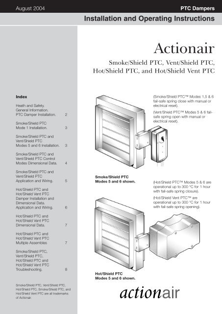
August 2004 PTC Dampers Installation and Operating Instructions Actionair Smoke/Shield PTC, Vent/Shield PTC, Hot/Shield PTC, and Hot/Shield Vent PTC Index Heath and Safety. General Information. PTC Damper Installation. 2 Smoke/Shield PTC Mode 1 Installation. 3 (Smoke/Shield PTC Modes 1,5 & 6 fail-safe spring close with manual or electrical reset). (Vent/Shield PTC Modes 5 & 6 failsafe spring open with manual or electrical reset). Smoke/Shield PTC and Vent/Shield PTC Modes 5 and 6 Installation. 3 Smoke/Shield PTC and Vent/Shield PTC Control Modes Dimensional Data. 4 Smoke/Shield PTC and Vent/Shield PTC Application and Wiring. 5 Hot/Shield PTC and Hot/Shield Vent PTC Damper Installation and Dimensional Data. Application and Wiring. 6 Hot/Shield PTC and Hot/Shield Vent PTC Dimensional Data. 7 Hot/Shield PTC and Hot/Shield Vent PTC Multiple Assembles 7 Smoke/Shield PTC, Vent/Shield PTC, Hot/Shield PTC and Hot/Shield Vent PTC Troubleshooting. 8 Smoke/Shield PTC, Vent/Shield PTC, Hot/Shield PTC, Smoke/Shield PTC, and Hot/Shield Vent PTC are all trademarks of Actionair. Smoke/Shield PTC Modes 5 and 6 shown. Hot/Shield PTC Modes 5 and 6 shown. (Hot/Shield PTC Modes 5 & 6 are operational up to 300 °C for 1 hour with fail-safe spring closure). (Hot/Shield Vent PTC are operational up to 300 °C for 1 hour with fail-safe spring opening).
- Page 2 and 3: PTC Dampers Health and Safety Gener
- Page 4 and 5: Smoke/Shield PTC Vent/Shield PTC Mo
- Page 6 and 7: Hot/Shield PTC Hot/Shield Vent PTC
- Page 8: PTC Dampers Troubleshooting Below i
August 20<strong>04</strong><br />
<strong>PTC</strong> <strong>Dampers</strong><br />
Installation and Operating Instructions<br />
<strong>Actionair</strong><br />
Smoke/Shield <strong>PTC</strong>, Vent/Shield <strong>PTC</strong>,<br />
Hot/Shield <strong>PTC</strong>, and Hot/Shield Vent <strong>PTC</strong><br />
Index<br />
Heath and Safety.<br />
General Information.<br />
<strong>PTC</strong> Damper Installation. 2<br />
Smoke/Shield <strong>PTC</strong><br />
Mode 1 Installation. 3<br />
(Smoke/Shield <strong>PTC</strong> Modes 1,5 & 6<br />
fail-safe spring close with manual or<br />
electrical reset).<br />
(Vent/Shield <strong>PTC</strong> Modes 5 & 6 failsafe<br />
spring open with manual or<br />
electrical reset).<br />
Smoke/Shield <strong>PTC</strong> and<br />
Vent/Shield <strong>PTC</strong><br />
Modes 5 and 6 Installation. 3<br />
Smoke/Shield <strong>PTC</strong> and<br />
Vent/Shield <strong>PTC</strong> Control<br />
Modes Dimensional Data. 4<br />
Smoke/Shield <strong>PTC</strong> and<br />
Vent/Shield <strong>PTC</strong><br />
Application and Wiring. 5<br />
Hot/Shield <strong>PTC</strong> and<br />
Hot/Shield Vent <strong>PTC</strong><br />
Damper Installation and<br />
Dimensional Data.<br />
Application and Wiring. 6<br />
Hot/Shield <strong>PTC</strong> and<br />
Hot/Shield Vent <strong>PTC</strong><br />
Dimensional Data. 7<br />
Hot/Shield <strong>PTC</strong> and<br />
Hot/Shield Vent <strong>PTC</strong><br />
Multiple Assembles 7<br />
Smoke/Shield <strong>PTC</strong>,<br />
Vent/Shield <strong>PTC</strong>,<br />
Hot/Shield <strong>PTC</strong> and<br />
Hot/Shield Vent <strong>PTC</strong><br />
Troubleshooting. 8<br />
Smoke/Shield <strong>PTC</strong>, Vent/Shield <strong>PTC</strong>,<br />
Hot/Shield <strong>PTC</strong>, Smoke/Shield <strong>PTC</strong>, and<br />
Hot/Shield Vent <strong>PTC</strong> are all trademarks<br />
of <strong>Actionair</strong>.<br />
Smoke/Shield <strong>PTC</strong><br />
Modes 5 and 6 shown.<br />
Hot/Shield <strong>PTC</strong><br />
Modes 5 and 6 shown.<br />
(Hot/Shield <strong>PTC</strong> Modes 5 & 6 are<br />
operational up to 300 °C for 1 hour<br />
with fail-safe spring closure).<br />
(Hot/Shield Vent <strong>PTC</strong> are<br />
operational up to 300 °C for 1 hour<br />
with fail-safe spring opening).
<strong>PTC</strong> <strong>Dampers</strong><br />
Health and<br />
Safety<br />
General Information<br />
All wiring should be carried out in<br />
accordance with the wiring details<br />
provided, the IEE and BS regulations,<br />
by a competent person.<br />
Care must be taken when installing<br />
and inspecting dampers, as they may<br />
close without warning due to a variety<br />
of reasons. Particularly this may be in<br />
the case of loss of electrical power, or<br />
fire signal to temperature rise in the<br />
ductwork. This is their prime function.<br />
Do not introduce any items, fingers or<br />
limbs between the blades.<br />
Prior to handling, check the weight of<br />
the unit and adopt suitable handling<br />
techniques.<br />
The <strong>PTC</strong> range of dampers are<br />
suitable for both horizontal and<br />
vertical applications, for airflow in<br />
either direction.<br />
<strong>PTC</strong> dampers to their maximum<br />
width and height dimensions can be<br />
used where the operating total<br />
system pressure is up to 1500 Pa<br />
and duct velocities to 15m/second.<br />
All Smoke/Fire dampers are life safety<br />
products and should be treated with<br />
care during handling, storage and<br />
installation.<br />
<strong>PTC</strong> dampers are designed for<br />
applications in normal dry filtered air<br />
systems and should be subject to a<br />
planned inspection programme,<br />
cleaning and light oil lubrication in<br />
accordance with good industry<br />
practice. When exposed to fresh air<br />
intakes and/or inclement conditions<br />
this may need to be performed more<br />
regularly based on experience gained<br />
from previous inspections.<br />
Specialist or aggressive environments<br />
may be unsuitable for this type of<br />
damper. This should have been<br />
checked with the Customer Service<br />
department at the time of order. If<br />
there are concerns this should be<br />
addressed before installation.<br />
For assistance with applications other<br />
than those described please contact<br />
our Customer Service Office.<br />
Please note all installations must be<br />
carried out in accordance with the<br />
approval of the relevant local<br />
authority.<br />
Damper Installation<br />
All installations must be made in<br />
accordance with approval of the<br />
relevant local authority and if<br />
HEVAC/HVCA frames have been<br />
supplied, also in accordance with<br />
HEVAC specification HVC 6/5/83,<br />
extracts of which are given below.<br />
Installation frames are delivered to<br />
site as a complete assembly with the<br />
appropriate <strong>PTC</strong> damper fitted<br />
therein.<br />
The damper shall be installed<br />
centrally in the thickness of a<br />
brickwork or concrete surrounding<br />
wall or floor, or in the case of thick<br />
walls or floors, so that the centre line<br />
of the frame is at least 50mm, but<br />
not more than 75mm, away from the<br />
nearest face of the wall or floor, in<br />
which the assembly is mounted.<br />
Care must be taken not to backfill<br />
past the line marked on the label<br />
on the shroud. If this does occur<br />
it will inhibit the fitting and<br />
removal of the interface.<br />
(See diagram on the right).<br />
The four tabs (building ties) forming<br />
each fixing point shall provide a<br />
positive fixing into the structure.<br />
In brickwork or blockwork walls the<br />
tabs shall be bent out and solidly<br />
built into the mortar joints between<br />
the brickwork or blockwork.<br />
In the cases of reinforced concrete<br />
walls or floors, the tabs shall be bent<br />
out and tied with wire to the<br />
reinforcing bars, which will be<br />
deliberately left protruding into the<br />
opening.<br />
The gap between the installation<br />
frame and builders work shall be<br />
backfilled with mortar or concrete on<br />
both sides of the flange.<br />
Adjacent frame assemblies must be<br />
separated by builder’s work of a<br />
minimum thickness of 225mm<br />
(between installation frame upstand<br />
flanges unless approval has been<br />
previously obtained from the<br />
appropriate Authority).<br />
In no case shall the HEVAC/HVCA<br />
frame and damper assembly be<br />
held in position merely by the<br />
adjacent ductwork, and it should be<br />
noted that in reinforced concrete<br />
structures (especially floors), it will<br />
not be sufficient to only backfill<br />
between the damper installation<br />
frame and surrounding opening<br />
with mortar or fine aggregate<br />
concrete mix without provision for<br />
tying in the frame to the<br />
surrounding reinforced concrete<br />
structure.<br />
When fitting the ductwork care<br />
must be taken to ensure that the<br />
ductwork is independently<br />
supported and not relying on the<br />
damper as a structural anchor, all<br />
in accordance with Ductwork<br />
Specification DW144. Access<br />
doors should also be fitted as<br />
required by DW144.<br />
For Hot/Shield <strong>PTC</strong> and<br />
Hot/Shield Vent <strong>PTC</strong> dampers<br />
fitted to thickened fire rated<br />
ductwork, please refer to notes<br />
on page 7.<br />
Backfill<br />
Limit Line<br />
on Label<br />
Damper Drive Shroud<br />
2
Smoke/Shield <strong>PTC</strong><br />
Control Mode Dimensional Data<br />
Mode 1 (Smoke/Shield only)<br />
Modes 5 and 6 Three position 180° (Pivotable Control Mode)<br />
130<br />
84 260<br />
28<br />
Mode 1 Installation Procedure<br />
248<br />
108<br />
130<br />
108<br />
70 25<br />
56<br />
12<br />
100<br />
112<br />
Smoke/Shield <strong>PTC</strong> Control Modes<br />
are located outside of the ductwork<br />
for ease of access and installation.<br />
Control Modes 5 and 6 can be fitted<br />
in any one of three orientations i.e.<br />
Vertically down (Position 1)<br />
Horizontally (Position 2), or<br />
Vertically up (Position 3).<br />
This can be simply and easily carried<br />
out on site, by repositioning the<br />
Location Plate and Control Mode on<br />
to the snaplock Drive Interface.<br />
This flexibility ensures that the<br />
damper and control mode require the<br />
minimal amount of room.<br />
108<br />
TOP<br />
315 ± 20mm<br />
5mm<br />
130mm<br />
135mm<br />
130mm<br />
40 ± *75mm<br />
*This dimension will vary on circular damper. Select<br />
dimension to give smoothest radius on bowden cable.<br />
1. Prepare ductwork<br />
Prepare ductwork for Mechanical<br />
fusible link as detailed below. (For<br />
ductless installations, a suitable sized<br />
plate or bracket must be fitted to the<br />
installation, to allow the fusible link<br />
fixing details to be achieved).<br />
●<br />
●<br />
●<br />
●<br />
●<br />
Within the Mode 1 kit of parts, is a<br />
self adhesive fusible link drilling<br />
template label.<br />
This template should be positioned<br />
on the duct in accordance with<br />
the dimensions shown above.<br />
Using a 3.0mm dia bit, drill 2 fixing<br />
holes.<br />
Using a 25mm dia hole cutter, drill<br />
the central hole.<br />
Remove sharp edges.<br />
2. Fit Control Mode<br />
●<br />
●<br />
●<br />
●<br />
Remove transit plate from damper<br />
shroud, and discard.<br />
Slide the interface and mode<br />
assembly into the shroud, having<br />
ensured that the slots in the<br />
interface case and the drive<br />
coupling are in line.<br />
Push the assembly fully home until<br />
the spring retaining pin engages<br />
through the location hole in the<br />
shroud (snaplock ).<br />
(The mode 1 option, unlike the<br />
mode 5/6, does not have the<br />
facility of alternative actuator fixing<br />
positions).<br />
3. Fit Mechanical Fusible Link<br />
●<br />
●<br />
Locate the fusible link assembly in<br />
the prepared hole in duct.<br />
Using the 2 self tapping screws<br />
provided, secure the assembly.<br />
4. Electrical Connections<br />
●<br />
Where use is to be made of the<br />
integral microswitch for indication<br />
purposes, this should be wired as<br />
described in the section<br />
‘Application and wiring’.<br />
5. Reset and Test Unit<br />
●<br />
If the mechanical fusible link is<br />
●<br />
●<br />
●<br />
●<br />
●<br />
not fitted to the ductwork, it will<br />
not be possible to reset the<br />
unit. – This is a safety feature.<br />
Using a 14mm A/F spanner, rotate<br />
the input shaft clockwise to reset<br />
the damper.<br />
NOTE: After resetting, never leave<br />
the spanner attached to the reset<br />
shaft.<br />
Test unit by simply unscrewing<br />
wing nut of the fusible link<br />
assembly. This will result in the<br />
damper releasing. Check for<br />
damper closure.<br />
Re-tighten the wing nut.<br />
FUSIBLE LINK<br />
Using a 14mm A/F spanner, rotate<br />
the input shaft clockwise to reset<br />
the damper.<br />
● Remove spanner.<br />
Note: It will not be possible to reset<br />
the control mode if the fusible link is<br />
not correctly installed.<br />
3
Smoke/Shield <strong>PTC</strong><br />
Vent/Shield <strong>PTC</strong><br />
Mode 5 and 6 Installation Procedure<br />
Smoke/Vent/<br />
Shield <strong>PTC</strong><br />
Damper<br />
Snaplock<br />
Retaining Pin<br />
Locating Hole<br />
Ductwork<br />
Transit Plate<br />
Electrical<br />
Thermal<br />
Release (ETR)<br />
Damper Drive<br />
Shroud<br />
Snaplock<br />
Drive Interface<br />
Control<br />
Mode 5/6<br />
Remove transit plate and discard.<br />
Slide the interface and mode<br />
assembly into the shroud, having<br />
ensured that the slots in the interface<br />
case and the drive coupling are in<br />
line.<br />
Push the assembly fully home until<br />
the sprung retaining pin engages<br />
through the location hole in the<br />
shroud (snaplock). If due to space<br />
restrictions, it is necessary to rotate<br />
the mode through 90° to alternative<br />
position see page 3, this may be<br />
achieved by doing the following:<br />
●<br />
●<br />
●<br />
●<br />
Remove the screw (8mm A/F)<br />
through the position indicator on<br />
the mode. Retain the screw and<br />
washer.<br />
Remove the mode and location<br />
plate.<br />
Taking care not to disturb the<br />
drive hexagon, replace the location<br />
plate in the new orientation.<br />
Replace the mode in the new<br />
orientation.<br />
● Replace the washer and screw<br />
tight.<br />
Select a suitable position for the<br />
Electrical Thermal Release (ETR) to<br />
be mounted through the ductwork.<br />
Ideally this should be in the top half<br />
of the duct and/or above the interface.<br />
Apply the self-adhesive template and<br />
drill the necessary holes.<br />
Push the ETR through the duct and<br />
ensure that both screws are used to<br />
hold it into position. Both screws<br />
should be tightened fully to ensure<br />
that both sections of the ETR are<br />
closed up together. This is a safety<br />
feature and should both sections not<br />
be closed the unit will not operate.<br />
If the ETR is not fitted to the<br />
ductwork, the unit will not<br />
operate.<br />
For ductless installations the ETR<br />
should be fitted onto the damper<br />
spigot (not casing) above the damper<br />
shroud, and in accordance with<br />
these fitting instructions.<br />
The damper should be manually<br />
reset and released, using the winder<br />
provided, to ensure that correct<br />
mechanical operation is achievable.<br />
It is possible to mechanically lock<br />
open the Smoke/Shield <strong>PTC</strong> damper<br />
to allow air to pass through it by<br />
using the winder provided. This may<br />
be necessary if electrical power is not<br />
available. However the ETR is not<br />
operable in this instance and the<br />
damper will not release automatically<br />
should the temperature rise or a fire<br />
occur.<br />
The unit must be wired as described<br />
in Section Application and Wiring<br />
details.<br />
When power is available the unit<br />
must be checked for correct<br />
electrical operation. Power on to<br />
reset, power off to release.<br />
The unit must also be checked by<br />
pushing, and holding, the test switch<br />
on the ETR to confirm that the<br />
damper releases. When pressure is<br />
removed from the switch the damper<br />
will reset. This may also be done<br />
after the initial installation test, to<br />
provide periodic operation of the<br />
damper to simulate actual fail-safe<br />
release under smoke/fire conditions.<br />
The cable connecting the mode and<br />
the ETR must not be shortened and<br />
care should be taken not to damage<br />
it. Shortening and/or damaging the<br />
cable will render the unit inoperable.<br />
This is due to a built in safety feature.<br />
Vent/Shield <strong>PTC</strong> dampers and<br />
associated control modes 5 and 6<br />
are reverse acting with spring action<br />
opening.<br />
4
Smoke/Shield<strong>PTC</strong><br />
Application and<br />
Wiring<br />
Smoke/Shield <strong>PTC</strong><br />
If integrating this unit with an Actionpac<br />
damper control system (LNS or EM)<br />
please refer to the relevant catalogue<br />
and specific project details.<br />
Vent/Shield <strong>PTC</strong><br />
Vent/Shield <strong>PTC</strong> dampers and<br />
associated control modes 5 and 6<br />
are reverse acting with spring action<br />
opening.<br />
Mode 1 (Manual System)<br />
Manual opening.<br />
Spring instant closure via mechanical<br />
fusible link.<br />
(Smoke/Shield version only, Vent/Shield not available.)<br />
GREEN/<br />
YELLOW<br />
BROWN<br />
BLUE<br />
BLACK<br />
E<br />
COMMON<br />
NORMALLY CLOSED<br />
NORMALLY OPEN<br />
VOLT FREE CONTACT<br />
CHANGES OVER WHEN<br />
DAMPER RESET<br />
RATED 240V 2A<br />
Mode 5 (24V System)<br />
Power On – Damper motors open.<br />
Power Off – Spring closure or via<br />
Electrical Thermal Release.<br />
External mechanical position indicator<br />
with pointer.<br />
Release Time ≈ 16 secs.<br />
Reset Time ≈ 140 secs.<br />
M<br />
1<br />
2<br />
S1<br />
S2<br />
S3<br />
N<br />
L<br />
SUPPLY<br />
24V A.C. OR D.C.<br />
TYPICALLY 7W (MOTORING) 2W (RESET)<br />
COMMON<br />
NORMALLY CLOSED<br />
NORMALLY OPEN<br />
VOLT FREE CONTACT<br />
CHANGES OVER WHEN<br />
DAMPER RELEASED<br />
RATED 24V 3A<br />
(Connect 24V via a safety isolating transformer.)<br />
S4<br />
COMMON<br />
S5<br />
S6<br />
NORMALLY CLOSED<br />
NORMALLY OPEN<br />
VOLT FREE CONTACT<br />
CHANGES OVER WHEN<br />
DAMPER RESET<br />
RATED 24V 3A<br />
TF 72 °C<br />
ELECTRICAL THERMAL RELEASE<br />
(SPRING BIASED TEST SWITCH)<br />
Mode 6 (230V System)<br />
Power On – Damper motors open.<br />
Power Off – Spring closure or via<br />
Electrical Thermal Release.<br />
External mechanical position indicator<br />
with pointer.<br />
Release Time ≈ 16 secs.<br />
Reset Time ≈ 1c secs.<br />
M<br />
1<br />
2<br />
S1<br />
S2<br />
S3<br />
N<br />
L<br />
SUPPLY<br />
220 - 240V A.C. 50/60Hz<br />
TYPICALLY 8W (MOTORING) 3W (RESET)<br />
COMMON<br />
NORMALLY CLOSED<br />
NORMALLY OPEN<br />
VOLT FREE CONTACT<br />
CHANGES OVER WHEN<br />
DAMPER RELEASED<br />
RATED 240V 3A<br />
(To isolate from main power supply, the system must<br />
incorporate a device which disconnects the phase<br />
conductors, with a least 3mm contact gap.)<br />
For non ETR applications refer to<br />
specific product label on Mode, prior<br />
to electrical connections.<br />
S4<br />
S5<br />
S6<br />
COMMON<br />
NORMALLY CLOSED<br />
NORMALLY OPEN<br />
VOLT FREE CONTACT<br />
CHANGES OVER WHEN<br />
DAMPER RESET<br />
RATED 240V 3A<br />
TF 72 °C<br />
ELECTRICAL THERMAL RELEASE<br />
(SPRING BIASED TEST SWITCH)<br />
General<br />
One metre of halogen free low smoke<br />
and fume electric cable is also<br />
included with each control mode for<br />
convenience of on site wiring. This<br />
also provides the distinct safety<br />
advantage of all electrics terminating<br />
outside the duct, eliminating potential<br />
in-duct fire hazards from wiring faults.<br />
The Electrical Thermal Release is prewired<br />
with 0.5m halogen free low<br />
smoke and fume cabling to Control<br />
Modes 5 and 6.<br />
A Manual test switch fitted on the<br />
ETR allows periodic operation of<br />
damper simulating actual fail-safe<br />
release under smoke/fire conditions.<br />
Smoke/Shield and Vent/Shield<br />
<strong>PTC</strong> <strong>Dampers</strong> and associated<br />
Control Modes 5 and 6 are<br />
available without the ETR where<br />
thermal operation is not required.<br />
5
Hot/Shield <strong>PTC</strong><br />
Hot/Shield Vent <strong>PTC</strong><br />
Damper Installation and Control<br />
Mode Fitting<br />
Dimensional Data<br />
161<br />
411<br />
Ductwork<br />
Hot/Shield,<br />
Hot/Shield Vent<br />
Damper<br />
Control Mode 5/6<br />
housed in thermally<br />
insulated enclosure<br />
191<br />
Transit<br />
Plate<br />
27<br />
421<br />
Damper<br />
Drive Shroud<br />
Snaplock<br />
Retaining Pin<br />
Series 2501<br />
Install the Hot/Shield <strong>PTC</strong> Damper<br />
(complete with factory fitted damper<br />
shroud and transit plate) into the<br />
structure, connect and fit ductwork to<br />
damper spigots. Remove transit plate<br />
and discard. Slide the snaplock<br />
drive interface into the damper drive<br />
shroud, snaplock into position.<br />
(See page 2.)<br />
(Care must be taken when back filling<br />
to ensure that the snaplock<br />
retaining pin location hole and the<br />
entry slot of the damper drive shroud<br />
is clear of builders work debris).<br />
The above dimensional data is for<br />
guide/general arrangement purposes.<br />
Please contact our Customer<br />
Service Office for details when<br />
incorporating thickened fire rated<br />
ductwork.<br />
Hot/Shield <strong>PTC</strong> Application and Wiring<br />
Hot/Shield Vent <strong>PTC</strong> <strong>Dampers</strong> and<br />
associated Control Modes are reverse<br />
action with spring operation<br />
Mode HM5 (24V System)<br />
Power On – Damper motors open.<br />
Power Off – Spring closure.<br />
Cable specification:<br />
Si HF Low Smoke and Fume,<br />
Halogen Free, to IEC 754-1.<br />
Conforming to 73/23/EEC directive.<br />
Release Time ≈ 16 secs.<br />
Reset Time ≈ 140 secs.<br />
(Connect 24V via a safety isolating transformer.)<br />
A.C./D.C.24V<br />
50 / 60 Hz<br />
10 V A<br />
7/2 W<br />
–30...+50 °C<br />
CONTINUOUS<br />
A.C.<br />
250V<br />
6(3)A<br />
M<br />
1<br />
2<br />
1<br />
2<br />
3<br />
4<br />
–<br />
+<br />
SUPPLY<br />
24V A.C. or D.C.<br />
VOLT FREE CONTACT<br />
CLOSED WHEN<br />
DAMPER RELEASED<br />
VOLT FREE CONTACT<br />
CLOSED WHEN<br />
DAMPER RESET<br />
Mode HM6 (230V System)<br />
Power On – Damper motors open.<br />
Power Off – Spring closure.<br />
Cable specification:<br />
Si HF Low Smoke and Fume,<br />
Halogen Free, to IEC 754-1.<br />
Conforming to 73/23/EEC directive.<br />
Release Time ≈ 16 secs.<br />
Reset Time ≈ 140 secs.<br />
(To isolate from main power supply, the system<br />
must incorporate a device which disconnects the<br />
phase conductors, with a least 3mm contact gap.)<br />
A.C. 230V<br />
50 / 60 Hz<br />
12.5 V A<br />
8 / 3 W<br />
–30...+50 °C<br />
CONTINUOUS<br />
A.C.<br />
250V<br />
6(3)A<br />
M<br />
BLUE<br />
BROWN<br />
1<br />
2<br />
3<br />
4<br />
N<br />
L1<br />
SUPPLY<br />
230V A.C 50/60 Hz<br />
VOLT FREE CONTACT<br />
CLOSED WHEN<br />
DAMPER RELEASED<br />
VOLT FREE CONTACT<br />
CLOSED WHEN<br />
DAMPER RESET<br />
6
Hot/Shield <strong>PTC</strong><br />
Hot/Shield Vent <strong>PTC</strong><br />
Dimensional Data<br />
Series 2501 and 3501 Basic Damper (square/rectangular)<br />
The following data is relevant to<br />
square/rectangular dampers Series 2501<br />
and 3501 when incorporating;<br />
STD Standard 1.2mm (approx) sheet<br />
steel ductwork.<br />
THK Thickened fire rated ductwork up to<br />
15mm thick.<br />
(For dimensional data outside of these<br />
parameters, refer to Customer Service<br />
Office).<br />
1. Transformation sections only required<br />
when duct widths and/or heights is less<br />
than 200mm, or if THK thickened fire<br />
rated ductwork is greater than 15mm.<br />
2. The following dampers with duct<br />
widths and/or heights as listed will be<br />
complete with transformation sections:<br />
Duct widths and/or heights between<br />
100mm – 175mm, will have nominal<br />
damper size of 200mm. Duct widths<br />
and/or heights between 176mm – 200mm,<br />
please refer to Customer Service Office.<br />
3. <strong>Dampers</strong> with duct widths and/or<br />
heights of between 200mm – 1000mm<br />
are supplied as nominal damper sizes and<br />
without transformation sections.<br />
4. Always refer to Customer Service<br />
Office for dimensional data when<br />
incorporation THK thickened fire<br />
rated ductwork, especially when<br />
thicker than 16mm.<br />
Series 2501<br />
Hot/Shield <strong>PTC</strong><br />
TRANSFORMATION<br />
SECTION<br />
Series 3501<br />
Hot/Shield Vent <strong>PTC</strong><br />
50<br />
25 DUCT WIDTH 25<br />
100 - 1000<br />
83<br />
90<br />
OVERALL WIDTH<br />
OF INSTALLATION<br />
FRAME IS DUCT<br />
WIDTH + 114MM<br />
SQUARE OR<br />
RECTANGULAR<br />
38 78 38 38<br />
SQUARE OR<br />
RECTANGULAR<br />
25 * DUCT HEIGHT<br />
100 - 1000<br />
* DUCT HEIGHT<br />
57<br />
DAMPER SPIGOTS 5MM<br />
UNDER DUCT SIZE<br />
Series 2601 and 3601 Basic Damper (circular)<br />
The following data is relevant to circular<br />
dampers Series 2601 and 3601 when<br />
incorporating;<br />
STD (Standard 1.2mm (approx) sheet<br />
steel ductwork).<br />
THK (Thickened fire rated ductwork up to<br />
35mm thick) (for dimensional data outside<br />
of these parameters, refer to Customer<br />
Service Office).<br />
5. Transformation sections are always<br />
included.<br />
6. <strong>Dampers</strong> with duct diameters between<br />
100mm diameter – 150mm diameter, will<br />
have nominal damper size of 200mm<br />
diameter. <strong>Dampers</strong> with duct diameters<br />
between 151mm diameter – 982mm<br />
diameter, will have nominal damper size<br />
+50mm. <strong>Dampers</strong> with a nominal damper<br />
size between 983mm diameter –<br />
1000mm diameter, please refer to<br />
Customer Service Office.<br />
7. Always refer to Customer Service<br />
Office for dimensional data when<br />
incorporation THK thickened fire<br />
rated ductwork, especially when<br />
thicker than 35mm.<br />
Series 2601<br />
Hot/Shield <strong>PTC</strong><br />
25<br />
Series 3601<br />
Hot/Shield<br />
Vent <strong>PTC</strong><br />
75<br />
50 DUCT DIAMETER 50<br />
100 - 1000<br />
108<br />
90<br />
OVERALL WIDTH<br />
OF INSTALLATION<br />
FRAME IS DUCT<br />
DIA + 164MM<br />
25 CIRCULAR<br />
65 38 78<br />
38 65<br />
CIRCULAR<br />
50 DUCT DIAMETER<br />
100 - 1000<br />
25<br />
25<br />
82<br />
DAMPER CIRCULAR<br />
SPIGOTS 3MM UNDER<br />
DUCT SIZE<br />
Multiple Assemblies<br />
Square and rectangular casings are<br />
available in multiple module<br />
arrangements, supplied complete<br />
with blanking strips for site assembly<br />
by others. Additional support as well<br />
as provision for thermal expansion<br />
(4mm/metre) should be allowed for<br />
on multiple assemblies.<br />
When fitted to fire rated<br />
ductwork, please refer to<br />
customer service office. Multiple<br />
assemblies require installation<br />
approval by the relevant local<br />
authority.<br />
7
<strong>PTC</strong> <strong>Dampers</strong><br />
Troubleshooting<br />
Below is a quick guide to problems that may be encountered. For detailed<br />
actions, reference to the main document is necessary.<br />
Please note modifications made to units will invalidate warranties etc.<br />
Product Commissioning<br />
and Maintenance<br />
Available.<br />
Interface Mode Assembly does<br />
not fit into the shroud on the<br />
damper.<br />
Key:–<br />
SSM1 Smoke/Shield Mode 1<br />
SSM5 Smoke/Shield Mode 5<br />
SSM6 Smoke/Shield Mode 6<br />
VSM5 Vent/Shield Mode 5<br />
VSM6 Vent/Shield Mode 6<br />
HSM5 Hot/Shield Mode 5<br />
HSM6 Hot/Shield Mode 6<br />
HSVM5 Hot/Shield Vent Mode 5<br />
HSVM6 Hot/Shield Vent Mode 6<br />
SSM1, SSM5, SSM6, HSM5 & HSM6<br />
•Check mode is in released position.<br />
VSM5, VSM6, HSVM5 & HSVM6<br />
•Check mode is in reset position.<br />
•Check damper drive shaft is in line<br />
to shroud, adjustment is made by<br />
manually setting blades to fully<br />
closed.<br />
•The slots on the non-access side<br />
of the shroud may be blocked (due<br />
to removal of transit plate prior to<br />
backfilling) - ensure adequate<br />
clearance.<br />
•Check alignment of drive coupling<br />
slot in interface. If out of line, the<br />
mode output drive is out of<br />
synchronisation with the interface<br />
drive. The mode will require to be<br />
removed, and the refitted correctly<br />
as follows:<br />
SSM5, SSM6, HSM5 & HSM6<br />
Remove mode. (Ensure released.)<br />
Align interface coupling with slot on<br />
interface. Refit mode with product<br />
label uppermost. (Including location<br />
plate and washer.)<br />
VSM5, VSM6, HSVM5, & HSVM6<br />
Remove mode. (Ensure reset.)<br />
Align interface coupling with slot on<br />
interface. Refit mode with product<br />
label uppermost.(Including location<br />
plate and washer.)<br />
Smoke/Shield Control Mode 1<br />
does not latch to reset position.<br />
Control Mode 1 difficult to<br />
install/remove from interface<br />
shroud.<br />
•Mechanical fusible link not fitted<br />
correctly to duct.<br />
•In released position, rotate the<br />
shaft fractionally with 14mm A/F<br />
spanner whilst installing/removing.<br />
The wing nut on the fusible link is<br />
not fully screwed clockwise to end<br />
travel.<br />
Control Mode (5 and 6) does<br />
not operate electrically.<br />
•The ETL is not correctly fitted to duct.<br />
•The mode is incorrectly wired.<br />
•The ETL cables have been<br />
damaged or tampered with.<br />
Control Mode operates, but<br />
limited, or no movement of<br />
damper blades is observed.<br />
•The mode is not correctly<br />
synchronised with the interface<br />
•The damper is damaged or poorly<br />
installed.<br />
•The retaining pin in the interface is<br />
not protruding through the location<br />
hole in the shroud.<br />
•Foreign matter is impeding blade<br />
movement.<br />
•Location plate omitted.<br />
•Mode not screwed down correctly.<br />
Interface assembly cannot be<br />
removed.<br />
•Mode is at incorrect position.<br />
SSM5, SSM6, HSM5, HSM6 -<br />
release position permits removal.<br />
VSM5, VSM6, HSVM5, HSVM6 -<br />
reset position permits removal.<br />
<strong>Actionair</strong>, South Street, Whitstable, Kent CT5 3DU England<br />
Tel: (01227) 276100 Fax: (01227) 264262 International Code: +441227<br />
Email: sales@actionair.co.uk Website: www.actionair.co.uk<br />
Part of Ruskin Air Management Limited<br />
•Interface coupling slot misaligned -<br />
try carefully manually adjusting<br />
blade slightly.<br />
NATIONAL<br />
ACCREDITATION<br />
OF CERTIFICATION<br />
BODIES<br />
Quality System Certificate No. 017 Assessed to<br />
BS 5760 Part 2/ISO 9002/EN 29002<br />
Produced by Graphic Partnership www.graphicpartnership.com<br />
LNNN00162 8/<strong>04</strong>


