Existing drywall partition (DWFX-F) - Actionair
Existing drywall partition (DWFX-F) - Actionair
Existing drywall partition (DWFX-F) - Actionair

Create successful ePaper yourself
Turn your PDF publications into a flip-book with our unique Google optimized e-Paper software.
<strong>Existing</strong> <strong>drywall</strong> <strong>partition</strong> (<strong>DWFX</strong>-F)<br />
Health and safety<br />
This process must be undertaken by competent persons. More than one person may be required to ensure the<br />
safe handling of large dampers and other materials.<br />
Use must be made of access equipment to ensure unsafe practices are not used to approach walls or difficult<br />
access areas.<br />
Standard site PPE should be used (minimum steel toe cap boots, hard hat); together with any protective<br />
eyewear, gloves and masks, when drilling or cutting is being undertaken. The latter should also be used when<br />
handing the wall construction materials, as defined by the material suppliers. If loud equipment is being used,<br />
hearing protection should be used.<br />
All waste materials should be collected and disposed of as defined by the relevant supplier.<br />
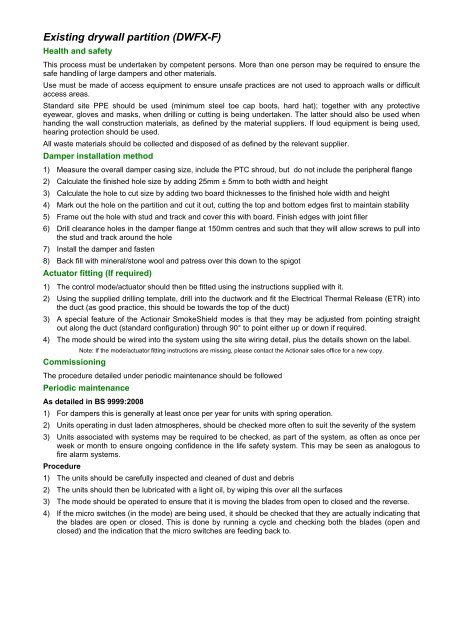
Damper installation method<br />
1) Measure the overall damper casing size, include the PTC shroud, but do not include the peripheral flange<br />
2) Calculate the finished hole size by adding 25mm ± 5mm to both width and height<br />
3) Calculate the hole to cut size by adding two board thicknesses to the finished hole width and height<br />
4) Mark out the hole on the <strong>partition</strong> and cut it out, cutting the top and bottom edges first to maintain stability<br />
5) Frame out the hole with stud and track and cover this with board. Finish edges with joint filler<br />
6) Drill clearance holes in the damper flange at 150mm centres and such that they will allow screws to pull into<br />
the stud and track around the hole<br />
7) Install the damper and fasten<br />
8) Back fill with mineral/stone wool and patress over this down to the spigot<br />
Actuator fitting (If required)<br />
1) The control mode/actuator should then be fitted using the instructions supplied with it.<br />
2) Using the supplied drilling template, drill into the ductwork and fit the Electrical Thermal Release (ETR) into<br />
the duct (as good practice, this should be towards the top of the duct)<br />
3) A special feature of the <strong>Actionair</strong> SmokeShield modes is that they may be adjusted from pointing straight<br />
out along the duct (standard configuration) through 90° to point either up or down if required.<br />
4) The mode should be wired into the system using the site wiring detail, plus the details shown on the label.<br />
Note: If the mode/actuator fitting instructions are missing, please contact the <strong>Actionair</strong> sales office for a new copy.<br />
Commissioning<br />
The procedure detailed under periodic maintenance should be followed<br />
Periodic maintenance<br />
As detailed in BS 9999:2008<br />
1) For dampers this is generally at least once per year for units with spring operation.<br />
2) Units operating in dust laden atmospheres, should be checked more often to suit the severity of the system<br />
3) Units associated with systems may be required to be checked, as part of the system, as often as once per<br />
week or month to ensure ongoing confidence in the life safety system. This may be seen as analogous to<br />
fire alarm systems.<br />
Procedure<br />
1) The units should be carefully inspected and cleaned of dust and debris<br />
2) The units should then be lubricated with a light oil, by wiping this over all the surfaces<br />
3) The mode should be operated to ensure that it is moving the blades from open to closed and the reverse.<br />
4) If the micro switches (in the mode) are being used, it should be checked that they are actually indicating that<br />
the blades are open or closed. This is done by running a cycle and checking both the blades (open and<br />
closed) and the indication that the micro switches are feeding back to.
AAF10704<br />
INSTALLATION DETAIL<br />
B<br />
A<br />
12.5 x 100mm (TYPE 5)<br />
PLASTERBOARD<br />
ALL ROUND, FIXED<br />
WITH DRYWALL<br />
SCREWS (@300 CTRS)<br />
INTO UDT72<br />
STUD CHANNELS<br />
12.5mm (TYPE 5)<br />
PLASTERBOARD<br />
ALL ROUND<br />
GAP PACKED WITH<br />
STONE MINERAL WOOL<br />
ALL ROUND<br />
60−100kg/m³<br />
DAMPER CASING<br />
VIEW A<br />
2−OFF 12.5mm (TYPE 5)<br />
PLASTERBOARD BOTH SIDES<br />
STONE WOOL<br />
60−100kg/m³<br />
UDT72 STUD CHANNEL<br />
50x50x3mm ANGLE CLEATS<br />
M10 DROP RODS<br />
<strong>DWFX</strong>−F FLANGE (TACK<br />
WELDED TO DAMPER CASING)<br />
FIXED WITH DRYWALL SCREWS<br />
(@ 150mm CTRS) INTO<br />
STUD CHANNEL, ALL ROUND.<br />
IF YOUR PROPOSED INSTALLATION<br />
DETAIL DIFFERS FROM THAT<br />
SHOWN, PLEASE DISCUSS THIS<br />
WITH THE BUILDING CONTROL<br />
AUTHORITY (BCA) USING THIS<br />
DOCUMENT AND THE ASSOCIATED<br />
FIRE TESTS, ASSESSMENTS AND<br />
OTHER DOCUMENTS SHOWN<br />
BELOW, SO THE BCA CAN DECIDE<br />
WHETHER YOUR PROPOSED<br />
METHOD DIFFERS SUFFICIENTLY<br />
FOR IT TO BE UNACCEPTABLE TO<br />
THEM (THE BCA)<br />
APPLICABLE TEST<br />
REPORT − BS EN1366−2<br />
BRE 256493<br />
ACTIONAIR REF: AA/F10704<br />
12.5<br />
12.5<br />
72<br />
120 MINUTES<br />
FIRE RESISTANCE<br />
INTEGRITY & LEAKAGE<br />
CONNECTING DUCTWORK OMITTED FOR CLARITY<br />
VIEW B<br />
(SIDE DETAIL)<br />
12.5mm ALL ROUND<br />
12.5<br />
12.50<br />
12.5<br />
www.actionair.co.uk<br />
VERTICAL APPLICATION<br />
SMOKE SHIELD <strong>DWFX</strong>−F<br />
DAMPER SIZE RANGE (mm):<br />
200 x 200 TO 1000 x 1000
AAF10705<br />
INSTALLATION DETAIL<br />
B<br />
A<br />
12.5 x 100mm (TYPE 5)<br />
PLASTERBOARD<br />
ALL ROUND, FIXED<br />
WITH DRYWALL<br />
SCREWS (@300 CTRS)<br />
INTO UDT52<br />
STUD CHANNELS<br />
12.5mm (TYPE 5)<br />
PLASTERBOARD<br />
ALL ROUND<br />
GAP PACKED WITH<br />
ROCKWOOL<br />
ALL ROUND<br />
60−100kg/m³<br />
DAMPER CASING<br />
VIEW A<br />
2−OFF 12.5mm (TYPE 5)<br />
PLASTERBOARD BOTH SIDES<br />
STONE WOOL 60−100kg/m³<br />
UDT52 STUD CHANNEL<br />
50x50x3mm ANGLE CLEATS<br />
<strong>DWFX</strong>−F FLANGE (TACK<br />
WELDED TO DAMPER CASING)<br />
FIXED WITH DRYWALL SCREWS<br />
(@ 150mm CTRS) INTO<br />
STUD CHANNEL, ALL ROUND.<br />
IF YOUR PROPOSED INSTALLATION<br />
DETAIL DIFFERS FROM THAT<br />
SHOWN, PLEASE DISCUSS THIS<br />
WITH THE BUILDING CONTROL<br />
AUTHORITY (BCA) USING THIS<br />
DOCUMENT AND THE ASSOCIATED<br />
FIRE TESTS, ASSESSMENTS AND<br />
OTHER DOCUMENTS SHOWN<br />
BELOW, SO THE BCA CAN DECIDE<br />
WHETHER YOUR PROPOSED<br />
METHOD DIFFERS SUFFICIENTLY<br />
FOR IT TO BE UNACCEPTABLE TO<br />
THEM (THE BCA)<br />
APPLICABLE TEST<br />
REPORT − BS EN1366−2<br />
BRE 259932<br />
ACTIONAIR REF: AA/F10705<br />
12.5<br />
12.5<br />
120 MINUTES<br />
FIRE RESISTANCE<br />
INTEGRITY<br />
72<br />
CONNECTING DUCTWORK OMITTED FOR CLARITY<br />
VIEW B<br />
(SIDE DETAIL)<br />
12.5mm ALL ROUND<br />
12.5<br />
12.5<br />
12.5<br />
www.actionair.co.uk<br />
VERTICAL APPLICATION<br />
FIRE SHIELD <strong>DWFX</strong>−F<br />
DAMPER SIZE RANGE (mm):<br />
100 x 100 TO 1250 x 1000