Proportional torque control automatic smoke and fire ... - Actionair
Proportional torque control automatic smoke and fire ... - Actionair
Proportional torque control automatic smoke and fire ... - Actionair

You also want an ePaper? Increase the reach of your titles
YUMPU automatically turns print PDFs into web optimized ePapers that Google loves.
December 2012<br />
SmokeShield PTC<br />
SmokeShield PTC TM<br />
<strong>Proportional</strong> Torque Control<br />
Automatic Smoke <strong>and</strong> Fire Dampers<br />
Features<br />
l <strong>Proportional</strong> Torque Control for<br />
optimised <strong>torque</strong> performance.<br />
l Unique snaplock drive<br />
interface ensures user friendly<br />
connection of Control Mode to<br />
Damper.<br />
l Tested <strong>and</strong> approved to<br />
BS ISO 10294-1:1996,<br />
BS EN 1366-2:1999 <strong>and</strong><br />
BS476 pt. 20:1987 Fire Test<br />
St<strong>and</strong>ards.<br />
l SmokeShield PTC is an LPCB<br />
approved product <strong>and</strong> conforms<br />
to the requirements of LPS1162<br />
issue 4.<br />
l Easy connection to square,<br />
rectangular, circular <strong>and</strong> flat oval<br />
ductwork.<br />
l Unique <strong>and</strong> patented Electrical<br />
Thermal Release for ultimate<br />
safety.<br />
l Halogen Free Low Smoke <strong>and</strong><br />
Fume cabling supplied as a<br />
st<strong>and</strong>ard safety feature.<br />
l Actionpac Damper Control<br />
System compatibility.<br />
l VentShield PTC reverse action<br />
dampers for <strong>smoke</strong> release or<br />
exhaust applications.<br />
l Pneumatic <strong>and</strong> Electrical ATEX<br />
actuator options available.<br />
l ASFP Grey Book Listed.<br />
Dampers Designed <strong>and</strong> Built in Britain<br />
Ruskin Air Management Limited<br />
www.ruskinuk.co.uk
SmokeShield PTC TM<br />
Introduction<br />
Specification<br />
SmokeShield PTC<br />
<strong>Proportional</strong> Torque Control Automatic<br />
Smoke <strong>and</strong> Fire Dampers with 75mm x<br />
0.5mm thick stainless steel aerodynamic<br />
interlocking blades incorporating synthetic<br />
seal, with steel blade end bearings <strong>and</strong><br />
peripheral gasketting. Housed in a<br />
galvanised steel fully welded 1.2mm<br />
spigotted casing suitable for square,<br />
rectangular, circular or flat oval<br />
connections.<br />
All PTC Dampers are supplied with<br />
blades in the closed position.<br />
The totally enclosed precise movement<br />
opposed blade drive shall be positioned<br />
out of airstream for protection against<br />
damage, be hard wearing <strong>and</strong> free<br />
running.<br />
The Control Mode/Damper connection<br />
shall be by means of the snaplock<br />
drive interface mechanism, which is<br />
totally independent of the ductwork.<br />
SmokeShield PTC Automatic Smoke<br />
<strong>and</strong> Fire Dampers with their<br />
appropriate <strong>control</strong> modes shall have<br />
spring Fail-Safe Closed operation.<br />
SmokeShield PTC Damper <strong>and</strong><br />
selected Control Mode (M1, M5, M6<br />
<strong>and</strong> M9 with ATEX options) as<br />
supplied by <strong>Actionair</strong>.<br />
<strong>Actionair</strong> has always been at the forefront<br />
in the innovative development, design <strong>and</strong><br />
manufacture of life safety dampers <strong>and</strong><br />
associated <strong>control</strong>s. Now with the unique<br />
SmokeShield PTC range of Automatic<br />
Smoke <strong>and</strong> Fire Dampers <strong>Actionair</strong><br />
continues this tradition.<br />
The Range<br />
The SmokeShield PTC range of Quality<br />
Engineered Dampers are suitable for air<br />
conditioning <strong>and</strong> ventilation systems<br />
requiring up to 4 hours protection. Refer<br />
to the <strong>Actionair</strong> Approved Fire <strong>and</strong><br />
Smoke Dampers Installation Manual for<br />
precise details.<br />
These aerodynamic stainless steel<br />
interlocking opposed blade dampers are<br />
fail-safe spring close with manual or<br />
electrical reset <strong>control</strong> modes.<br />
The VentShield PTC Damper range<br />
are reverse acting for <strong>smoke</strong> release<br />
or exhaust. (Manual system not<br />
available).<br />
SmokeShield PTC<br />
A Fire Rated Damper in accordance<br />
with British St<strong>and</strong>ard BS 9999: 2008<br />
(Ref 33.4.5.3). should be held in the<br />
Open Position by means of a<br />
Thermally Actuated Device set to<br />
operate at approximately 74 °C.<br />
SmokeShield PTC Automatic<br />
Smoke <strong>and</strong> Fire Control Dampers are<br />
Fire Rated Dampers as they are held<br />
in the Reset (Open) Position by a<br />
Thermally Actuated Device (Control<br />
Mode 1 – Mechanical Fusible Link,<br />
Control Modes 5 <strong>and</strong> 6 – Electrical<br />
Thermal Release, Control Mode 9 –<br />
Pneumatic Thermal Release) operating<br />
at a temperature of approximately<br />
72 °C ± 4 °C.<br />
Note: Thermally activated devices are<br />
not supplied with VentShield Control<br />
Modes as st<strong>and</strong>ard.<br />
VentShield PTC<br />
<strong>Proportional</strong> Torque Control Automatic<br />
Smoke Release Dampers with<br />
75mm x 0.5mm thick stainless steel<br />
aerodynamic blades incorporating<br />
synthetic seal, with steel blade end<br />
bearings <strong>and</strong> peripheral gasketting.<br />
Housed in a galvanised steel fully<br />
welded spigotted casing suitable for<br />
square, rectangular, circular or flat<br />
oval duct connections.<br />
The totally enclosed precise<br />
movement opposed blade drive shall<br />
be positioned out of airstream for<br />
protection against damage, be hard<br />
wearing <strong>and</strong> free running.<br />
The Control Mode/Damper<br />
connection shall be by means of the<br />
snaplock drive interface<br />
mechanism, which is totally<br />
independent of the ductwork.<br />
VentShield PTC Automatic Smoke<br />
Release Dampers with their<br />
appropriate <strong>control</strong> modes shall have<br />
spring Fail-Safe Open operation.<br />
VentShield PTC Damper <strong>and</strong><br />
selected Control Modes as supplied<br />
by <strong>Actionair</strong>.<br />
<strong>Proportional</strong><br />
Torque Control<br />
The <strong>control</strong> mode <strong>and</strong> snaplock drive<br />
interface provides the optimum<br />
mechanical advantage to the damper by<br />
delivering:<br />
the right <strong>torque</strong>, in the right place, at<br />
the right time.<br />
Application<br />
Parameters<br />
SmokeShield PTC <strong>and</strong> VentShield<br />
PTC Dampers to maximum width <strong>and</strong><br />
height dimensions (see pages 16 <strong>and</strong> 17)<br />
can be used where the operating total<br />
system pressure is up to 1500 Pascals<br />
<strong>and</strong> duct velocities to 15m/second.<br />
The SmokeShield PTC Damper blades<br />
are normally open <strong>and</strong> fail-safe to the<br />
closed position.This product is <strong>fire</strong> rated.<br />
The VentShield PTC Damper blades are<br />
normally closed <strong>and</strong> fail-safe to the open<br />
position for <strong>smoke</strong> release or exhaust.<br />
Dampers may be installed both vertically<br />
<strong>and</strong> horizontally. In addition, for vertical<br />
installations, the damper may be installed<br />
with the blades running vertically. Airflow<br />
can be from either direction.<br />
<strong>Actionair</strong> SmokeShield PTC <strong>and</strong><br />
VentShield PTC Dampers are designed<br />
for applications in normal dry filtered air<br />
systems. If exposed to fresh air intakes<br />
<strong>and</strong>/or inclement conditions, the dampers<br />
should be subject to a planned inspection<br />
programme.<br />
For specialist <strong>and</strong>/or aggressive applications,<br />
please refer to <strong>Actionair</strong> Sales Office.<br />
2 www.actionair.co.uk
SmokeShield PTC TM 3<br />
Casing Features<br />
With double skin spigotted galvanised<br />
steel (to BS EN 10346:2009) 1.2mm thick<br />
casing the SmokeShield PTC dampers<br />
comply to Class A <strong>and</strong> B of Eurovent<br />
Document 2/2 <strong>and</strong> Test Procedures for<br />
Classes A, B <strong>and</strong> C of HVCA Ductwork<br />
Specification DW144.<br />
Damper casings are manufactured with<br />
fully welded spigotted connections<br />
suitable for Square, Rectangular, Circular<br />
<strong>and</strong> Flat Oval duct connections.<br />
As an extra cost option, casings can be<br />
manufactured in 430 grade (Type 1.4016)<br />
Ferritic or 316 grade (Type 1.4401)<br />
Austenitic stainless steel, 1.2mm thick.<br />
Type SPG Square / Rectangular<br />
Type SPG Circular<br />
Type SPG Flat Oval<br />
Blade Features<br />
SmokeShield damper blades are<br />
aerodynamic double skin, Type 1.4016<br />
(430) Ferritic stainless steel, which are<br />
75mm x 0.5mm thick <strong>and</strong> interlock to<br />
form a positive <strong>smoke</strong> <strong>and</strong> <strong>fire</strong> resisting<br />
shield.<br />
Incorporated within the blade profile is a<br />
synthetic seal to ensure low closed blade<br />
<strong>smoke</strong> leakage.<br />
Stainless steel blade end bearing <strong>and</strong><br />
peripheral gasketting maintain the low<br />
closed blade <strong>smoke</strong> leakage whilst<br />
allowing for expansion under full <strong>fire</strong><br />
conditions.<br />
Optional Blade construction Type 1.4401<br />
(316) Austenitic stainless steel.<br />
12.7<br />
Multiple Assemblies<br />
Square <strong>and</strong> rectangular casings are<br />
available in multiple module arrangements<br />
supplied complete with joining channels<br />
for site fixing by others.<br />
LHD<br />
STD<br />
RHD<br />
PLAN VIEW<br />
STD<br />
RHD<br />
LHD<br />
SmokeShield PTC blade dimensions<br />
75 41.5<br />
STD<br />
RHD<br />
LHD<br />
STD<br />
RHD<br />
LHD<br />
SmokeShield PTC fail-safe closed<br />
VentShield PTC fail-safe open<br />
www.actionair.co.uk
SmokeShield PTC TM<br />
Damper – Control Mode Interface (Right H<strong>and</strong> Damper shown)<br />
snaplock Drive Interface<br />
Designed to develop<br />
<strong>Proportional</strong> Torque Control<br />
3 Position<br />
Location Plates<br />
Electrical (ATEX)<br />
Actuator<br />
SmokeShield PTC<br />
501 Damper<br />
Damper Drive Shroud <strong>and</strong><br />
Transit Plate<br />
Control Mode<br />
5/6 shown<br />
Mode 9, Pneumatic<br />
(ATEX) Actuator<br />
SmokeShield PTC Damper with<br />
unique snaplock Damper/Control<br />
Mode Interface<br />
Automatic Smoke <strong>and</strong> Fire Damper <strong>and</strong><br />
Control Mode assembly with a unique<br />
<strong>and</strong> dedicated <strong>Proportional</strong> Torque<br />
Control for optimised Damper/Control<br />
Mode <strong>torque</strong> performance.<br />
The unique snaplock drive interface<br />
ensures user friendly, easy <strong>and</strong> secure<br />
connection of the Control Mode to the<br />
Damper.<br />
The drive interface which is totally<br />
independent of the ductwork, eliminates<br />
the need for costly dedicated duct<br />
sections, <strong>and</strong> provides ease of<br />
connection to square, rectangular, circular<br />
<strong>and</strong> flat oval ductwork.<br />
This drive interface guarantees that only<br />
the correct <strong>and</strong> certified <strong>Actionair</strong><br />
products can be used.<br />
Control Options<br />
A choice of Control Modes are located<br />
outside of the ductwork for easy access<br />
<strong>and</strong> installation.<br />
All SmokeShield Control Modes must be in<br />
the released position prior to connection.<br />
Control Mode 1 Mechanical<br />
Manual reset – with volt free contact for<br />
provision of external indication of damper<br />
status.<br />
(Not available on Vent Shield).<br />
Control Modes 5 <strong>and</strong> 6 Electrical<br />
Optimised motor/spring return <strong>control</strong><br />
modes with remote reset-release facilities,<br />
with volt free contacts for provision of<br />
external indication, monitoring <strong>and</strong> <strong>control</strong><br />
by means of an Actionpac damper<br />
<strong>control</strong> system, or by a suitable<br />
alternative proprietary <strong>control</strong> format.<br />
The motorised Control Modes 5 <strong>and</strong> 6<br />
can be fitted in 3 positions through 180°<br />
(see page 15) allowing maximum on-site<br />
installation flexibility. (Position 2 is<br />
supplied as st<strong>and</strong>ard).<br />
Control Mode 9<br />
Pneumatic<br />
Note: VentShield PTC Dampers <strong>and</strong><br />
associated <strong>control</strong> modes are reverse<br />
action with spring opening (Mode 1 not<br />
available).<br />
4 www.actionair.co.uk
SmokeShield PTC TM<br />
Thermal Links <strong>and</strong> Release Types (SmokeShield Only)<br />
Mechanical Fusible Link<br />
Control Mode 1<br />
Fail-safe by means of a unique <strong>and</strong> patented Mechanical Fusible<br />
Link which operates at approx. 72 °C, complying with BS 9999 :<br />
2008 (Ref 33.4.5.3).<br />
The link assembly incorporates a safety feature that ensures the<br />
fail safe status of the damper if the link is not fitted on to the<br />
ductwork.<br />
A manual test may be performed by simple unscrewing the wing<br />
nut situated on the fusible link.<br />
Pneumatic Thermal Release (PTR)<br />
Control Mode 9<br />
Fail-safe is by means of a Pneumatic Thermal Release (PTR) which<br />
operates at 74°C, or if air supply is interrupted.<br />
FUSIBLE LINK<br />
Electrical Thermal Release (ETR)<br />
Control Modes 5 <strong>and</strong> 6<br />
Fail-safe by means of a unique <strong>and</strong> patented electrical thermal<br />
release which operates at approx 72 °C or if power supply is<br />
interrupted, complying with BS 9999 : 2008 (Ref 33.4.5.3).<br />
The ETR incorporates triple safety features, including an ingenious<br />
device that ensures the fail-safe status of the damper if the ETR is<br />
not fitted on to the ductwork.<br />
A manual test switch allows periodic operation of the damper for<br />
testing purposes simulating actual fail-safe release under<br />
<strong>smoke</strong>/<strong>fire</strong> conditions.<br />
For safety reasons the ETR/PTR is designed to operate once only<br />
when the activation temperature is reached.<br />
ETR Indication light<br />
As st<strong>and</strong>ard, a green LED lamp is built into the ETR<br />
housing. This gives the user a simple <strong>and</strong> clear visual<br />
check that the Actuator is receiving power, the ETR is<br />
correctly fitted, <strong>and</strong> the thermal fuse is intact.<br />
www.actionair.co.uk<br />
5
SmokeShield PTC TM<br />
Control Mode Details<br />
Control Mode 5 PTC <strong>and</strong> Control Mode 6 PTC<br />
Control Mode 9PTC<br />
Control Mode 5 PTC <strong>and</strong> Control Mode<br />
6 PTC 60 seconds MAX Reset/ 22<br />
seconds Release Operation.<br />
This series of <strong>control</strong> modes achieve 60<br />
seconds to drive to the end position, with<br />
a 22 second spring return time.<br />
As with all PTC modes, this series uses<br />
the snaplock interface. Fire rated<br />
dampers are primarily designed to be<br />
fitted into a wall or floor, <strong>and</strong> the interface<br />
displaces the mode from the line of the<br />
wall. Dampers may be installed <strong>and</strong> finally<br />
the mode removed from storage for easy<br />
fitting, thus preventing damage to the<br />
mode before it is required. End switches<br />
<strong>and</strong> LSF cable are provided as st<strong>and</strong>ard<br />
on these modes.<br />
Versions are available to allow fail-safe<br />
close for <strong>fire</strong> safety (SmokeShield) or failsafe<br />
open for <strong>smoke</strong> extract (VentShield).<br />
The Electro Thermal Release (ETR)<br />
supplied for <strong>fire</strong> damper use has an<br />
integral fail-safe device to ensure that it is<br />
installed into the ductwork correctly. ETR<br />
units are not supplied with VentShield,<br />
because these are designed to fail-safe<br />
open.<br />
End switches are provided with each<br />
mode, so that damper Reset <strong>and</strong> Release<br />
positions may be monitored. The mode is<br />
permanently attached to the mechanism<br />
driving the damper blades.<br />
Control Mode 9 PTC<br />
This mode has been developed to provide<br />
pneumatic operation of the damper <strong>and</strong> is<br />
available in spring return versions for failsafe<br />
operation. A Pneumatic Thermal<br />
Release assembly (PTR) is available<br />
(SmokeShield only) to react to <strong>fire</strong><br />
conditions. As with all PTC actuators, this<br />
series uses the snaplock interface. Switch<br />
box <strong>and</strong> solenoid accessories available.<br />
ATEX optional available when fitted with<br />
correct Solenoid Valve <strong>and</strong> Switch Box.<br />
M9 PTC Pneumatic Thermal Release /<br />
Air Off – Fail-safe Close<br />
M9 PTC Vent Pneumatic<br />
Air Off – Fail-safe Open<br />
SmokeShield <strong>and</strong> VentShield<br />
M5 PTC 10/2W (12.5VA MAX) 24V end switches SPDT 250V 6(3)A SmokeShield Thermal Release / Power Off – Fail-safe Close*<br />
M6 PTC 12/4W (14VA MAX) 230V end switches SPDT 250V 6(3)A SmokeShield Thermal Release / Power Off – Fail-safe Close*<br />
M5 PTC Vent 10/2W (12.5VA MAX) 24V end switches SPDT 250V 6(3)A VentShield Thermal Release / Power Off – Fail-safe Open*<br />
M6 PTC Vent 12/4W (14VA MAX) 230V end switches SPDT 250V 6(3)A VentShield Thermal Release / Power Off – Fail-safe Open*<br />
M5 PTC NON ETR 10/2W (12.5VA MAX) 24V end switches SPDT 250V 6(3)A SmokeShield Power Off – Fail-safe Close<br />
M6 PTC NON ETR 12/4W (14VA MAX) 230V end switches SPDT 250V 6(3)A SmokeShield Power Off – Fail-safe Close<br />
M5 PTC Vent NON ETR 10/2W (12.5VA MAX) 24V end switches SPDT 250V 6(3)A VentShield Power Off – Fail-safe Open<br />
M6 PTC Vent NON ETR 12/4W (14VA MAX) 230V end switches SPDT 250V 6(3)A VentShield Power Off – Fail-safe Open<br />
*SmokeShield Control Modes M5 PTC <strong>and</strong> M6 PTC are supplied as st<strong>and</strong>ard with the Electrical Thermal Release (ETR) (Not fitted<br />
to VentShield). The units Fail-safe by means of the unique <strong>and</strong> patented ETR device which operates at 72 °C, or if the power<br />
supply is off/interrupted. Complying with BS 9999 : 2008 (Ref 33.4.5.3). Non ETR versions Fail-safe when the power is<br />
off/interrupted.<br />
6 www.actionair.co.uk
SmokeShield PTC TM 7<br />
Control Mode Details Continued<br />
Control Mode 5 – 3P PTC<br />
Control Monitoring Station<br />
M5-3P 24V <strong>and</strong> M5-3P 230V<br />
CMS Control Stations<br />
M5 – 3P – CMS<br />
M5 – 3P – CMS (230V)<br />
Control Mode 5 – 3P PTC with additional<br />
facility for third (Control) Position.<br />
150 seconds Reset, 20 seconds<br />
Release.<br />
This 3 position <strong>control</strong> mode allows a<br />
damper to be moved to both the reset<br />
<strong>and</strong> release position, with the additional<br />
facility to move the damper to a third<br />
<strong>control</strong> position. The mode is given a<br />
2 - 10V DC signal, defining the <strong>control</strong><br />
position of the blades.<br />
A return signal of 2-10V DC is provided to<br />
allow monitoring of position.<br />
To support this actuator <strong>and</strong> allow<br />
positioning to be set local to the damper,<br />
<strong>Actionair</strong> have the M5-3P 24V <strong>and</strong> M5-<br />
3P 230V <strong>control</strong> units.<br />
SmokeShield <strong>and</strong> VentShield<br />
As with all PTC modes, this series uses<br />
the snaplock interface. Fire rated<br />
dampers are primarily designed to be<br />
fitted into a wall or floor, <strong>and</strong> the interface<br />
displaces the mode from the line of the<br />
wall. Dampers may be installed <strong>and</strong> then<br />
the mode removed from storage for easy<br />
fitting, thus preventing damage to the<br />
mode before it is required. End switches,<br />
LSF cable, <strong>and</strong> Electro Thermal Release<br />
(ETR) are provided as st<strong>and</strong>ard (not fitted<br />
on VentShield).<br />
Versions are available to allow fail-safe<br />
close for <strong>fire</strong> safety or fail-safe open for<br />
<strong>smoke</strong> venting.<br />
The M5-3P CMS (Control Monitoring<br />
Station) this <strong>control</strong> unit gives the user the<br />
opportunity to set a <strong>control</strong> position using<br />
an integral potentiometer, or use an<br />
externally supplied <strong>control</strong> voltage. It<br />
provides visual (lamp) <strong>and</strong> volt free (relay)<br />
indication of damper position (Released, at<br />
Control Position, Reset). A terminal is<br />
provided to allow feedback of the<br />
2-10V DC monitoring voltage. In addition, a<br />
<strong>fire</strong> alarm input may be made (NC) which<br />
will cause the damper to Release if the<br />
contact is broken. A second input is<br />
available to cause the damper to fully Reset<br />
to allow full air flow for <strong>smoke</strong> venting as an<br />
example. The <strong>fire</strong> alarm Release input takes<br />
precedence. Switches are provided that<br />
allow the unit to be driven to Release or<br />
Reset positions for testing purposes.<br />
M5-3P PTC 24V 7/2W (10VA) end switches SPDT 250V 6(3)A SmokeShield Thermal Release / Power Off – Fail-safe Close 2-10V Set Position<br />
M5-3P PTC NON ETR 24V 7/2W (10VA) end switches SPDT 250V 6(3)A SmokeShield Power Off – Fail-safe Close 2-10V Set Position<br />
M5-3P PTC Vent 24V 7/2W (10VA) end switches SPDT 250V 6(3)A VentShield Thermal Release / Power Off – Fail-safe Open 2-10V Set Position<br />
M5-3P PTC Vent NON ETR 24V 7/2W (10VA) end switches SPDT 250V 6(3)A VentShield Power Off – Fail-safe Open 2-10V Set Position<br />
SmokeShield Control Modes M5 –3P PTC are supplied with the Electrical Thermal Release (ETR) (Not fitted to VentShield).<br />
The units Fail-safe by means of the unique <strong>and</strong> patented ETR device which operates at 72 °C, or if the power supply is<br />
off/interrupted. Complying with BS 9999: 2008 (Ref 33.4.5.3) Non ETR versions Fail-safe when the power is off/interrupted.<br />
Control Mode 5 – 2P PTC <strong>and</strong> Control Mode 6 – 2P PTC<br />
Drive Open / Drive Closed. 60 seconds<br />
operation<br />
This 2 position <strong>control</strong> mode has been<br />
developed to provide drive open / drive<br />
closed damper operation. These modes do<br />
not have ETRs.<br />
As with all PTC actuators, this series uses<br />
the snaplock interface. All modes have<br />
LSF cables.<br />
SmokeShield <strong>and</strong> VentShield<br />
M5-2P PTC 24V 12W (18VA), end switches SPDT 250V 6(3)A<br />
M6-2P PTC 230V 8W (15VA), end switches SPDT 250V 6(3)A<br />
www.actionair.co.uk
SmokeShield PTC TM<br />
Application <strong>and</strong> Wiring - Smoke (with ETR)<br />
SmokeShield<br />
Mode 1 PTC (Manual System)<br />
Manual opening.<br />
Spring instant closure via mechanical<br />
fusible link.<br />
(SmokeShield version only, VentShield<br />
not available.)<br />
GREEN/<br />
YELLOW<br />
BROWN<br />
BLUE<br />
BLACK<br />
COMMON<br />
NORMALLY CLOSED<br />
NORMALLY OPEN<br />
DIAGRAM SHOWS ACTUATOR IN FULLY RELEASED STATE<br />
VOLT FREE CONTACT<br />
CLOSED WHEN<br />
DAMPER RESET<br />
(at 85 )<br />
RATED 250V 5A<br />
SmokeShield<br />
Mode 5 PTC (24V System)<br />
The following applies for ETR version.<br />
(ETR not supplied on VentShield.)<br />
Supply On – Damper motors reset.<br />
Supply Off – Spring release.<br />
Electrical Thermal Release.<br />
External mechanical position indicator with<br />
pointer.<br />
Release Time ≈ 22 secs.<br />
Reset Time ≈ 60 secs.<br />
(Connect 24V via a safety isolating<br />
transformer.)<br />
AC/DC 24V<br />
50 / 60 Hz<br />
12.5 VA<br />
10 / 2 W<br />
Imax<br />
8.3A @ 5ms<br />
AC<br />
250V<br />
6(3)A<br />
M<br />
BLACK<br />
WHITE<br />
1<br />
2<br />
1<br />
2<br />
3<br />
4<br />
5<br />
6<br />
–<br />
+<br />
SUPPLY<br />
24V AC or DC<br />
TYPICALLY 10W (MOTORING)<br />
2W (RESET)<br />
VOLT FREE<br />
CONTACT MADE BETWEEN<br />
1 AND 2 WHEN DAMPER<br />
FULLY RELEASED<br />
VOLT FREE<br />
CONTACT MADE BETWEEN<br />
4 AND 6 WHEN DAMPER<br />
FULLY RESET<br />
IP54 Rated.<br />
– 30...+50 C<br />
CONTINUOUS<br />
TF 72 C<br />
ELECTRICAL THERMAL RELEASE<br />
(MUST BE FITTED TO DUCTING<br />
FOR DAMPER OPERATION). NON<br />
ETR VERSION AVAILABLE ON<br />
REQUEST<br />
(SPRING BIASED TEST SWITCH)<br />
DIAGRAM SHOWS ACTUATOR IN FULLY RELEASED STATE<br />
SmokeShield<br />
Mode 6 PTC (230V System)<br />
The following applies for ETR version.<br />
(ETR not supplied on VentShield.)<br />
Supply On – Damper motors reset.<br />
Supply Off – Spring release.<br />
Electrical Thermal Release.<br />
External mechanical position indicator<br />
with pointer.<br />
Release Time ≈ 22 secs.<br />
Reset Time ≈ 60 secs.<br />
(To isolate from main power supply, the system<br />
must incorporate a device which disconnects<br />
the phase conductors, with a least 3mm<br />
contact gap.)<br />
Note: 120V A.C. version also available.<br />
IP54 Rated.<br />
AC 230V<br />
50 / 60 Hz<br />
14 VA<br />
12 / 4 W<br />
– 30...+50 C<br />
CONTINUOUS<br />
AC<br />
250V<br />
6(3)A<br />
M<br />
BLUE<br />
BROWN<br />
TF 72 C<br />
N<br />
L1<br />
1<br />
2<br />
3<br />
4<br />
5<br />
6<br />
SUPPLY<br />
230V AC 50/60 Hz<br />
TYPICALLY12W (MOTORING)<br />
4W (RESET<br />
VOLT FREE<br />
CONTACT MADE BETWEEN<br />
1 AND 2 WHEN DAMPER<br />
FULLY RELEASED<br />
VOLT FREE<br />
CONTACT MADE BETWEEN<br />
4 AND 6 WHEN DAMPER<br />
FULLY RESET<br />
ELECTRICAL THERMAL RELEASE<br />
(MUST BE FITTED FITTED TO<br />
DUCTING FOR DAMPER<br />
OPERATION). NON ETR VERSION<br />
AVAILABLE ON REQUEST<br />
(SPRING BIASED TEST SWITCH)<br />
DIAGRAM SHOWS ACTUATOR IN FULLY RELEASED STATE<br />
8 www.actionair.co.uk
SmokeShield PTC TM 9<br />
Application <strong>and</strong> Wiring -<br />
Vent (or Smoke Non-ETR)<br />
VentShield PTC Dampers <strong>and</strong><br />
associated Control Modes M5 <strong>and</strong> M6<br />
are reverse action with spring opening.<br />
VentShield Mode 5 (24V System)<br />
Supply On – Damper motors reset.<br />
Supply Off – Spring release.<br />
Cable specification:<br />
Si HF Low Smoke <strong>and</strong> Fume, Halogen<br />
Free, to IEC 754-1. Conforming to<br />
73/23/EEC directive.<br />
Release Time ≈ 22 secs.<br />
Reset Time ≈ 60 secs.<br />
(Connect 24V via a safety isolating<br />
transformer.)<br />
AC/DC 24V<br />
50 / 60 Hz<br />
12.5 VA<br />
10/2 W<br />
Imax<br />
8.3A @ 5ms<br />
– 30...+50 C<br />
CONTINUOUS<br />
AC<br />
250V<br />
6(3)A<br />
M<br />
BLACK<br />
WHITE<br />
1<br />
2<br />
1<br />
2<br />
3<br />
4<br />
–<br />
+<br />
SUPPLY<br />
24V AC or DC<br />
(Connect via a safety<br />
isolating transformer)<br />
VOLT FREE CONTACT<br />
CLOSED WHEN<br />
DAMPER RELEASED<br />
VOLT FREE CONTACT<br />
CLOSED WHEN<br />
DAMPER RESET<br />
IP54 Rated<br />
VentShield Mode 6 (230V System)<br />
Supply On – Damper motors reset.<br />
Supply Off – Spring release.<br />
Cable specification:<br />
Si HF Low Smoke <strong>and</strong> Fume, Halogen<br />
Free, to IEC 754-1. Conforming to<br />
73/23/EEC directive.<br />
Release Time ≈ 22 secs.<br />
Reset Time ≈ 60 secs.<br />
AC 230V<br />
50 / 60 Hz<br />
14 VA<br />
12 / 4 W<br />
M<br />
BLUE<br />
BROWN<br />
N<br />
L1<br />
1<br />
2<br />
SUPPLY<br />
230V AC 50/60 Hz<br />
VOLT FREE CONTACT<br />
CLOSED WHEN<br />
DAMPER RELEASED<br />
(To isolate from main power supply, the system must<br />
incorporate a device which disconnects the phase<br />
conductors, with a least 3mm contact gap.)<br />
Note: 120V A.C. version also available.<br />
– 30...+50 C<br />
CONTINUOUS<br />
AC<br />
250V<br />
6(3)A<br />
3<br />
4<br />
VOLT FREE CONTACT<br />
CLOSED WHEN<br />
DAMPER RESET<br />
IP54 Rated<br />
General (Electrical)<br />
One metre of halogen free low <strong>smoke</strong> <strong>and</strong><br />
fume electric cable is also included with<br />
Control Modes 1, 5 <strong>and</strong> 6 for<br />
convenience of on site wiring. This also<br />
provides the distinct safety advantage of<br />
all electrics terminating outside the duct,<br />
eliminating potential in-duct <strong>fire</strong> hazards<br />
from wiring faults.<br />
(Prewired Connection boxes available as<br />
factory fitted option.)<br />
The Electrical Thermal Release is prewired<br />
with 0.5m halogen free low <strong>smoke</strong><br />
<strong>and</strong> fume cable on Control Modes 5 <strong>and</strong><br />
6. (Not supplied on VentShield).<br />
A Manual test switch fitted on the ETR<br />
allows periodic operation of damper<br />
simulating actual fail-safe release under<br />
<strong>smoke</strong>/<strong>fire</strong> conditions.<br />
Control Modes 5 <strong>and</strong> 6 are available<br />
without the ETR where thermal operation<br />
is not required. (This would not comply<br />
with BS 9999: 2008).<br />
Smoke Shield or Vent Shield Mode 9<br />
PTC (Pneumatic Operation)<br />
Air On – Damper resets.<br />
Air Off – Spring release.<br />
Release time ≈ 2 – 4 secs.<br />
Reset time ≈ 2 – 4 secs.<br />
Air inlet – 6mm dia. quick fit coupling.<br />
74 °C Pneumatic Thermal Link (PTR).<br />
(PTR not supplied on VentShield.)<br />
Air pressure ≈ 5.5 – 8.0 bar.<br />
Air consumption to reset @ 5.5 bar –<br />
535CC.<br />
External mechanical position indicator.<br />
Test operation by removing fusible link<br />
element.<br />
www.actionair.co.uk
SmokeShield PTC TM<br />
Damper Installation <strong>and</strong> Control Mode Fitting<br />
Step 1<br />
Install the SmokeShield PTC Automatic Smoke <strong>and</strong> Fire<br />
Dampers (complete with transit plate) into the structure. Refer<br />
to the <strong>Actionair</strong> Approved Fire <strong>and</strong> Smoke Dampers Installation<br />
Manual.<br />
(Care must be taken when back filling to ensure that the<br />
snaplock retaining pin location hole <strong>and</strong> the entry slot of the<br />
damper drive shroud is clear of builders work debris).<br />
Right H<strong>and</strong><br />
Damper<br />
Shown<br />
Connect <strong>and</strong> fit duct work to damper spigots. Remove transit<br />
plate <strong>and</strong> discard (recycle).<br />
Transit Plate<br />
Step 2<br />
Slide the snaplock Drive Interface into the damper drive<br />
shroud, ‘snaplock’ into position.<br />
The ‘snaplock’ feature provides a user friendly, easy <strong>and</strong><br />
secure direct connection. It comes pre-set to enable direct fit to<br />
Smoke/VentShield damper.<br />
Control<br />
Mode 5/6<br />
shown<br />
Step 3 For Control Modes with Electrical Thermal<br />
Releases.<br />
Identify location for the Thermal Release. Ideally, this<br />
should be fitted to the top half of the duct, adjacent to<br />
the <strong>control</strong> mode. Fit the self adhesive drilling template<br />
(supplied) in this position. Drill holes as detailed on the<br />
template. Using the 2 fixing screws provided, secure<br />
the Electrical Thermal Release to the duct. Connect<br />
electrically, <strong>and</strong> test operation.<br />
As a safety feature the actuator will only operate if<br />
the ETR is correctly fitted to the duct.<br />
10 www.actionair.co.uk
SmokeShield PTC TM<br />
Damper Installation <strong>and</strong> Control Mode Fitting Continued<br />
Step 3 (Control Mode 1) SmokeShield only Step 3 (Control Mode 9)<br />
SMOKE/SHIELD<br />
DAMPER<br />
MECHANICAL<br />
FUSIBLE LINK<br />
SMOKE/SHIELD<br />
DAMPER<br />
FLOW<br />
RESTRICTOR<br />
AIR SUPPLY<br />
INLET<br />
315 ± 20mm<br />
TOP<br />
BOWDEN CABLE<br />
5mm<br />
108<br />
130mm<br />
40 ± *75mm<br />
130mm<br />
135mm<br />
*This dimension will vary on Circular<br />
Damper. Select dimension to give<br />
smoothest radius on bowden cable.<br />
Closed<br />
Open<br />
4mm NYLON<br />
TUBING<br />
500mm<br />
LENGTH<br />
PNEUMATIC<br />
THERMAL<br />
RELEASE<br />
Mark the Fusible Link position on the duct as dimensioned in the<br />
diagram above.<br />
Fit the self adhesive drilling template (supplied) in this position.<br />
Drill holes as detailed on template. Using the 2 fixing screws<br />
provided, secure the Fusible Link to the duct. Reset Damper<br />
using a 14mm A/F spanner, clockwise 1/4 turn. Test unit by<br />
simply unscrewing wing nut – Damper releases. For ductless<br />
installations a suitable sized plate or bracket must be fitted to the<br />
installation to allow the fitting of the Fusible Link.<br />
As a safety feature the Control Mode will only operate if the<br />
Fusible Link is correctly fitted to the duct.<br />
1. Select position for PTR. (SmokeShield only). Ideally this<br />
should be in the top half of the duct <strong>and</strong> sufficiently close to<br />
the actuator to allow easy connection of the 4mm diameter<br />
nylon tube supplied.<br />
2. Drill hole in selected position using a 30mm diameter hole<br />
cutter, removing any sharp edges.<br />
3. Position PTR <strong>and</strong> drill the 4 off 3mm diameter fixing holes.<br />
4. Remove PTR <strong>and</strong> apply approved <strong>fire</strong> retardant sealant on<br />
the duct around the hole.<br />
5. Refit PTR <strong>and</strong> secure with the 4 off Pozi head screws<br />
provided.<br />
6. Connect 4mm diameter tube to actuator <strong>and</strong> PTR.<br />
7. Connect 6mm diameter tube to input side of PTR.<br />
8. Connect air supply. Damper opens fully.<br />
9. Test operation.<br />
www.actionair.co.uk<br />
11
SmokeShield PTC TM<br />
Installation Methods, Classification <strong>and</strong> Test Report Summary<br />
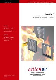
DWFX TM (DRY WALL FIX)<br />
Installation System<br />
Typically for installation into<br />
Dry Wall, Stud Partitions.<br />
DWFX-F Flange + Cleats<br />
Dry Wall<br />
DWFX-F Flange + Cleats<br />
Masonry Wall<br />
DWFX-C Dry Wall - Cleats<br />
HEVAC / HVCA Galvanised<br />
Steel Installation Frames<br />
Typically for installation into<br />
Blockwork, Concrete walls<br />
<strong>and</strong> floors.<br />
S&A Sleeve <strong>and</strong> Angle<br />
Installation System.<br />
Typically used to fill voids<br />
around dampers to complete<br />
a penetration seal.<br />
Classification<br />
E120, ES120<br />
Classification<br />
E120, ES120<br />
Classification<br />
E120, ES120<br />
BSEN 1366-2 Test /<br />
Assessment<br />
BRE 256493<br />
BSEN 1366-2 Test /<br />
Assessment<br />
BRECC 270714A<br />
BSEN 1366-2 Test /<br />
Assessment<br />
BRE 231741<br />
S&A Sleeve <strong>and</strong> Angle +<br />
BATT + Dry Wall<br />
S&A Sleeve <strong>and</strong> Angle +<br />
BATT + Masonry Wall<br />
S&A Sleeve <strong>and</strong> Angle Dry<br />
Wall<br />
S&A Sleeve <strong>and</strong> Angle<br />
Masonry Wall<br />
Classification<br />
E120, ES120<br />
Classification<br />
E120, ES120<br />
Classification<br />
E120, ES120<br />
Classification<br />
E120, ES120<br />
BSEN 1366-2 Test /<br />
Assessment<br />
BRE 267924<br />
BSEN 1366-2 Test /<br />
Assessment<br />
BRECC 270714A<br />
BSEN 1366-2 Test /<br />
Assessment<br />
BRECC 270714A<br />
BSEN 1366-2 Test /<br />
Assessment<br />
BRECC 270714C<br />
12 www.actionair.co.uk
SmokeShield PTC TM 13<br />
HEVAC / HVCA Installation<br />
Frame Vertical<br />
HEVAC / HVCA Installation<br />
Frame Horizontal<br />
S & A Sleeve <strong>and</strong> Angle<br />
+ BATT Horizontal<br />
Classification<br />
E240, ES120<br />
BSEN 1366-2 Test /<br />
Assessment<br />
BRE 259933<br />
Classification<br />
E240, ES240<br />
BSEN 1366-2 Test /<br />
Assessment<br />
BRE 231740<br />
Classification<br />
E120, ES90<br />
BSEN 1366-2 Test /<br />
Assessment<br />
BRE 275926<br />
Approved Installations<br />
The <strong>Actionair</strong> Approved Fire <strong>and</strong> Smoke<br />
Dampers Installation manual is available<br />
for free download, along with DW 145<br />
check sheets, on our web site.<br />
Building <strong>and</strong> Local Authority <strong>control</strong>,<br />
cannot refuse these tested methods.<br />
www.actionair.co.uk
SmokeShield PTC TM<br />
Accessories<br />
Electrical<br />
Damper Test Unit<br />
Reset <strong>and</strong> release indication.<br />
Spring bias (power OFF) test switch.<br />
Power normally ON.<br />
Damper Status Indicator<br />
Reset <strong>and</strong> release indication.<br />
DTU24<br />
DTU120<br />
DTU230<br />
DSI24<br />
DSI120<br />
DSI230<br />
A range of indicator panels, push button switches <strong>and</strong><br />
damper test units are also available. The housing for<br />
these units are manufactured in rigid ABS plastic.<br />
The Damper Connection Box is in galvanised steel.<br />
24V AC/DC<br />
120V AC<br />
230V AC<br />
24V AC/DC<br />
120V AC<br />
230V AC<br />
Damper Control Unit<br />
Switch ON/OFF function.<br />
Reset <strong>and</strong> release indication.<br />
DCU24<br />
DCU120<br />
DCU230<br />
24V AC/DC<br />
120V AC<br />
230V AC<br />
Damper Release <strong>and</strong> Indication<br />
Module (DRIM)<br />
This is designed for <strong>control</strong> <strong>and</strong><br />
monitoring of the electrically operated<br />
Smoke Shield PTC Fire <strong>and</strong> Smoke<br />
dampers.<br />
It will operate from 24V, 120V or 230V<br />
supplies, 50 or 60 Hz.<br />
Selection of the operating voltage is<br />
by use of internal links on the PCB,<br />
prior to installation <strong>and</strong> connection<br />
of actuator <strong>and</strong> supply.<br />
The DRIM may be used singly to<br />
provide local damper <strong>control</strong>, or<br />
in pairs to provide <strong>control</strong> from<br />
either side of a damper. It can<br />
also operate 2 actuators when<br />
dampers are provided in 2<br />
multiple sections.<br />
LED position <strong>and</strong> operation<br />
indication is provided.<br />
Operation is by push button to<br />
close <strong>and</strong> twist to re-open<br />
damper.<br />
Tested to BS EN 61010 -1: 2001<br />
<strong>and</strong> is CE compliant.<br />
IP44 rated.<br />
Operating range 5 - 40 °C.<br />
M5 <strong>and</strong> M6 – 2P Damper Control Unit<br />
Switch power open/power close. Open<br />
<strong>and</strong> closed indication.<br />
DRIM<br />
M52PDCU<br />
M62PDCU<br />
24V – 230V AC/DC<br />
24V AC/DC<br />
230V AC<br />
Damper Connection Box<br />
(All Voltages).<br />
DCB<br />
24V – 230V AC/DC<br />
M5 – 3P – CMS Control Unit<br />
M53PCMS<br />
24V AC/DC<br />
230V M5 – 3P – CMS Control Unit<br />
230V M53PCMS<br />
230V AC<br />
Pneumatic<br />
Solenoid, (24V, 120V, or 230V). EEXD Solenoid, (24V,<br />
120V, or 230V). Damper Status Beacon. Switchbox <strong>and</strong><br />
Status Beacon. Zone 2 Switchbox <strong>and</strong> Status Beacon.<br />
24 – 230V AC/DC<br />
14 www.actionair.co.uk
Control Mode Dimensions <strong>and</strong> Orientation<br />
Mode 1 (SmokeShield only)<br />
5<br />
130<br />
SmokeShield PTC Control Modes are located<br />
outside of the ductwork for ease of access <strong>and</strong><br />
installation.<br />
INPUT<br />
SHAFT<br />
108<br />
14<br />
130<br />
70 25<br />
Snaplock<br />
RETAINING PIN<br />
LOCATION HOLE<br />
Modes 5 <strong>and</strong> 6 Three position 180° (Pivotable<br />
Control Mode)<br />
SmokeShield PTC Control Modes are located<br />
outside of the ductwork for ease of access <strong>and</strong><br />
installation.<br />
Control Modes 5 <strong>and</strong> 6 can be fitted in any one of<br />
three orientations i.e.<br />
Vertically down (Position 1)<br />
Horizontally (Position 2), or<br />
Vertically up (Position 3).<br />
This can be simply <strong>and</strong> easily carried out on site,<br />
by repositioning the Location Plate (see page 4)<br />
<strong>and</strong> Control Mode on to the snaplock Drive<br />
Interface.<br />
This flexibility ensures that the damper <strong>and</strong> <strong>control</strong><br />
mode require the minimal amount of room.<br />
(Supplied in position 2 as st<strong>and</strong>ard.)<br />
25<br />
84 260<br />
28<br />
56<br />
109<br />
108<br />
12<br />
100<br />
112<br />
Position 3<br />
Position 2<br />
Position 1<br />
248<br />
Mode 9 Pneumatic Control<br />
143<br />
SmokeShield PTC Control Modes are located<br />
outside of the ductwork for ease of access <strong>and</strong><br />
installation.<br />
SmokeShield PTC TM 15<br />
108<br />
222<br />
155<br />
Hytock - 71 (ATEX)<br />
Aluminium Switch Box<br />
Hytock - 71 (ATEX)<br />
Polycarbonate Switch Box<br />
HYTORK 115<br />
HYTORK + SWITCHBOX 235<br />
HYTORK 115<br />
HYTORK + SWITCHBOX 205<br />
HYTORK 222<br />
WIDTH 110<br />
HYTORK 222<br />
WIDTH 110<br />
www.actionair.co.uk
SmokeShield PTC TM<br />
Dimensional Data<br />
For Rectangular Dampers spigots are 5mm under duct size.<br />
* Widths <strong>and</strong> heights available in 1mm increments.<br />
Base Dampers<br />
Please refer to the <strong>Actionair</strong> Approved Fire <strong>and</strong> Smoke Dampers<br />
Installation Manual.<br />
Dampers with Installation Systems<br />
Dampers with DWFX-F<br />
HEVAC / HVCA IF<br />
Dampers with S&A<br />
Rectangular Dampers Series 501 <strong>and</strong> 1501<br />
For Ducts with widths of 100 – 150mm*<br />
For Ducts with heights<br />
of 100 – 150mm*<br />
OVERALL FLANGE<br />
WIDTH IS 398mm<br />
OVERALL FLANGE<br />
HEIGHT IS 395mm<br />
OVERALL WIDTH OF<br />
INSTALLATION<br />
FRAME IS 314mm<br />
OVERALL HEIGHT OF<br />
INSTALLATION<br />
FRAME IS 340mm<br />
OVERALL FLANGE WIDTH<br />
IS 398mm<br />
OVERALL FLANGE HEIGHT<br />
IS 395mm<br />
25 = 100 - 150 =<br />
DUCT WIDTH<br />
25<br />
50<br />
90<br />
50<br />
50<br />
25<br />
50<br />
25<br />
50<br />
DUCT HEIGHT<br />
25<br />
25 = 151 - 199 = 25<br />
25 200 -1000<br />
25<br />
200 - 1000<br />
200<br />
DUCT WIDTH<br />
250<br />
For Ducts with widths <strong>and</strong> heights of 200 – 1000mm*<br />
DUCT WIDTH<br />
28<br />
For Ducts with widths of 151 – 199mm*<br />
28<br />
28<br />
DUCT HEIGHT DUCT HEIGHT DUCT HEIGHT<br />
200 - 1000<br />
151 - 199<br />
100 - 150<br />
38 38 78<br />
38 38 78<br />
38 38<br />
For Ducts with heights<br />
of 151 – 199mm*<br />
38 78<br />
38 38<br />
38<br />
200 - 1000 250<br />
200<br />
60 60<br />
60<br />
60<br />
OVERALL FLANGE<br />
WIDTH IS 448mm<br />
OVERALL FLANGE<br />
HEIGHT IS 445mm<br />
50<br />
200<br />
250<br />
OVERALL FLANGE WIDTH<br />
DUCT WIDTH + 198mm<br />
OVERALL FLANGE HEIGHT<br />
DUCT HEIGHT + 195mm<br />
60<br />
60<br />
50<br />
200 - 1000<br />
83<br />
200<br />
57<br />
OVERALL WIDTH OF<br />
INSTALLATION<br />
FRAME IS 364mm<br />
OVERALL HEIGHT OF<br />
INSTALLATION<br />
FRAME IS 390mm<br />
83<br />
57 250<br />
90<br />
OVERALL WIDTH OF<br />
INSTALLATION FRAME<br />
DUCT WIDTH + 114mm<br />
OVERALL HEIGHT OF<br />
INSTALLATION FRAME<br />
DUCT HEIGHT + 140mm<br />
83<br />
57 200 - 1000<br />
90<br />
60<br />
60<br />
200<br />
OVERALL FLANGE WIDTH<br />
IS 448mm<br />
OVERALL FLANGE HEIGHT<br />
IS 445mm<br />
60<br />
60<br />
50<br />
250<br />
OVERALL FLANGE WIDTH<br />
DUCT WIDTH + 198mm<br />
OVERALL FLANGE HEIGHT<br />
+ DUCT HEIGHT + 195mm<br />
60 60<br />
50<br />
200 - 1000<br />
16 www.actionair.co.uk
Base Dampers<br />
Dampers with Installation Systems<br />
Dampers with DWFX-F HEVAC / HVCA IF<br />
Dampers with S&A<br />
Circular Dampers Series 601 <strong>and</strong> 1601<br />
1mm Increments *<br />
=<br />
DUCT DIA.<br />
100 - 150*<br />
=<br />
50<br />
OVERALL FLANGE WIDTH IS 398<br />
OVERALL FLANGE HEIGHT IS 395mm<br />
60<br />
50<br />
OVERALL WIDTH OF INSTALLATION<br />
FRAME IS 314mm<br />
OVERALL HEIGHT OF INSTALLATION<br />
FRAME IS 340mm<br />
90<br />
OVERALL FLANGE WIDTH =<br />
448mm<br />
OVERALL FLANGE HEIGHT =<br />
445mm<br />
50<br />
60<br />
DUCT DIA.<br />
100 - 150*<br />
=<br />
83<br />
28<br />
200<br />
CIRCULAR<br />
CIRCULAR<br />
=<br />
25<br />
25<br />
25<br />
60<br />
57<br />
=<br />
DUCT DIA.<br />
=<br />
151 - 199*<br />
OVERALL FLANGE WIDTH =<br />
DUCT DIA + 248mm<br />
OVERALL FLANGE HEIGHT =<br />
DUCT DIA + 245mm<br />
OVERALL WIDTH OF INSTALLATION FRAME<br />
= DUCT DIA + 166mm<br />
OVERALL HEIGHT OF INSTALLATION FRAME<br />
= DUCT DIA + 190mm<br />
50 DUCT DIA.<br />
1mm Increments *<br />
50 DUCT WIDTH * 50<br />
300 – 950*<br />
75<br />
25<br />
108<br />
=<br />
200<br />
=<br />
65 38 78<br />
38<br />
65<br />
60<br />
1mm Increments *<br />
DUCT DIA.<br />
151 - 199*<br />
= =<br />
OVERALL FLANGE WIDTH IS 448mm OVERALL WIDTH OF INSTALLATION<br />
OVERALL FLANGE HEIGHT IS 445mm FRAME IS 364mm<br />
OVERALL HEIGHT OF INSTALLATION<br />
FRAME IS 390mm<br />
50<br />
90<br />
OVERALL FLANGE WIDTH =<br />
448mm<br />
OVERALL FLANGE HEIGHT =<br />
445mm<br />
50<br />
50<br />
60<br />
60<br />
25 250<br />
28<br />
25<br />
25 250<br />
=<br />
= CIRCULAR<br />
65 38 78<br />
38<br />
65<br />
CIRCULAR<br />
60<br />
83<br />
57<br />
60<br />
1mm Increments *<br />
DUCT DIA.<br />
50 200 - 950* 50<br />
OVERALL FLANGE WIDTH =<br />
DUCT DIA T 248mm<br />
OVERALL FLANGE HEIGHT =<br />
DUCT DIA + 245mm<br />
50<br />
75<br />
50<br />
60<br />
50<br />
60<br />
200 - 950*<br />
25<br />
DUCT DIA. + 50<br />
28<br />
25<br />
DUCT DIA. + 50<br />
(FOR DUCT DIA 951 - 1000mm<br />
DUCT DIA + 30mm)<br />
25<br />
25<br />
25 CIRCULAR<br />
CIRCULAR<br />
60<br />
108<br />
82<br />
60<br />
(FOR DUCT DIA 951 - 1000mm<br />
DUCT DIA + 30mm)<br />
65 38 78<br />
38<br />
65<br />
50<br />
90<br />
Flat Oval Dampers Series 701 <strong>and</strong> 1701<br />
OVERALL FLANGE WIDTH<br />
DUCT WIDTH + 248mm<br />
OVERAL FLANGE HEIGHT<br />
DUCT HEIGHT + 245mm<br />
60<br />
50<br />
OVERALL WIDTH OF INSTALLATION FRAME<br />
DUCT WIDTH +166mm<br />
OVERALL HEIGHT OF INSTALLATION FRAME<br />
DUCT HEIGHT +190mm<br />
90<br />
OVERALL FLANGE WIDTH =<br />
DUCT DIA T 248mm<br />
OVERALL FLANGE HEIGHT =<br />
DUCT DIA + 245mm<br />
60<br />
50<br />
SmokeShield PTC TM 17<br />
For Circular <strong>and</strong> Flat Oval Dampers spigots are 3mm under<br />
duct size. *Diameters <strong>and</strong> flat oval diameters in 1mm<br />
increments.<br />
For Installation Details Please refer to the <strong>Actionair</strong> Approved<br />
Fire <strong>and</strong> Smoke Damper Installation Manual.<br />
50 DUCT HEIGHT<br />
200 - 500*<br />
DUCT WIDTH. + 50mm*<br />
(FOR DUCT WIDTH 951 - 1000mm<br />
25 DUCT WIDTH + 30mm) 25<br />
28<br />
DUCT HEIGHT +50<br />
25<br />
25 FLAT OVAL<br />
65 38 78<br />
38 65<br />
FLAT OVAL<br />
60<br />
82<br />
60<br />
www.actionair.co.uk
SmokeShield PTC TM<br />
DWFX-C Dimensional Data<br />
50 50 50<br />
14<br />
24<br />
Acoustic Data<br />
The data presented is from the<br />
Laboratory Determination of Acoustic <strong>and</strong><br />
Aerodynamic Performance of<br />
SmokeShield PTC Automatic Smoke <strong>and</strong><br />
Fire Control Dampers.<br />
A programme of extensive tests was<br />
carried out in the Reverberation Chamber<br />
<strong>and</strong> North Transmission Chamber of<br />
Sound research Laboratories Limited,<br />
Holbrook Hall, Sudbury, Suffolk, generally<br />
in accordance with BRITISH STANDARDS<br />
Nos. 4196, 4773, 4856, 4857 <strong>and</strong> 4954.<br />
This independent test facility is approved<br />
under the NAMAS Scheme.<br />
From the selection of a duct velocity<br />
within the operational parameters of the<br />
damper a resultant pressure drop from<br />
Graph 1 can be determined <strong>and</strong> the sum<br />
of these two components applied to the<br />
Velocity x Pressure Drop Vs Sound Power<br />
Level Graph. (Graph 2)<br />
The graph is the result of a full<br />
range of acoustic tests on SmokeShield<br />
PTC Automatic Smoke <strong>and</strong> Fire Control<br />
Dampers with the blades set in their fully<br />
open position.<br />
The Spectrum Correction Data is applied<br />
to the number obtained from the graph<br />
<strong>and</strong> a complete Sound Spectrum of Flow<br />
Generated Noise for both Outlet (in duct)<br />
<strong>and</strong> Breakout (casing radiated) can be<br />
obtained from Table 1.<br />
Pressure Drop Vs Velocity<br />
Graph 1<br />
PRESSURE DROP (Pa)<br />
100<br />
90<br />
80<br />
70<br />
60<br />
50<br />
40<br />
30<br />
20<br />
10<br />
9<br />
8<br />
7<br />
6<br />
5<br />
4<br />
3<br />
2<br />
EXAMPLE LINE<br />
Example:<br />
Duct with a design velocity of 8 m/sec.<br />
SmokeShield PTC Damper Series 501<br />
fully open.<br />
Pressure Drop = 21 Pa (Graph 1).<br />
Multiply Velocity x Pressure Drop<br />
8 x 21 = 168.<br />
1<br />
1 2 3 4 5 6 7 8 9 10 15<br />
TYPE 501<br />
VELOCITY (m/s)<br />
TYPE 601<br />
From Sound Power Graph (Graph 2) plot<br />
168 on horizontal Velocity/Pressure axis<br />
against 501 outlet (induct) graph to obtain<br />
47 dBW on Vertical Sound Power Level<br />
Axis. Add or subtract corrections to the<br />
47 dBW to provide full spectrum analysis<br />
using appropriate Correction Table.<br />
18 www.actionair.co.uk
Velocity (m/s) X Pressure Drop (Pa) Vs<br />
Sound Power Level (dBW)<br />
90<br />
80<br />
1500<br />
SOUND POWER LEVEL (dBW)<br />
70<br />
60<br />
50<br />
40<br />
30<br />
20<br />
10<br />
0<br />
10<br />
SmokeShield PTC TM 19<br />
Graph 2<br />
Damper Leakage<br />
Graph 3<br />
SmokeShield PTC <strong>and</strong> VentShield<br />
PTC closed blade leakage as tested on<br />
a damper 1000mm wide x 1000mm high.<br />
Leakage data at Ambient temperature (Cold Smoke).<br />
EXAMPLE LINE<br />
20<br />
30<br />
40<br />
50<br />
60<br />
70<br />
80<br />
90<br />
100<br />
501 BREAKOUT<br />
601 BREAKOUT<br />
200<br />
300<br />
601 OUTLET (INDUCT)<br />
400<br />
500<br />
600<br />
700<br />
800<br />
900<br />
1000<br />
501 OUTLET (INDUCT)<br />
2000<br />
3000<br />
4000<br />
5000<br />
6000<br />
7000<br />
8000<br />
9000<br />
10000<br />
PRESSURE DIFFERENTIAL ACROSS CLOSED DAMPER (Pa)<br />
1200<br />
1000<br />
500<br />
300<br />
250<br />
200<br />
150<br />
120<br />
100<br />
VELOCITY X PRESSURE DROP (m/s Pa)<br />
70<br />
Correction Tables<br />
Table 1<br />
SmokeShield PTC Outlet (Induct) Spectrum Corrections<br />
Octave B<strong>and</strong> Hz 63 125 250 500 1k 2k 4k 8k<br />
Series 501 dB 5 4 5 5 3 1 -3 -5<br />
Series 601 dB 9 4 4 5 3 1 -3 -6<br />
Table 2<br />
SmokeShield PTC Breakout Spectrum Corrections<br />
Octave B<strong>and</strong> Hz 63 125 250 500 1k 2k 4k 8k<br />
Series 501 dB 8 11 9 6 -3 -6 -14 -17<br />
Series 601 dB 6 10 8 4 -3 -3 -11 -14<br />
50<br />
5 10 20 30 40 50 100<br />
LEAKAGE (I/s)<br />
The SmokeShield PTC Damper has<br />
been tested in accordance with BS ISO<br />
10294-1 <strong>and</strong> BS EN 1366-2. It achieved<br />
ES classification in accordance with BS<br />
ISO 10294-2:1999. ES classification allows<br />
a maximum of 200m 3 / Hr/m 2 (corrected to<br />
20 °C) hot gas leakage throughout the test<br />
at 300 Pa pressure differential across the<br />
damper.<br />
www.actionair.co.uk
SmokeShield PTC TM<br />
Actionpac Damper Control Systems<br />
Electro Mechanical Systems<br />
Actionpac EMS - St<strong>and</strong>ard Control <strong>and</strong><br />
Monitoring System<br />
Control <strong>and</strong> monitoring of Mode 5 or<br />
Mode 6 damper actuators in groups of<br />
12, 24 or 36.<br />
Actionpac EMB - Bespoke Control <strong>and</strong><br />
Monitoring System Control Panel<br />
The EMB Control Panels typically consists<br />
of the appropriate number of switches to<br />
provide individual or group <strong>control</strong>, LED<br />
indication for status monitoring <strong>and</strong> all<br />
necessary relays <strong>and</strong> timers to comply<br />
with the customer needs for fully or semi<br />
<strong>automatic</strong> damper operation. The EMB<br />
panels are purposely manufactured for<br />
any particular project to suit specific client<br />
requirements.<br />
Addressable Systems<br />
Actionpac LNS Smart Cost Effective<br />
Intelligent Damper Control <strong>and</strong><br />
Monitoring System<br />
Actionpac Smart for the<br />
<strong>control</strong>/monitoring of up to 36 off<br />
SmokeShield dampers.<br />
Actionpac 60/120 (LNS 60/120)<br />
Intelligent Damper Control <strong>and</strong><br />
Monitoring System<br />
Actionpac LNS 60 for the<br />
<strong>control</strong>/monitoring of up to 60 off<br />
SmokeShield dampers.<br />
Actionpac LNS 120 for the<br />
<strong>control</strong>/monitoring of up to 120 off<br />
SmokeShield dampers.<br />
Actionpac LNS3 Intelligent Damper<br />
Control <strong>and</strong> Monitoring System<br />
The Actionpac LNS3 system represents a<br />
new generation of <strong>smoke</strong>/<strong>fire</strong> damper<br />
<strong>control</strong>. The system has been designed<br />
with the user in mind, providing an<br />
advanced tool that simplifies installation<br />
<strong>and</strong> commissioning of <strong>smoke</strong>/<strong>fire</strong><br />
dampers <strong>and</strong> peripheral devices. The<br />
Panel PC operates on a Windows<br />
platform making it universally accepted<br />
<strong>and</strong> utilises solid state technology for<br />
optimum reliability.<br />
It’s server architecture delivers new<br />
benefits such as reduced commissioning<br />
time, simplified operation <strong>and</strong> scope for<br />
future growth.<br />
The Actionpac LNS3 system is designed<br />
to protect life <strong>and</strong> property from damage<br />
caused by <strong>smoke</strong> <strong>and</strong> <strong>fire</strong>, by providing<br />
the means to:–<br />
• Compartmentalise <strong>fire</strong> zones.<br />
• Reduce the spread of <strong>smoke</strong> <strong>and</strong> <strong>fire</strong>.<br />
• Keep escape routes <strong>and</strong> <strong>fire</strong>-fighting<br />
access open.<br />
• Allow pressurisation <strong>and</strong> <strong>smoke</strong> extract<br />
by combined operation of dampers<br />
<strong>and</strong> fans.<br />
Benefits<br />
• <strong>Actionair</strong> experience <strong>and</strong> know-how in<br />
the damper market<br />
• <strong>Actionair</strong> Smoke/Fire Dampers LPCB<br />
approved<br />
• Allows for phased commissioning <strong>and</strong><br />
future expansion<br />
• Backward compatible<br />
• CE marked, EMC <strong>and</strong> LVD compliant<br />
• Customer testimonials available<br />
• Hundreds of prestigious reference sites<br />
• Powerful <strong>and</strong> very flexible functionality<br />
accommodates any last minute<br />
changes to strategy, zones, damper<br />
quantities, references <strong>and</strong> descriptions<br />
etc <strong>and</strong> enables st<strong>and</strong>ardisation of<br />
software (no bespoke site specific<br />
versions required)<br />
• Off site system witnessing can be<br />
arranged<br />
• Open <strong>and</strong> interoperable protocol<br />
(LonWorks ® ) allows possible support<br />
by others <strong>and</strong> future proof lifecycle<br />
preventative maintenance costs<br />
• Optional networking of panels to a<br />
central <strong>control</strong> <strong>and</strong> monitoring panel -<br />
up to 32 networked panels to meet<br />
practically any building’s damper<br />
requirements<br />
• Optional <strong>automatic</strong> scheduled damper<br />
testing, including omit option for critical<br />
dampers<br />
• Optional remote access via internet<br />
• System designed to cater for<br />
environmental occupancy (energy<br />
saving) as well as the building’s<br />
<strong>smoke</strong>/<strong>fire</strong> strategy<br />
Actionpac LNS3 Intelligent Damper<br />
Control <strong>and</strong> Monitoring System<br />
Fully comprehensive<br />
brochures are available on<br />
all Actionpac products.<br />
Visit the <strong>Actionair</strong> website<br />
w.w.w.actionair.co.uk <strong>and</strong><br />
download the relevant pdf.<br />
20 www.actionair.co.uk
Typical Network Schematic<br />
General Schematic of Actionpac LNS3 Damper Control System<br />
To additional<br />
devices as required<br />
To additional<br />
devices as required<br />
SFDI<br />
Smoke Fire Damper Interface<br />
One per Control Mode<br />
24/230 volt<br />
(local power<br />
by others)<br />
3PSFDI<br />
CSS Smoke ES Rated<br />
Fire Damper<br />
Smoke Shaft Ventilation<br />
System Series SSV<br />
SDI<br />
24/230 volt<br />
(local power<br />
by others)<br />
Damper Control Mode*<br />
24/230 volt<br />
(local power<br />
by others)<br />
SFDI<br />
NDI404<br />
3PSFDI<br />
Network Digital Input / Output<br />
Interface - provides up to four<br />
inputs / outputs<br />
3 Position Smoke/Fire<br />
Damper Interface<br />
one per Control Mode<br />
SFDI<br />
24/230 volt<br />
(local power<br />
by others)<br />
SDI<br />
Smoke damper Interface<br />
one per Control Mode<br />
24/230 volt<br />
(local power<br />
by others)<br />
SDI<br />
One SFDI, SDI or 3PFSDI is required<br />
per Damper/Section.<br />
Supply to each Damper Interface from<br />
nearest local distribution board.<br />
SFDI<br />
Outputs<br />
24/230 volt<br />
(local power<br />
by others)<br />
SFDI<br />
24/230 volt<br />
(local power<br />
by others)<br />
NDI404<br />
24/230 volt<br />
(local power<br />
by others)<br />
Inputs<br />
Panel Router(s)<br />
Vent Panel<br />
B.M.S.<br />
OUTPUTS<br />
INPUTS<br />
SmokeShield PTC TM 21<br />
Fire Alarm Inputs<br />
BMS Inputs<br />
Fireman’s Switch Inputs<br />
Panel PC to Panel PC<br />
Cable (Cat 5e)<br />
To additional<br />
Panel PCs<br />
as required<br />
www.actionair.co.uk
SmokeShield PTC TM<br />
Customer Service<br />
Approvals<br />
<strong>Actionair</strong> provides quality products<br />
backed by a dedicated team committed<br />
to providing the very best in customer<br />
service.<br />
Offering experienced technical backup,<br />
comprehensive sales <strong>and</strong> administrative<br />
customer support, product<br />
commissioning <strong>and</strong> maintenance service.<br />
Maintenance<br />
The SmokeShield PTC Dampers<br />
are designed for applications in<br />
normal dry filtered air systems <strong>and</strong><br />
should be subjected to a planned<br />
inspection programme, with cleaning<br />
<strong>and</strong> light oil lubrication in<br />
accordance with BS9999. When<br />
exposed to fresh air intakes <strong>and</strong>/or<br />
inclement conditions this may need<br />
to be performed more regularly<br />
based on experience gained from<br />
previous inspections.<br />
Approved by LPCB for use in up to 4<br />
hour constructions.<br />
Refer to the <strong>Actionair</strong> Approved Fire <strong>and</strong><br />
Smoke Dampers Installation Manual.<br />
The SmokeShield PTC Damper tested<br />
<strong>and</strong> assessed to<br />
BS ISO 10294-1,<br />
BS EN 1366-2 <strong>and</strong><br />
BS 476 pt. 20. It achieved ES<br />
classification in accordance with<br />
BS ISO 10294-2:1999.<br />
Low gas/<strong>smoke</strong> <strong>and</strong> <strong>fire</strong> integrity to<br />
Classification ES in vertical <strong>and</strong> horizontal<br />
test installations.<br />
An LPCB approved product, compliant to<br />
the new Loss Prevention Council Design<br />
Guide for Fire Protection of Buildings.<br />
Fire tested in vertical <strong>and</strong> horizontal<br />
applications under dynamic conditions by<br />
The Loss Prevention Council.<br />
Corrosion tested to BS EN 60068-2-52:<br />
1996 to satisfy the requirements within<br />
LPS 1162.<br />
Complies with the latest DW 144 casing<br />
leakage specification.<br />
The Electrical Control Modes satisfy<br />
requirements of the following st<strong>and</strong>ard(s)<br />
or other normative documents, EN 6100-<br />
6-2 / EN 6100-6-3 / EN60730-1 / EN<br />
60730-2-14 following the provision of<br />
Directive 2004/108/EG, 2006/95/EG.<br />
Seismic Qualification<br />
SS501PTC, have been subjected to<br />
triaxial seismic qualification tests in<br />
accordance with BNFL Technical Services<br />
Report ET 372 Schedule No. Twelve, to<br />
the levels detailed in Costain Document<br />
6733-0250-064-10-0020, Rev C,<br />
Specification for Diesel Generator <strong>and</strong><br />
Load Bank. The testing was also in<br />
general accordance with IEEE 344-2004<br />
IEEE Recommended Practice for Seismic<br />
Qualification of Class 1E Equipment for<br />
Nuclear Power Generating Stations –<br />
Time History Method.<br />
Quality Assurance<br />
Approximate Weights (Kg)<br />
Square or Circular 100 150 200 250 300 350 400 450 500 550 600 650 700 750 800 850 900 950 1000<br />
Duct Size (mm)<br />
Series 501 Square 3.4 3.4 3.4 4.2 4.8 5.6 6.5 7.4 8.6 9.6 10.8 12.4 13.6 14.9 16.2 17.7 19.2 20.8 23.5<br />
Series 501 Square + I/F 6.2 6.2 6.2 7.4 8.7 10.3 11.9 13.2 14.6 16.3 18.5 20.5 22.1 24.0 25.9 28.1 30.3 32.4 34.5<br />
Series 601 Circular 5.3 5.3 5.3 6.1 7.2 8.4 9.6 11.2 12.6 14.0 15.9 17.5 19.1 20.7 22.5 24.3 26.2 29.3 32.1<br />
Series 601 Circular + I/F 8.5 8.5 8.5 10.0 11.9 13.7 15.4 17.1 19.2 21.8 24.0 26.0 28.2 30.4 32.8 35.3 37.8 40.3 43.1<br />
Control Mode 1 (SmokeShield only) (including drive interface) 4.1Kg<br />
Control Modes 5, 5 - 3P, 5 - 2P, 6, 6 - 2P <strong>and</strong> 9 (including drive interface) 4.4Kg<br />
The information contained herein is subject to change<br />
without notice due to continuing research <strong>and</strong><br />
development.<br />
22 www.actionair.co.uk
SmokeShield PTC TM<br />
Ordering Information<br />
Example<br />
Quantity Series Fixing Options Duct Size Control Mode Accessories<br />
3 SS501/PTC IF 600(W) x 450(H) M5<br />
Number of<br />
units required<br />
SS501/PTC<br />
SmokeShield PTC<br />
Square or Rectangular<br />
(Fail-safe closed)<br />
SS601/PTC<br />
SmokeShield PTC<br />
Circular<br />
(Fail-safe closed)<br />
SS701/PTC<br />
SmokeShield PTC<br />
Flat Oval<br />
(Fail-safe closed)<br />
VS1501/PTC<br />
VentShield PTC<br />
Square or Rectangular<br />
(Fail-safe open)<br />
VS 1601/PTC<br />
VentShield PTC<br />
Circular<br />
(Fail-safe open)<br />
VS1701/PTC<br />
VentShield PTC<br />
Flat Oval<br />
(Fail-safe open)<br />
1. DWFX-F<br />
Dry Wall Fixing System<br />
Flange plus Cleats<br />
2. DWFX-C<br />
Dry Wall Fixing System<br />
Cleats<br />
3. IF HEVAC / HVCA<br />
Installation Frame<br />
4. Sleeve <strong>and</strong> Angle<br />
5. Other Special<br />
Fixings<br />
M1 PTC<br />
Manual System<br />
M5 PTC<br />
24V 10W (12.5VA)<br />
M6 PTC<br />
230V 12W (14VA)<br />
M5 PTC Vent NON ETR<br />
24V 10W (12.5VA)<br />
M6 PTC Vent NON ETR<br />
230V 12W (14VA)<br />
M5 PTC NON ETR<br />
24V 10W (12.5VA)<br />
M6 PTC NON ETR<br />
230V 12W (14VA)<br />
M5 PTC Vent<br />
24V 10W (12.5VA)<br />
M6 PTC Vent<br />
230V 12W (14VA)<br />
M5-2P ON/OFF<br />
24V 7W (10VA)<br />
M6-2P ON/OFF<br />
230V 8W (12.5VA)<br />
M5-3P PTC<br />
24V 7W (10VA)<br />
M5-3P PTC Vent NON ETR<br />
24V 7W (10VA)<br />
M5-3P PTC NON ETR<br />
24V 7W (10VA)<br />
M5-3P PTC Vent<br />
24V 7W (10VA)<br />
M9 PTC<br />
Pneumatic Operation<br />
ATEX<br />
Electrical<br />
1. DTU<br />
Damper Test Unit<br />
Damper Test Unit For Control<br />
Modes. Spring bias test<br />
switch providing illuminated<br />
reset <strong>and</strong> release status<br />
2. DSI<br />
Damper Status Indicator<br />
Reset <strong>and</strong> Release Indication<br />
3. DCU<br />
Damper Control Unit<br />
Damper Control Unit for<br />
Control Modes. Switch<br />
ON/OFF function, reset <strong>and</strong><br />
release indication<br />
4. DRIM<br />
Damper Release <strong>and</strong><br />
Indication Module<br />
5. M52PDCU / M62PDCU<br />
Switch Power Open/Power<br />
Close. Open <strong>and</strong> Closed<br />
Indication<br />
6. DCB<br />
Connection Box<br />
For Control Modes 1, 5 <strong>and</strong> 6<br />
(see page 14 for above)<br />
7. M5 – 3P - CMS<br />
Control Unit<br />
8. 230V M5 – 3P - CMS<br />
Control Unit<br />
Pneumatic<br />
24 Volt Solenoid, (24, 120, or<br />
230 Volt).<br />
Status Beacon, Switchbox<br />
<strong>and</strong> Status Beacon.<br />
PTR XNNN05017<br />
Mechanical<br />
snaplock Interface Locking<br />
Plate (See page 10)<br />
M9 PTC Vent NON PTR<br />
Pneumatic Operation<br />
ATEX<br />
Actionpac Damper<br />
Control Systems<br />
(See page 20 <strong>and</strong> 21)<br />
SCHISCHEK Electrical<br />
ATEX<br />
www.actionair.co.uk<br />
23
SmokeShield PTC<br />
Ruskin Air Management Limited<br />
is a ISO 9001 <strong>and</strong> 14001 registered<br />
company.<br />
The statements made in this brochure or by our<br />
representatives in consequence of any enquiries<br />
arising out of this document are given for information<br />
purposes only. They are not intended to have any<br />
legal effect <strong>and</strong> the company is not to be regarded<br />
as bound thereby. The company will only accept<br />
obligations which are expressly negotiated for <strong>and</strong><br />
agreed <strong>and</strong> incorporated into a written agreement<br />
made with its customers.<br />
Due to a policy of continuous product development<br />
the specification <strong>and</strong> details contained herein are<br />
subject to alteration without prior notice.<br />
Comprehensive <strong>and</strong> detailed information<br />
is available for all <strong>Actionair</strong> products.<br />
Visit our website at www.actionair.co.uk<br />
Ruskin Air Management Limited<br />
South Street, Whitstable, Kent<br />
CT5 3DU Engl<strong>and</strong>.<br />
Tel: 01227 276100<br />
Fax: 01227 264262<br />
Email: sales@actionair.co.uk<br />
Website: www.actionair.co.uk<br />
LNNN00112