Hot Shield PTC High Operating Temperature Smoke ... - Actionair
Hot Shield PTC High Operating Temperature Smoke ... - Actionair
Hot Shield PTC High Operating Temperature Smoke ... - Actionair

Create successful ePaper yourself
Turn your PDF publications into a flip-book with our unique Google optimized e-Paper software.
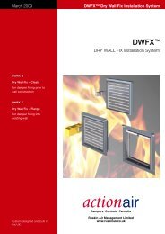
December 2009<br />
<strong>Hot</strong><strong>Shield</strong> <strong>PTC</strong><br />
<strong>Hot</strong><strong>Shield</strong> <strong>PTC</strong> TM<br />
<strong>High</strong> <strong>Operating</strong> <strong>Temperature</strong><br />
<strong>Smoke</strong> Management and Fire Dampers<br />
Features<br />
● <strong>Smoke</strong> Management and Fire<br />
Dampers operational up to<br />
300 °C for a period of 1 or 2<br />
hours (two versions available).<br />
● Thermally insulated electric<br />
Control Modes.<br />
● Pneumatic option available<br />
250 °C for one hour.<br />
● Halogen free low smoke and<br />
fume cabling supplied as a<br />
standard feature.<br />
● Low closed blade leakage.<br />
● Dampers when closed are<br />
compliant to BS 476 Part 20<br />
Fire Damper Test Standard.<br />
● Actionpac Damper Control<br />
System compatibility.<br />
● <strong>Hot</strong><strong>Shield</strong> Vent <strong>PTC</strong> reverse<br />
action dampers for <strong>High</strong><br />
<strong>Operating</strong> <strong>Temperature</strong> <strong>Smoke</strong><br />
Control and Extract<br />
applications.<br />
● <strong>Hot</strong><strong>Shield</strong> Damper Interface<br />
(HDI) enclosure. Unique<br />
<strong>Actionair</strong> Interface heat<br />
protection.<br />
Dampers Designed and Built in Britain
<strong>Hot</strong><strong>Shield</strong> <strong>PTC</strong> TM<br />
Introduction<br />
<strong>Actionair</strong> have developed a new<br />
technically advanced thermal enclosure<br />
that actually has the ability to absorb heat<br />
energy when subjected to a high<br />
temperature environment.<br />
The performance criteria involves<br />
continuous operation of the complete<br />
damper and actuator assembly at<br />
elevated temperatures.<br />
This new enclosure is made from a<br />
phenolic composite resin with excellent<br />
endothermic properties. A chemical<br />
reaction occurs within the insulating<br />
material when it is heated. This reaction<br />
has the effect of lowering the temperature<br />
inside the enclosure, thus prolonging the<br />
duration of the actuator’s operation at<br />
elevated temperatures.<br />
<strong>Smoke</strong> and other products of combustion<br />
kill at least 80% of recorded ‘fire victims’,<br />
smoke is debilitating and can render<br />
people unconscious minimising their<br />
chances of survival. Many more die<br />
weeks or months later from the lingering<br />
effects and toxic effects of smoke<br />
inhalation.<br />
<strong>Smoke</strong> and toxic gases – the Silent<br />
Killers – have to be managed and<br />
controlled quickly and effectively to avoid<br />
confusion and panic from the threat<br />
posed to life safety and the extraction and<br />
control of these deadly gases is of<br />
paramount importance for the safe<br />
evacuation of the buildings occupants.<br />
Application<br />
<strong>Hot</strong><strong>Shield</strong> <strong>PTC</strong> <strong>High</strong> <strong>Operating</strong><br />
<strong>Temperature</strong> <strong>Smoke</strong> Management and<br />
Fire Dampers are designed for installation<br />
in high temperature ductwork systems with<br />
mechanical smoke extraction. As these<br />
ductwork systems regularly serve more<br />
than one fire zone or floor when smoke<br />
extraction is conducted from one area, it is<br />
essential to fully fire protect adjoining fire<br />
zones from ductwork penetrations that are<br />
connected to the smoke extract duct.<br />
For this purpose <strong>Hot</strong><strong>Shield</strong> <strong>PTC</strong><br />
dampers, when closed are a fire rated<br />
damper to BS 476 part 20 for up to 2<br />
hours, thus providing the fire isolation<br />
required. Closure of the damper is<br />
achieved by removal/loss of the electrical<br />
supply. When used for smoke extraction,<br />
under authorised control, the <strong>Hot</strong><strong>Shield</strong><br />
<strong>PTC</strong> damper will remain open under<br />
electrical power for a period of 1 or 2<br />
hours at temperatures of up to 300 °C<br />
thus allowing the safe extraction of smoke<br />
The importance of the subsequent smoke<br />
damage that can occur to adjacent<br />
property and fittings is also recognised,<br />
as this can have disastrous effects on<br />
homes and businesses as recognised in<br />
the Loss Prevention Council Design Guide<br />
for Fire Protection in Buildings.<br />
<strong>Actionair</strong> have developed the <strong>Hot</strong><strong>Shield</strong><br />
<strong>PTC</strong> <strong>High</strong> <strong>Temperature</strong> <strong>Smoke</strong><br />
Management and Fire Dampers along<br />
with the <strong>Hot</strong><strong>Shield</strong> Vent <strong>PTC</strong> <strong>Smoke</strong><br />
Control and Extract Dampers to enable<br />
the concepts of fire engineering to be<br />
employed in ducted smoke ventilation<br />
systems.<br />
These dampers designed, tested and<br />
approved to deliver high temperature<br />
operation at up to 300 °C for 1 and 2<br />
hours, provide the designer with the<br />
capability of extracting hot smoke and<br />
combustion gases through a common<br />
smoke extraction duct linked to adjacent<br />
fire zones and floors.<br />
As smoke can spread rapidly and<br />
efficiently through a building ductwork<br />
system, damper operation needs to be<br />
initiated by a smoke detection system, as<br />
thermal sensing can often be too late.<br />
<strong>Hot</strong><strong>Shield</strong> <strong>PTC</strong> and <strong>Hot</strong><strong>Shield</strong> Vent<br />
<strong>PTC</strong> dampers are designed to be<br />
interfaced with a smoke detection/fire<br />
alarm system.<br />
and hot gases of combustion through the<br />
extended fire compartment created by the<br />
fire rated ductwork.<br />
<strong>Hot</strong><strong>Shield</strong> <strong>PTC</strong> <strong>Smoke</strong> Management Fire<br />
Dampers may also be used for controlled<br />
supply of make up air as a function of the<br />
fire engineering process.<br />
<strong>Hot</strong><strong>Shield</strong> Vent <strong>PTC</strong> <strong>High</strong> <strong>Operating</strong><br />
<strong>Temperature</strong> <strong>Smoke</strong> Control and<br />
Extract Dampers provide flexible smoke<br />
management where other fire<br />
compartments are not interconnected to<br />
a common fire rated ductwork system.<br />
Designed to spring to the open position<br />
by stored energy and remain closed when<br />
powered. <strong>Hot</strong><strong>Shield</strong> Vent <strong>PTC</strong> dampers<br />
allow controlled smoke extraction to take<br />
place with a dedicated smoke control<br />
system if required, but retaining low leak<br />
closure of the smoke extract duct<br />
penetrations into the protected space<br />
during normal conditions.<br />
Casings Features<br />
With double skin spigotted galvanised steel<br />
(to BS EN 10142) casing the <strong>Hot</strong><strong>Shield</strong><br />
<strong>PTC</strong> dampers comply to Class A and B<br />
of Eurovent Document 2/2 and Test<br />
Procedures for Classes A, B and C of<br />
HVCA Ductwork Specification DW144.<br />
Damper casings are manufactured with fully<br />
welded spigotted connections suitable for<br />
Square, Rectangular, Circular and Flat Oval<br />
duct connections. As an extra cost option,<br />
casings can be manufactured in 430<br />
grade (Type 1.4016) Ferritic or 316 grade<br />
(Type 1.4401) Austenitic stainless steel,<br />
1.2mm thick.<br />
Blade Features<br />
The Damper blades are aerodynamic,<br />
double skin 430 grade (Type 1.4016) to BS<br />
EN 10088-2 Ferritic stainless steel which<br />
are 75mm deep and interlock to form a<br />
positive smoke and fire resisting shield.<br />
Incorporated within the blade profile is a<br />
silicone seal to ensure low closed blade<br />
leakage at temperatures up to 300°C for 1<br />
or 2 hours. Stainless steel blade end<br />
bearings and peripheral gasketting maintain<br />
the low closed blade leakage allowing for<br />
expansion under full fire conditions.<br />
Optional Blade construction 316 grade (Type<br />
1.4401) Austenitic Stainless Steel.<br />
Proportional Torque<br />
Control<br />
A new generation <strong>High</strong> <strong>Operating</strong><br />
<strong>Temperature</strong> <strong>Smoke</strong> Management and Fire<br />
Damper, thermally Insulated Control Mode<br />
assembly, with a unique and dedicated<br />
Proportional Torque Control for optimised<br />
Damper/Control Mode torque<br />
performance. The unique snaplock drive<br />
interface ensures user friendly, easy and<br />
secure connection of the Control Mode to<br />
the damper. The drive interface, which is<br />
totally independent of the ductwork, and<br />
provides ease of connection to square,<br />
rectangular, circular and flat oval<br />
ductwork, including fire rated Ductwork.<br />
Parameters<br />
<strong>Hot</strong><strong>Shield</strong> <strong>PTC</strong> and <strong>Hot</strong><strong>Shield</strong> Vent<br />
<strong>PTC</strong> Dampers to maximum width and<br />
height dimensions (see page 6) can be<br />
used where the operating total system<br />
pressure is up to 1500 Pascals and duct<br />
velocities to 15m/second.<br />
As with any life safety damper product, a<br />
suitable planned inspection programme<br />
should be implemented. For specialist<br />
and/or aggressive applications, please<br />
refer to <strong>Actionair</strong> Sales Office.<br />
2 www.actionair.co.uk
<strong>Hot</strong><strong>Shield</strong> <strong>PTC</strong> TM<br />
Control Options<br />
A choice of a 24V or 230V Control Modes<br />
located outside the ductwork and<br />
(protected by its own thermally insulated<br />
enclosure) and Halogen Free Low <strong>Smoke</strong><br />
and Fume cables, allows <strong>Hot</strong><strong>Shield</strong><br />
<strong>PTC</strong> Damper control up to 300 °C for a<br />
period of 1 or 2 hours.<br />
The Control Mode upon receipt of the<br />
relevant supply voltage will motor the<br />
Damper to the open position. Closure of<br />
the Damper is achieved by removal/loss<br />
of the electrical supply.<br />
The Damper when closed will provide<br />
protection in accordance with BS 476<br />
Part 20. Control Modes have two<br />
separate volt free contacts for the<br />
provision of external damper status<br />
indication. (No thermal links available).<br />
<strong>Hot</strong><strong>Shield</strong> Vent <strong>PTC</strong> Dampers and<br />
associated Control Modes are reverse<br />
action with spring opening.<br />
<strong>Hot</strong><strong>Shield</strong> and <strong>Hot</strong>/Vent/<strong>Shield</strong><br />
HM5 <strong>PTC</strong> 10W (12.5VA) 24V end switches SPDT 250V 6(3)A <strong>Hot</strong><strong>Shield</strong> Power Off – Fail-safe Close ■<br />
HM6 <strong>PTC</strong> 12W (14VA) 230V end switches SPDT 250V 6(3)A <strong>Hot</strong><strong>Shield</strong> Power Off – Fail-safe Close ■<br />
HMV5 <strong>PTC</strong> Vent 1 10W (12.5VA) 24V end switches SPDT 250V 6(3)A <strong>Hot</strong>/Vent<strong>Shield</strong> Power Off – Fail-safe Open ■<br />
HMV6 <strong>PTC</strong> Vent 12W (14VA) 230V end switches SPDT 250V 6(3)A <strong>Hot</strong>/Vent<strong>Shield</strong> Power Off – Fail-safe Open ■<br />
HM5-2H <strong>PTC</strong> 10W (12.5VA) 24V end switches SPDT 250V 6(3)A <strong>Hot</strong><strong>Shield</strong> Power Off – Fail-safe Close ■<br />
HM6-2H <strong>PTC</strong> 12W (14VA) 230V end switches SPDT 250V 6(3)A <strong>Hot</strong><strong>Shield</strong> Power Off – Fail-safe Close ■<br />
HMV5-2H <strong>PTC</strong> Vent 10W (12.5VA) 24V end switches SPDT 250V 6(3)A <strong>Hot</strong>/Vent<strong>Shield</strong> Power Off – Fail-safe Open ■<br />
HMV6-2H <strong>PTC</strong> Vent 12W (14VA) 230V end switches SPDT 250V 6(3)A <strong>Hot</strong>/Vent<strong>Shield</strong> Power Off – Fail-safe Open ■<br />
■ ■ See wiring detail on page 4.<br />
<strong>Hot</strong><strong>Shield</strong> and <strong>Hot</strong>/Vent<strong>Shield</strong> Control Modes HM5 <strong>PTC</strong> and HM6 <strong>PTC</strong> (operational for 1 hour @ 300 °C) and HM5 – 2H <strong>PTC</strong> and HM6 – 2H <strong>PTC</strong><br />
(operational for 2 hours @ 300 °C) are NOT supplied with the Electrical Thermal Release (ETR). They Fail-safe when the power is off/interrupted).<br />
<strong>Hot</strong><strong>Shield</strong> and <strong>Hot</strong>/Vent<strong>Shield</strong><br />
HM5-3P <strong>PTC</strong> 24V 7W (10VA) end switches SPDT 250V 6(3)A <strong>Hot</strong><strong>Shield</strong> Power Off – Fail-safe Close 2-10V Set position<br />
HMV5-3P <strong>PTC</strong> Vent 24V 7W (10VA) end switches SPDT 250V 6(3)A <strong>Hot</strong>/Vent<strong>Shield</strong> Power Off – Fail-safe Open 2-10V Set position<br />
<strong>Hot</strong><strong>Shield</strong> and <strong>Hot</strong>/Vent<strong>Shield</strong> Control Modes HM5 – 3P <strong>PTC</strong> (operational for 1 hour @ 300 °C) are NOT supplied with<br />
Electrical Thermal Release (ETR) and Fail-safe when the power is off/interrupted. NOTE: 1 hour version only available.<br />
<strong>Hot</strong><strong>Shield</strong> and <strong>Hot</strong>/Vent<strong>Shield</strong> 2 Position Drive Open / Drive Closed<br />
HM5-2P <strong>PTC</strong> 24V 7W (10VA), end switches SPDT 250V 6(3)A<br />
HM6-2P <strong>PTC</strong> 230V 8W (12.5VA), end switches SPDT 250V 6(3)A<br />
HM5-2P and HM6-2P are NOT supplied with ETR and remain in the desired emergency position<br />
when power is interrupted. (Operational for 1 hour at 300°C).<br />
HM9 <strong>PTC</strong> Pneumatic Air Off –<br />
Fail-safe Close<br />
HMV9 <strong>PTC</strong> Vent Pneumatic Air Off –<br />
Fail-safe Open<br />
Pneumatic version rated at 250 °C for 1 hour.<br />
Damper/Control<br />
Mode Interface<br />
Position 1<br />
Vertically down<br />
Position 2 Horizontal<br />
Supplied as standard<br />
Position 3<br />
Vertically up<br />
<strong>Hot</strong><strong>Shield</strong> <strong>PTC</strong> Damper with unique<br />
snaplock Damper/Control Mode<br />
Interface<br />
The <strong>Actionair</strong> unique snaplock drive<br />
interface ensures user friendly, easy and<br />
secure connection of the Control Mode to<br />
the damper.<br />
The drive interface which is totally<br />
independent of the ductwork, eliminates<br />
the need for costly dedicated duct<br />
sections, and provides ease of connection<br />
to square, rectangular, circular and flat<br />
oval ductwork.<br />
The drive interface can be used up to wall<br />
thicknesses of 250mm. The interface<br />
allows the Control Modes be fitted in any<br />
one of three orientations i.e.<br />
Vertically down, Position 1<br />
Horizontally, Position 2, (standard) or<br />
Vertically up, Position 3.<br />
This can be simply and easily carried out<br />
on site, by the using <strong>Actionair</strong> “multi<br />
positions kit”. Full details on see pages<br />
10 and 11) This flexibility ensures that the<br />
damper and control mode require the<br />
minimal amount of room.<br />
This drive interface also guarantees that<br />
only the correct and certified <strong>Actionair</strong><br />
products can be used.<br />
www.actionair.co.uk<br />
3
<strong>Hot</strong><strong>Shield</strong> <strong>PTC</strong> TM<br />
Application and Wiring<br />
Mode HM5 (24V System) and HM5 2H<br />
Supply On – Damper motors open.<br />
Supply Off – Spring closure.<br />
Cable specification:<br />
Si HF Low <strong>Smoke</strong> and Fume, Halogen<br />
Free, to IEC 754-1. Conforming to<br />
73/23/EEC directive.<br />
Release Time ≈ 22 secs.<br />
Reset Time ≈ 60 secs.<br />
(Connect 24V via a safety isolating<br />
transformer.)<br />
IP54 Rated<br />
AC/DC 24V<br />
50 1 / 60 Hz<br />
12.5 VA<br />
10/2 W<br />
Imax<br />
8.3A @ 5ms<br />
–30...+50 C<br />
CONTINUOUS<br />
AC<br />
250V<br />
6(3)A<br />
M<br />
1<br />
2<br />
1<br />
2<br />
3<br />
4<br />
–<br />
+<br />
SUPPLY<br />
24V AC or DC<br />
VOLT FREE CONTACT<br />
CLOSED WHEN<br />
DAMPER RELEASED<br />
VOLT FREE CONTACT<br />
CLOSED WHEN<br />
DAMPER RESET<br />
Mode HM6 (230V System) and HM6 2H<br />
Supply On – Damper motors open.<br />
Supply Off – Spring closure.<br />
Cable specification:<br />
Si HF Low <strong>Smoke</strong> and Fume, Halogen<br />
Free, to IEC 754-1. Conforming to<br />
73/23/EEC directive.<br />
Release Time ≈ 22 secs.<br />
Reset Time ≈ 60 secs.<br />
(To isolate from main power supply, the system must<br />
incorporate a device which disconnects the phase<br />
conductors, with a least 3mm contact gap.)<br />
IP54 Rated<br />
AC 230V<br />
50 / 60 Hz<br />
14 VA<br />
12/4 W<br />
– 30...+50 C<br />
CONTINUOUS<br />
AC<br />
250V<br />
6(3)A<br />
M<br />
BLUE<br />
BROWN<br />
N<br />
L1<br />
1<br />
2<br />
3<br />
4<br />
SUPPLY<br />
230V AC 50/60 Hz<br />
VOLT FREE CONTACT<br />
CLOSED WHEN<br />
DAMPER RELEASED<br />
VOLT FREE CONTACT<br />
CLOSED WHEN<br />
DAMPER RESET<br />
Multiple Assemblies<br />
LHD<br />
STD<br />
RHD<br />
LHD<br />
Square and rectangular casings are<br />
available in multiple module<br />
arrangements, supplied complete with<br />
blanking strips for site assembly by<br />
others. Additional support as well as<br />
provision for thermal expansion<br />
(4mm/metre) should be allowed for on<br />
multiple assemblies.<br />
STD<br />
RHD<br />
STD<br />
RHD<br />
PLAN VIEW<br />
LHD<br />
LHD<br />
STD<br />
RHD<br />
STD<br />
RHD<br />
PLAN VIEW<br />
Multiple assemblies require installation<br />
approval by the relevant local authority.<br />
STD<br />
RHD<br />
LHD<br />
STD<br />
RHD<br />
Approximate Weights (kg)<br />
Square or Circular 100 150 200 250 300 350 400 450 500 550 600 650 70 750 850 850 900 950 1000<br />
Duct Size (mm)<br />
Series 2501 Square 3.4 3.4 3.4 4.2 4.8 5.6 6.5 7.4 8.6 9.6 10.8 12.4 13.6 14.9 16.2 17.7 19.2 20.8 23.5<br />
Series 2501 Square 6.2 6.2 6.2 7.4 8.7 10.3 11.9 13.2 14.6 16.3 18.5 20.5 22.1 24.0 25.9 28.1 30.3 32.4 34.5<br />
+ Installation Frame<br />
Series 2601 Circular 5.3 5.3 5.3 6.1 7.2 8.4 9.6 11.2 12.6 14.0 15.9 17.5 19.1 20.7 22.5 24.3 26.2 29.3 32.1<br />
Series 2601 Circular 8.5 8.5 8.5 10.0 11.9 13.7 15.4 17.1 19.2 21.8 24.0 26.0 28.2 30.4 32.8 35.3 37.8 40.3 43.1<br />
+ Installation Frame<br />
Control Modes 5 and 6 7.6 Kg (including drive interface)<br />
4 www.actionair.co.uk
<strong>Hot</strong><strong>Shield</strong> <strong>PTC</strong> TM<br />
<strong>Hot</strong><strong>Shield</strong> Damper Interface Enclosure (HDI)<br />
Sectional View of HDI Enclosure<br />
HDI Enclosue Lid<br />
Special Thermal<br />
Insulating Material<br />
HSFDI<br />
<strong>Actionair</strong> have developed a unique thermal<br />
enclosure to protect the Actionpac LNS<br />
range of damper interfaces currently<br />
available.<br />
The enclosure consists of two separate<br />
materials, enabling the HDI to function at<br />
the extreme temperature specified. The<br />
outer casing has endothermic properties<br />
that significantly slow down the internal<br />
temperature rise in a high temperature<br />
emergency condition. The inner casing is<br />
a special thermal insulating material.<br />
The maximum temperature is 300°C for<br />
up to one hour. This has been tested and<br />
independently witnessed by BRE (Ref Test<br />
No. 221067A).<br />
The HDI enclosure is to be used in<br />
<strong>Hot</strong><strong>Shield</strong> <strong>PTC</strong> applications where the<br />
Actionpac LNS system is being used to<br />
control the dampers.<br />
Dimensions<br />
20<br />
360 4 off 6mm<br />
diameter<br />
holes<br />
SFDI Unit<br />
SFDIs and SDIs, can be installed within<br />
the HDI enclosure.<br />
The HDI can be mounted in any orientation,<br />
on a flat surface or alternative suitable<br />
mounting system.<br />
The SFDI, or SDI units are supplied<br />
without the damper interface electronics,<br />
which will be supplied separately at<br />
commissioning stage.<br />
Maximum normal external operating<br />
temperature: 30°C.<br />
Total Weight (including internal DIs) =<br />
11.5Kg (approx).<br />
396<br />
HDI Enclosue<br />
Base<br />
Typical Installation<br />
Endothermic Thermal<br />
Insulating Material<br />
1. Fix the 2 off mounting brackets provided,<br />
to the underside of the HDI enclosure, by<br />
screwing into the threaded inserts with<br />
the M5 screws provided.<br />
2. Allowing suitable cable access around<br />
the HDI enclosure, position it in desired<br />
location, and mark fixings positions using<br />
the bracket holes as a template.<br />
3. Remove HDI enclosure lid by unscrewing<br />
the 6 off long screws/large flat washers<br />
4. Securely mount the HDI base in its<br />
intended position. Hole specification and<br />
fixings by others.<br />
5. Remove DI/CMS lid.<br />
6. Connect cables and refit DI lid in<br />
accordance with Actionpac catalogue<br />
information.<br />
Mounting<br />
Bracket<br />
7. Refit HDI enclosure lid with the 6 off<br />
screws/large flat washers, taking care to<br />
position cables in grooves. The inside<br />
insulation is sufficiently soft to compress<br />
locally around cables when the lid is<br />
screwed down.<br />
316<br />
6 off<br />
M5 x 130mm<br />
screws<br />
113<br />
Note: HDI lid may need to be removed and<br />
refitted again during testing/commissioning.<br />
235<br />
384<br />
www.actionair.co.uk<br />
5
<strong>Hot</strong><strong>Shield</strong> <strong>PTC</strong> TM<br />
Installation Systems<br />
Popular types of Installation Frame that<br />
are available.<br />
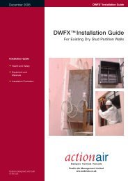
DWFX TM (DRY WALL FIX) Installation<br />
System<br />
Typically for installation into Dry Wall, Stud<br />
Partitions.<br />
HEVAC / HVCA Galvanised Steel<br />
Installation Frames<br />
Typically for installation into Blockwork,<br />
Concrete walls and floors.<br />
DWFX-F (Dry Wall FiX - Frame)<br />
DWFX-C (Dry Wall FiX - Cleat)<br />
DWFX-F Dimensional Data<br />
See page 8 and 9.<br />
DWFX-C Dimensional Data<br />
50 50 50<br />
Specification<br />
The <strong>Actionair</strong> DWFX-F installation method<br />
is BRE assessed to BS476 Pt 20/22 for<br />
90 minutes (BRE assessment no.<br />
225283).<br />
The <strong>Actionair</strong> DWFX-F consists of a 1.2<br />
mm galvanised steel peripheral flange<br />
with 50mm x 50mm x 3mm steel angle<br />
cleats with 14mm x 24mm oval slots,<br />
welded to damper casing for drop rod<br />
support.<br />
Specification<br />
The <strong>Actionair</strong> DWFX-C consists of 50mm<br />
x 50mm x 3mm steel angle cleats with<br />
14mm x 24mm oval slots.<br />
Fully welded to damper casing for drop<br />
rod support prior to wall construction.<br />
24<br />
14<br />
Comprehensive literature, outlining<br />
installation and features, is available for our<br />
DWFX systems. Go to our website:-<br />
www.actionair.co.uk<br />
to view or download these as PDF files.<br />
6 www.actionair.co.uk
<strong>Hot</strong><strong>Shield</strong> <strong>PTC</strong> TM 7<br />
HEVAC / HVCA Galvanised Steel Installation Frames<br />
Galvanised steel building<br />
ties permit stable<br />
handling, ease of<br />
transport and<br />
convenience of building in<br />
to the surrounding<br />
structure.<br />
Galvanised Steel Installation Frames<br />
(as required by HVC 6/5/83 Rev.1 July<br />
1999.)<br />
Installation frames are delivered to site as a<br />
complete assembly with the appropriate<br />
Damper fitted therein. The frame shall be<br />
installed centrally in the thickness of a<br />
brick, blockwork or concrete surrounding<br />
wall or floor, or in the case of thick walls or<br />
floors, so that the centre line of the frame<br />
is at least 50mm away from the nearest<br />
face of the wall or floor in which the<br />
assembly is mounted. The four tabs<br />
(building tie) forming each fixing point<br />
shall provide a positive fixing into the<br />
structure. Multiple assembly dampers up<br />
to 1500 x 1500 or 2000 x 1000 can be<br />
fitted into fully assembled installation<br />
frames and delivered as one piece.<br />
Dampers in excess of these sizes will be<br />
supplied in sections with the installation<br />
frame supplied in kit-form, Drg AA/F/8057.<br />
This drawing and method statement will be<br />
supplied for assembly to on site.<br />
The maximum size of kit-form installation<br />
frames is 2500mm wide x 2000mm high.<br />
a. In brick or blockwork walls the tabs shall<br />
be bent out and solidly built into the mortar<br />
joints between the brick or blockwork.<br />
b. In the case of reinforced concrete walls<br />
and floors, the tabs shall be bent out and<br />
tied with wire to the reinforcing bars which<br />
will be deliberately left protruding into the<br />
opening.<br />
The gap between the installation frame<br />
and builders work shall be backfilled<br />
with mortar or concrete on both sides<br />
of the flange.<br />
Adjacent frame assemblies must be<br />
separated by builders work of a minimum<br />
thickness of 225mm (between installation<br />
frame upstand flanges) unless approval<br />
has been previously obtained from the<br />
appropriate Authority. For installations<br />
below this dimension please refer to<br />
<strong>Actionair</strong> Sales office.<br />
In no case shall the HEVAC/HVCA frame<br />
and damper assembly be held in position<br />
merely by the adjacent ductwork, and it<br />
should be noted that in reinforced concrete<br />
structures (especially floors), it will not be<br />
sufficient to only backfill between the<br />
damper installation frame and the<br />
surrounding opening with mortar or fine<br />
aggregate concrete mix without provision<br />
for tying in the frame to the surrounding<br />
reinforced concrete structure.<br />
Approved Installations<br />
A binder containing approved installation<br />
illustrations is now available.<br />
Refer to <strong>Actionair</strong> Sales Office or visit<br />
our website, www.actionair.co.uk<br />
The illustrations are under the heading<br />
PRODUCTS DRAWINGS.<br />
Although the included methods have been<br />
tested and assessed, it is recommend,<br />
that these, as with all installation methods<br />
must be confirmed with Building Control /<br />
Local Authority prior to manufacture.<br />
<strong>Actionair</strong> can also provide applications of<br />
other proposed methods of installation,<br />
please contact our Sales Office to discuss<br />
your specific requirements.<br />
These again are the responsibility of the<br />
client to ensure that these are acceptable to<br />
Building Control / Local Authority before<br />
construction commences.<br />
www.actionair.co.uk
<strong>Hot</strong><strong>Shield</strong> <strong>PTC</strong> TM<br />
Dimensional Data<br />
For Rectangular Dampers spigots are 5mm under duct size.<br />
* Widths and heights available in 1mm increments.<br />
Basic Dampers<br />
Dampers with Installation Systems<br />
Dampers with DWFX-F<br />
HEVAC / HVCA IF<br />
Rectangular Dampers Series 2501 and 3501<br />
For Ducts with widths of 100 – 150mm<br />
For Ducts with heights<br />
of 100 – 150mm<br />
OVERALL FLANGE WIDTH = 370mm<br />
OVERALL FLANGE HEIGHT = 395mm<br />
OVERALL WIDTH OF INSTALLATION<br />
FRAME IS 316mm<br />
OVERALL HEIGHT OF INSTALLATION<br />
FRAME IS 340mm<br />
25 = 100 - 150 =<br />
DUCT WIDTH<br />
25<br />
50<br />
90<br />
25<br />
50<br />
50<br />
25<br />
DUCT HEIGHT<br />
83<br />
25 = 151 - 199 = 25<br />
25 200 -1000<br />
25<br />
200 - 1000<br />
200<br />
For Ducts with widths of 151 – 199mm<br />
50<br />
110<br />
25<br />
DUCT WIDTH<br />
250<br />
DUCT WIDTH<br />
DUCT<br />
HEIGHT<br />
100 - 150<br />
DUCT<br />
HEIGHT<br />
151 - 199<br />
For Ducts with widths and heights of 200 – 1000mm<br />
28<br />
28<br />
28<br />
DUCT HEIGHT<br />
200 - 1000<br />
38 38 78<br />
38 38 78<br />
38 38<br />
38 38<br />
200 - 1000 250<br />
200<br />
For Ducts with heights<br />
of 151 – 199mm<br />
38 78<br />
38<br />
OVERALL FLANGE WIDTH = 420mm<br />
OVERALL FLANGE HEIGHT = 445mm<br />
50<br />
OVERALL FLANGE WIDTH<br />
= DUCT WIDTH + 170mm<br />
OVERALL FLANGE HEIGHT<br />
= DUCT HEIGHT + 195mm<br />
50<br />
85 200<br />
110<br />
250<br />
85<br />
110<br />
200 - 1000<br />
85<br />
200<br />
57<br />
OVERALL WIDTH OF INSTALLATION<br />
FRAME IS 366mm<br />
OVERALL HEIGHT OF INSTALLATION<br />
FRAME IS 390MM<br />
83<br />
57 250<br />
90<br />
OVERALL WIDTH OF INSTALLATION<br />
FRAME IS DUCT WIDTH + 116mm<br />
OVERALL HEIGHT OF INSTALLATION<br />
FRAME IS DUCT HEIGHT + 140MM<br />
83<br />
57 200 - 1000<br />
90<br />
8 www.actionair.co.uk
<strong>Hot</strong><strong>Shield</strong> <strong>PTC</strong> TM<br />
For Circular and Flat Oval Dampers spigots are 3mm under duct size.<br />
Basic Dampers<br />
Dampers with Installation Systems<br />
Dampers with DWFX-F<br />
HEVAC / HVCA IF<br />
Circular Dampers Series 2601 and 3601<br />
=<br />
DUCT DIA<br />
100 - 150<br />
=<br />
50<br />
OVERALL FLANGE WIDTH = 370mm<br />
OVERALL FLANGE HEIGHT = 395MM<br />
50<br />
OVERALL WIDTH OF INSTALLATION<br />
FRAME IS 316mm<br />
OVERALL HEIGHT OF INSTALLATION<br />
FRAME IS 340mm<br />
90<br />
=<br />
25<br />
DUCT<br />
DIAMETER<br />
100 - 150<br />
108<br />
28<br />
200<br />
CIRCULAR<br />
CIRCULAR<br />
=<br />
25<br />
200<br />
25<br />
25<br />
25<br />
65 38 78<br />
38<br />
65<br />
85<br />
82<br />
DUCT DIA<br />
=<br />
151 - 199<br />
=<br />
OVERALL FLANGE WIDTH = 420mm<br />
OVERALL FLANGE HEIGHT = 445mm<br />
OVERALL WIDTH OF INSTALLATION<br />
FRAME IS 366mm<br />
OVERALL HEIGHT OF INSTALLATION<br />
FRAME IS 390mm<br />
90<br />
DUCT<br />
= DIAMETER =<br />
151 - 199<br />
25 250<br />
28<br />
25<br />
50<br />
25 250<br />
25<br />
25 CIRCULAR<br />
CIRCULAR<br />
110<br />
85<br />
108<br />
82<br />
65 38 78<br />
38<br />
65<br />
50<br />
DUCT DIA<br />
50<br />
200 - 950<br />
OVERALL FLANGE WIDTH =<br />
DUCT DIA. + 220mm<br />
OVERALL FLANGE HEIGHT =<br />
DUCT DIA. + 245mm<br />
50<br />
OVERALL WIDTH OF INSTALLATION<br />
FRAME IS DUCT DIA + 166mm<br />
OVERALL HEIGHT OF INSTALLATION<br />
FRAME IS DUCT DIA + 190mm<br />
90<br />
DUCT<br />
DIAMETER<br />
50<br />
75<br />
50<br />
25<br />
110<br />
108<br />
110<br />
50<br />
200 - 950<br />
25 Duct<br />
28<br />
25<br />
25 Duct<br />
DIA + 50mm*<br />
25 CIRCULAR<br />
CIRCULAR<br />
85<br />
82<br />
FOR 951 – 1000mm<br />
DUCT DIM + 30mm<br />
65 38 78<br />
38<br />
65<br />
Flat Oval Dampers Series 2701 and 3701<br />
50 DUCT WIDTH * 50<br />
300 – 950<br />
75<br />
50<br />
25<br />
OVERALL FLANGE WIDTH =<br />
DUCT WIIDTH + 220mm<br />
OVERALL FLANGE HEIGHT =<br />
DUCT HEIGHT + 245mm<br />
50<br />
110<br />
OVERALL WIDTH OF INSTALLATION<br />
FRAME IS DUCT WIDTH + 166mm<br />
OVERALL HEIGHT OF INSTALLATION<br />
FRAME IS DUCT HEIGHT +190mm<br />
90<br />
108<br />
DUCT<br />
HEIGHT<br />
50<br />
200 - 500<br />
25 DUCT WIDTH + 50mm* 25<br />
28<br />
25 DUCT HEIGHT<br />
+50MM<br />
25 FLAT OVAL<br />
65 38 78<br />
38 65<br />
FLAT OVAL<br />
85<br />
82<br />
FOR 951 – 1000mm<br />
DUCT DIM + 30mm<br />
*<br />
www.actionair.co.uk<br />
9
<strong>Hot</strong><strong>Shield</strong> <strong>PTC</strong> TM<br />
Damper Installation and Control Mode Fitting<br />
The <strong>Actionair</strong> unique snaplock drive<br />
interface ensures user friendly, easy and<br />
secure connection of the control mode to<br />
the damper.<br />
The drive interface can be used up to wall<br />
thicknesses of 250mm. The drive<br />
interface allows the control modes to be<br />
fitted in any one of three orientations i.e.<br />
Vertically down, Position 1<br />
Horizontally, Position 2, (standard) or<br />
Vertically up, Position 3.<br />
A “multi positions kit” is required for<br />
positions 1 and 3 ( for position 2 the<br />
“multi positions kit”is optional).<br />
DAMPER<br />
DRIVE<br />
SHROUD<br />
TRANSIT<br />
PLATE<br />
THERMAL<br />
ENCLOSURE<br />
ASSEMBLY<br />
EASY PULL<br />
LEVER KEY<br />
RING<br />
Typical Installation<br />
1. Install the <strong>Hot</strong><strong>Shield</strong> <strong>PTC</strong> Damper,<br />
complete with factory fitted damper shroud<br />
and transit plate, into the structure.<br />
2. Connect and fit ductwork to damper<br />
spigots.<br />
3. Remove transit plate and discard<br />
(recycle).<br />
4. Slide the snaplock drive interface into<br />
the damper drive shroud. Pull the key ring<br />
on the easy pull lever, this snaplocks the<br />
drive Interface into position.<br />
Care must be taken when back filling to<br />
ensure that the snaplock retaining pin<br />
location hole and the entry slot of the<br />
damper drive shroud is clear of builders<br />
work debris.<br />
HDI<br />
Changing the Control Mode of the<br />
<strong>Hot</strong><strong>Shield</strong> <strong>PTC</strong> to position 1 and 3<br />
on site:<br />
DAMPER<br />
SHROUD<br />
MOUNTING<br />
FLANGES<br />
KEY RING ON THE<br />
EASY PULL LEVER<br />
1. Remove the 4 off M6 bolts and<br />
washers, lift off the thermal enclosure<br />
assembly,<br />
2. Rotate the interface input shaft fully<br />
anti-clock wise.<br />
3. Line up the output shaft slot on the<br />
underside of the interface with the slot on<br />
the interface plate.<br />
4. Locate the thermal enclosure assembly<br />
to desired position and fix it to the<br />
mounting flanges with M6 bolts and<br />
washers.<br />
5. Fully close the damper.<br />
6. Pull the key ring on the easy pull lever,<br />
insert the interface assembly into the<br />
damper shroud, line up its dotted line with<br />
the end of the shroud, release the lever to<br />
lock.<br />
7. Refer to standard O+M for testing.<br />
INTERFACE<br />
INPUT SHAFT<br />
Reverse Mounting<br />
The thermal enclosure<br />
and control mode can<br />
be reverse mounted<br />
using the “multi<br />
positions kit” onto the<br />
<strong>Hot</strong><strong>Shield</strong> <strong>PTC</strong><br />
M6 BOLTS +<br />
WASHERS<br />
THERMAL<br />
ENCLOSURE<br />
ASSEMBLY<br />
The information contained herein is subject to change<br />
without notice due to continuing research and<br />
development.<br />
10 www.actionair.co.uk
<strong>Hot</strong><strong>Shield</strong> <strong>PTC</strong> TM<br />
Damper, Interface and Thermal Enclosure Dimensions<br />
Note:<br />
For <strong>Hot</strong><strong>Shield</strong> <strong>PTC</strong>, the control mode<br />
with the horizontal position 2 (without<br />
multi positions kit), will be standard,<br />
unless stated, otherwise this is the default<br />
option.<br />
A multi positions kit for position 1. 2<br />
and 3 is available. If the multi positions<br />
option is required, the control mode is<br />
sent out to position 2. It is easy to change<br />
to position 1 or 3 on site.<br />
Maintenance<br />
The <strong>Hot</strong><strong>Shield</strong> <strong>PTC</strong> Dampers are<br />
designed for applications in normal dry<br />
filtered air systems and should be<br />
subjected to a planned inspection<br />
programme, with cleaning and light oil<br />
lubrication in accordance with BS9999.<br />
When exposed to fresh air intakes<br />
and/or inclement conditions this may<br />
need to be performed more regularly<br />
based on experience gained from<br />
previous inspections.<br />
www.actionair.co.uk<br />
11
<strong>Hot</strong><strong>Shield</strong> <strong>PTC</strong> TM<br />
Acoustic Data<br />
The data presented is from the<br />
Laboratory Determination of Acoustic and<br />
Aerodynamic Performance of <strong>Hot</strong><strong>Shield</strong><br />
<strong>PTC</strong> <strong>High</strong> <strong>Operating</strong> <strong>Temperature</strong><br />
<strong>Smoke</strong> Management and Fire Dampers.<br />
A programme of extensive tests was<br />
carried out in the Reverberation Chamber<br />
and North Transmission Chamber of<br />
Sound research Laboratories Limited,<br />
Holbrook Hall, Sudbury, Suffolk, generally<br />
in accordance with BRITISH STANDARDS<br />
Nos. 4196, 4773, 4856, 4857 and 4954.<br />
This independent test facility is approved<br />
under the NAMAS Scheme.<br />
From the selection of a duct velocity<br />
within the operational parameters of the<br />
damper a resultant pressure drop from<br />
Table 1 can be determined and the sum<br />
of these two components applied to the<br />
Velocity x Pressure Drop Vs Sound Power<br />
Level Graph. (Table 2)<br />
The graph is the result of a full<br />
range of acoustic tests on <strong>Hot</strong><strong>Shield</strong><br />
<strong>PTC</strong> <strong>High</strong> <strong>Operating</strong> <strong>Temperature</strong><br />
<strong>Smoke</strong> Management and Fire Dampers<br />
with the blades set in then fully open<br />
position.<br />
The Spectrum Correction Data is applied<br />
to the number obtained from the graph<br />
and a complete Sound Spectrum of Flow<br />
Generated Noise for both Outlet (in duct)<br />
and Breakout (casing radiated) is<br />
obtained.<br />
Example:<br />
Duct with a design velocity of<br />
8 m/sec. <strong>Hot</strong><strong>Shield</strong> <strong>PTC</strong> Damper Series<br />
2501 fully open.<br />
Pressure Drop = 22 Pa (Table 1).<br />
Multiply Velocity x Pressure Drop<br />
8 x 22 = 176.<br />
From Sound Power Graph (Table 2) plot<br />
176 on horizontal Velocity/Pressure axis<br />
against 2501 outlet (induct) graph to<br />
obtain 47 dBW on Vertical Sound Power<br />
Level Axis. Add or subtract corrections to<br />
the 47 dBW to provide full spectrum<br />
analysis.<br />
Velocity (m/s) X Pressure Drop (Pa) Vs Sound Power Level (dBW)<br />
90<br />
Pressure Drop Vs Velocity<br />
PRESSURE DROP (Pa)<br />
100<br />
90<br />
80<br />
70<br />
60<br />
50<br />
40<br />
30<br />
20<br />
10<br />
987<br />
6<br />
5<br />
4<br />
3<br />
2<br />
EXAMPLE LINE<br />
TYPE 2501<br />
TYPE 2601<br />
1<br />
1 2 3 4 5 6 7 8 9 10 15<br />
Table 1<br />
VELOCITY (m/s)<br />
Damper Leakage<br />
<strong>Hot</strong><strong>Shield</strong> <strong>PTC</strong> and<br />
<strong>Hot</strong><strong>Shield</strong> Vent <strong>PTC</strong> closed blade<br />
leakage as tested on a damper 1000mm<br />
wide x 1000mm high.<br />
Leakage Data at Ambient <strong>Temperature</strong><br />
(Cold <strong>Smoke</strong>).<br />
15001<br />
SOUND POWER LEVEL (dBW)<br />
80<br />
70<br />
60<br />
50<br />
40<br />
30<br />
20<br />
EXAMPLE LINE<br />
2501 BREAKOUT<br />
2601 BREAKOUT<br />
2601 OUTLET (INDUCT)<br />
2501 OUTLET (INDUCT)<br />
PRESSURE DIFFERENTIAL ACROSS CLOSED DAMPER (Pa)<br />
1000<br />
900<br />
800<br />
700<br />
600<br />
500<br />
400<br />
300<br />
200<br />
100<br />
90<br />
80<br />
70<br />
60<br />
50<br />
40<br />
30<br />
10<br />
20<br />
0<br />
Table 2<br />
10<br />
20<br />
30<br />
40<br />
50<br />
60<br />
70<br />
80<br />
90<br />
100<br />
200<br />
300<br />
400<br />
500<br />
600<br />
700<br />
800<br />
900<br />
1000<br />
VELOCITY X PRESSURE DROP (m/s Pa)<br />
2000<br />
3000<br />
4000<br />
5000<br />
6000<br />
7000<br />
8000<br />
9000<br />
10000<br />
10<br />
5 6 7 8 9 10 20 30 40 60 80 100<br />
50 70 90<br />
Table 3<br />
LEAKAGE (I/s)<br />
<strong>Hot</strong><strong>Shield</strong> <strong>PTC</strong> Outlet (Induct) Spectrum<br />
Corrections<br />
Octave Band63 125 250 500 1k 2k 4k 8k<br />
Series 2501 +5 +4 +5 +5 +3 +1 -3 -5<br />
Series 2601 +9 +4 +4 +5 +3 +1 -3 -6<br />
<strong>Hot</strong><strong>Shield</strong> <strong>PTC</strong> Breakout Spectrum<br />
Corrections<br />
63 125 250 500 1k 2k 4k 8k Hz<br />
+8 +11 +9 +6 -3 -6 -14 -17 dB<br />
+6 +10 +8 +4 -3 -3 -11 -14 dB<br />
The leakage as detailed in Table 3 was<br />
achieved after a total immersion test at<br />
300 °C for 1 hour (as witnessed by the<br />
Loss Prevention Council).<br />
12 www.actionair.co.uk
<strong>Hot</strong><strong>Shield</strong> <strong>PTC</strong> TM<br />
Specification<br />
Approvals<br />
<strong>Hot</strong><strong>Shield</strong> <strong>PTC</strong> <strong>High</strong> <strong>Operating</strong><br />
<strong>Temperature</strong> <strong>Smoke</strong> Management and<br />
Fire Dampers comprising of 75mm<br />
stainless steel aerodynamic interlocking<br />
blades incorporating synthetic seal, with<br />
stainless steel blade end bearings and<br />
peripheral gasketing. Housed in a<br />
galvanised fully welded, spigotted casing<br />
suitable for square, rectangular, circular or<br />
flat oval connections.<br />
The totally enclosed precise movement<br />
opposed blade drive shall be positioned<br />
out of the airstream for protection against<br />
damage, be hard wearing and free running.<br />
The Control Mode/Damper connection<br />
shall be by means of the snaplock drive<br />
interface mechanism, which is totally<br />
independent of the ductwork.<br />
<strong>Hot</strong><strong>Shield</strong> <strong>PTC</strong> <strong>High</strong> <strong>Operating</strong><br />
<strong>Temperature</strong> <strong>Smoke</strong> Management and<br />
Fire Dampers in association with their<br />
appropriate insulated control modes shall<br />
be arranged for motor open and spring<br />
closed operation interfaced with a smoke<br />
detection/fire alarm system.<br />
<strong>Hot</strong><strong>Shield</strong> <strong>PTC</strong> Damper and selected<br />
thermally insulated Control Modes (HM5,<br />
HM5 2H, HM6 and HM6 2H) as supplied<br />
by <strong>Actionair</strong>.<br />
<strong>Hot</strong><strong>Shield</strong> Vent <strong>PTC</strong> <strong>High</strong> <strong>Operating</strong><br />
<strong>Temperature</strong> <strong>Smoke</strong> Control and<br />
Extract Dampers comprising of 75mm<br />
stainless steel aerodynamic blades<br />
incorporating synthetic seal, with stainless<br />
steel blade end bearings and peripheral<br />
gasketing. Housed in a galvanised fully<br />
welded, spigotted casing suitable for<br />
square, rectangular, circular or flat oval<br />
connections.<br />
The totally enclosed precise movement<br />
opposed blade drive shall be positioned<br />
out of the airstream for protection against<br />
damage, be hard wearing and free running.<br />
The Control Mode/Damper connection<br />
shall be by means of the snaplock drive<br />
interface mechanism, which is totally<br />
independent of the ductwork.<br />
<strong>Hot</strong><strong>Shield</strong> Vent <strong>PTC</strong> <strong>High</strong> <strong>Operating</strong><br />
<strong>Temperature</strong> <strong>Smoke</strong> Control and Extract<br />
Dampers in association with their<br />
appropriate insulated control modes shall<br />
be arranged for motor close and spring<br />
open operation interfaced with a smoke<br />
detection/fire alarm system.<br />
<strong>Hot</strong><strong>Shield</strong> Vent <strong>PTC</strong> Damper and<br />
selected thermally insulated Control<br />
Modes (HVM5. HM5 2H, HM6 and HVM6<br />
2H) as supplied by <strong>Actionair</strong><br />
Approvals<br />
Heat Degradation test witnessed by the<br />
Loss Prevention Council.<br />
Complies with the latest DW 144 casing<br />
leakage specification.<br />
<strong>Hot</strong><strong>Shield</strong> <strong>PTC</strong> dampers, when closed,<br />
are compliant to BS 476 Part 20 Fire<br />
Damper Test Standards.<br />
The insulated Control Modes satisfy the<br />
requirements of EN 50081-1 and EN<br />
50082-1 electro magnetic compatibility.<br />
Quality Assurance<br />
Certification No.17<br />
Assessed to ISO 9001<br />
Customer Service<br />
<strong>Actionair</strong> provides quality products<br />
backed by a dedicated team committed<br />
to providing the very best in customer<br />
service.<br />
Offering experienced technical backup,<br />
comprehensive sales and administrative<br />
customer support, product<br />
commissioning and maintenance service.<br />
Ordering Information<br />
Example<br />
Quantity Series Accessories Duct Size Control Mode<br />
5 HS2501 IF 600(W) x 400(H) HM6 2H<br />
Number of<br />
units<br />
required<br />
HS2501/<strong>PTC</strong><br />
<strong>Hot</strong><strong>Shield</strong> <strong>PTC</strong><br />
Square or Rectangular<br />
(Motor Open/Spring<br />
Closure)<br />
HS2601/<strong>PTC</strong><br />
<strong>Hot</strong><strong>Shield</strong> <strong>PTC</strong><br />
Circular<br />
(Motor Open/Spring<br />
Closure)<br />
HS2701/<strong>PTC</strong><br />
<strong>Hot</strong><strong>Shield</strong> <strong>PTC</strong><br />
Flat Oval<br />
(Motor Open/Spring<br />
Closure)<br />
HSV3501/<strong>PTC</strong><br />
<strong>Hot</strong><strong>Shield</strong> Vent<br />
<strong>PTC</strong><br />
Square or Rectangular<br />
(Motor Close/Spring<br />
Opening)<br />
HSV3601/<strong>PTC</strong><br />
<strong>Hot</strong><strong>Shield</strong> Vent<br />
<strong>PTC</strong><br />
Circular<br />
(Motor Close/Spring<br />
Opening)<br />
HSV3701/<strong>PTC</strong><br />
<strong>Hot</strong><strong>Shield</strong> Vent<br />
<strong>PTC</strong><br />
Flat Oval<br />
(Motor Close/Spring<br />
Opening)<br />
IF<br />
Installation Frame<br />
DWFX-C<br />
Drywall Fix Cleat<br />
DWFX-F<br />
Drywall Fix Flange<br />
HDI<br />
Enclosure<br />
HSFDI<br />
Nominal Damper<br />
Spigot Size<br />
HM5 <strong>PTC</strong><br />
HM6 <strong>PTC</strong><br />
HMV5 <strong>PTC</strong> Vent<br />
HMV6 <strong>PTC</strong> Vent<br />
HM5-2H <strong>PTC</strong><br />
HM6-2H <strong>PTC</strong><br />
HMV5-2H <strong>PTC</strong> Vent<br />
HMV6-2H <strong>PTC</strong> Vent<br />
HM5-3P <strong>PTC</strong><br />
HMV5-3P <strong>PTC</strong> Vent<br />
HM5-2P <strong>PTC</strong><br />
HM6-2P <strong>PTC</strong><br />
For full descriptive list<br />
of Control Modes see page 3<br />
www.actionair.co.uk<br />
13
<strong>Hot</strong><strong>Shield</strong> <strong>PTC</strong> TM<br />
Actionpac Damper Control Systems<br />
Electro Mechanical Systems<br />
Actionpac EMS - Standard Control and<br />
Monitoring System<br />
Control and monitoring of Mode 5 or<br />
Mode 6 damper actuators in groups of<br />
12, 24 or 36.<br />
Actionpac EMB - Bespoke Control and<br />
Monitoring System Control Panel<br />
The EMB Control Panels typically consists<br />
of the appropriate number of switches to<br />
provide individual or group control, LED<br />
indication for status monitoring and all<br />
necessary relays and timers to comply<br />
with the customer needs for fully or semi<br />
automatic damper operation. The EMB<br />
panels are purposely manufactured for<br />
any particular project to suit specific client<br />
requirements.<br />
Addressable Systems<br />
Actionpac 60/120 ( LNS Standard)<br />
Intelligent Damper Control and<br />
Monitoring System<br />
Actionpac 60 for the control/monitoring<br />
of up to 60 off <strong>Hot</strong>/<strong>Smoke</strong><strong>Shield</strong> dampers.<br />
Actionpac 120 for the control/monitoring<br />
of up to 120 off <strong>Hot</strong>/<strong>Smoke</strong><strong>Shield</strong><br />
dampers.<br />
Actionpac LNS3 Intelligent Damper<br />
Control and Monitoring System<br />
The Actionpac LNS3 system represents a<br />
new generation of smoke/fire damper<br />
control. The system has been designed<br />
with the user in mind, providing an<br />
advanced tool that simplifies installation<br />
and commissioning of smoke/fire<br />
dampers and peripheral devices. The<br />
Panel PC operates on a Windows<br />
platform making it universally accepted<br />
and utilises solid state technology for<br />
optimum reliability.<br />
It’s server architecture delivers new<br />
benefits such as reduced commissioning<br />
time, simplified operation and scope for<br />
future growth.<br />
The Actionpac LNS3 system is designed<br />
to protect life and property from damage<br />
caused by smoke and fire, by providing<br />
the means to:–<br />
• Compartmentalise fire zones.<br />
• Reduce the spread of smoke and fire.<br />
• Keep escape routes and fire-fighting<br />
access open.<br />
• Allow pressurisation and smoke extract<br />
by combined operation of dampers<br />
and fans.<br />
Benefits<br />
• Completely flexible to meet practically<br />
any building’s damper requirements<br />
• Three levels of alarm priority<br />
• Panel PC driven system with real-time<br />
graphic displays<br />
• Panel PC utilises solid state technology<br />
for optimum reliability<br />
• Full configuration and diagnostics from<br />
Panel PC<br />
• Optional automatic scheduled Damper<br />
testing<br />
• Multiple wiring configurations to include<br />
Radial or Loop Topology<br />
• Damper operational count provided<br />
• Flexibility to accommodate any last<br />
minute changes to strategy, zones,<br />
damper quantities, references and<br />
descriptions etc.<br />
• Powerful and flexible functionality<br />
enables standardisation of software (no<br />
bespoke site specific versions required)<br />
• Cause and effect scenarios easily<br />
accommodated<br />
• Multiple options for monitoring<br />
dampers, individually or by group or<br />
zone - output contacts can be<br />
triggered when a predefined<br />
percentage within a group or zone<br />
change position<br />
• System designed to cater for<br />
environmental occupancy as well as<br />
the building’s smoke/fire strategy.<br />
RS232 BMS link provided enabling a<br />
BMS to link directly to the system to<br />
read damper positions etc.<br />
• Optional remote access available<br />
• Graphical User Interface displays live<br />
damper status and details as well as<br />
cause and effect strategies<br />
• Text fields facilitate clear description of<br />
device references and locations<br />
• System wide activity logged and<br />
viewable for diagnostics and<br />
maintenance<br />
• Allows for phased commissioning and<br />
future expansion<br />
• CE marked, LVD and EMC compliant<br />
Actionpac LNS3 Intelligent Damper<br />
Control and Monitoring System<br />
Fully comprehensive brochures are available on all Actionpac products. Visit the<br />
<strong>Actionair</strong> website w.w.w.actionair.co.uk and download the relevant pdf.<br />
14 www.actionair.co.uk
<strong>Hot</strong><strong>Shield</strong> <strong>PTC</strong> TM<br />
General Schematic of Actionpac LNS3 Damper Control System<br />
To additional<br />
devices as required<br />
To additional<br />
devices as required<br />
24/230 volt<br />
(local power<br />
by others)<br />
SFDI<br />
SFDI<br />
<strong>Smoke</strong> Fire Damper Interface<br />
One per Control Mode<br />
SFDI<br />
24/230 volt<br />
(local power<br />
by others)<br />
Damper Control Mode*<br />
24/230 volt<br />
(local power<br />
by others)<br />
SFDI<br />
NDI404<br />
Network Digital Input / Output<br />
Device - provides four<br />
inputs and four outputs<br />
*Only one Damper to be controlled by<br />
an SFDI, SDI or FDI please refer to<br />
<strong>Actionair</strong> Sales Office.<br />
Supply to each Damper Interface from<br />
nearest local distribution board.<br />
SFDI<br />
24/230 volt<br />
(local power<br />
by others)<br />
24/230 volt<br />
(local power<br />
by others)<br />
SFDI<br />
SFDI<br />
24/230 volt<br />
(local power<br />
by others)<br />
SFDI<br />
24/230 volt<br />
(local power<br />
by others)<br />
NDI404<br />
24/230 volt<br />
(local power<br />
by others)<br />
Data Network<br />
Panel PC<br />
Vent Panel<br />
B.M.S.<br />
OUTPUTS<br />
INPUTS<br />
Fire Alarm Inputs<br />
BMS Inputs<br />
Fireman’s Switch Inputs<br />
www.actionair.co.uk<br />
15
<strong>Hot</strong><strong>Shield</strong> <strong>PTC</strong><br />
Ruskin Air Management Limited<br />
is a ISO 9001 and 14001 registered<br />
company.<br />
The statements made in this brochure or by our<br />
representatives in consequence of any enquiries<br />
arising out of this document are given for information<br />
purposes only. They are not intended to have any<br />
legal effect and the company is not to be regarded<br />
as bound thereby. The company will only accept<br />
obligations which are expressly negotiated for and<br />
agreed and incorporated into a written agreement<br />
made with its customers.<br />
Due to a policy of continuous product development<br />
the specification and details contained herein are<br />
subject to alteration without prior notice.<br />
Comprehensive and detailed information<br />
is available for all <strong>Actionair</strong> products.<br />
Visit our website at www.actionair.co.uk<br />
Ruskin Air Management Limited<br />
South Street, Whitstable, Kent<br />
CT5 3DU England.<br />
Tel: 01227 276100<br />
Fax: 01227 264262<br />
Email: sales@actionair.co.uk<br />
Website: www.actionair.co.uk<br />
BROCHURE PRODUCTION www.geoffstrange.co.uk LNNN00122