Flame Shield Adjustable Coated Baffle Grease Filter Cells - Actionair
Flame Shield Adjustable Coated Baffle Grease Filter Cells - Actionair
Flame Shield Adjustable Coated Baffle Grease Filter Cells - Actionair

Create successful ePaper yourself
Turn your PDF publications into a flip-book with our unique Google optimized e-Paper software.
August 2010<br />
<strong>Flame</strong><strong>Shield</strong><br />
<strong>Flame</strong><strong>Shield</strong><br />
<strong>Adjustable</strong> <strong>Coated</strong> <strong>Baffle</strong><br />
<strong>Grease</strong> <strong>Filter</strong> <strong>Cells</strong><br />
Features and Design Guide<br />
Non grease loading adjustable<br />
coated baffles that restrict the<br />
passage of flame, provide<br />
continuous grease removal and<br />
permit air system balancing.<br />
Choice of three filter unit sizes.<br />
Assessment on fire performance<br />
undertaken by The Loss Prevention<br />
Council.<br />
Dampers Controls Fancoils<br />
Ruskin Air Management Limited<br />
www.ruskinuk.co.uk
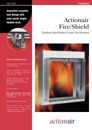
<strong>Flame</strong><strong>Shield</strong><br />
Introduction<br />
<strong>Flame</strong><strong>Shield</strong> <strong>Grease</strong> <strong>Filter</strong> <strong>Cells</strong><br />
Statistics indicate the large percentage of<br />
fires that occur in hotels, restaurants and<br />
similar locations actually start in the<br />
ventilating hood systems located adjacent<br />
to the cooking equipment.<br />
Here we have all the ingredients for a<br />
potential fire – a heat source, flammable<br />
grease and moving air. Many fires are<br />
probably ‘triggered’ by the grease filtering<br />
equipment itself, and not necessarily dirty<br />
filters either, though this would more often<br />
be the case. Substantial quantities of<br />
grease can be accumulated within<br />
conventional corrugated metal mesh<br />
filters in a matter of hours and since these<br />
have a very low resistance, have little or<br />
no tendency towards ‘holding back’ a<br />
flame. As a result, when fire ‘flare-up’<br />
occurs with a piece of cooking<br />
equipment, the flame from the ‘flare-up’ is<br />
immediately pulled through the<br />
conventional filter and ignites the<br />
accumulated grease in the filter and we<br />
have the heat source established for a<br />
grease duct fire.<br />
<strong>Flame</strong><strong>Shield</strong> grease filters reduce this fire<br />
hazard with their unique design concept<br />
of non grease loading and strategic<br />
arrangement of overlap baffles to restrict<br />
the passage of flame into the ductwork.<br />
They should be included in any newly<br />
designed hoods and incorporated in<br />
remodelled hoods. <strong>Flame</strong><strong>Shield</strong> grease<br />
filters play an important role in the overall<br />
effectiveness, hygiene and safety of the<br />
entire restaurant exhaust system.<br />
Since their introduction into Europe in<br />
1974 there has never been a hood or<br />
duct fire reported where <strong>Flame</strong><strong>Shield</strong><br />
grease filters are used.<br />
Perhaps no area of product design has<br />
suffered more from inattention over the<br />
years than the non-mechanical,<br />
apparently simple grease filter for use in<br />
restaurant exhaust hoods. The demands<br />
on a grease filter are straightforward. It<br />
should take the grease-laden air that rises<br />
from hot cooking fat, extract the grease<br />
particles, and pass the cleansed air into<br />
the exhaust system.<br />
The traditional corrugated metal mesh<br />
grease filters will do that to some degree<br />
of cleanliness and efficiency. It is the<br />
nature of these conventional filters to trap<br />
the grease within the metal mesh. The<br />
longer in use, the more grease is trapped,<br />
and the less efficient they become. They<br />
must be thoroughly cleaned to regain<br />
efficiency. The unique design concept of<br />
the <strong>Flame</strong><strong>Shield</strong> grease filter overcomes<br />
these drawbacks plus having other<br />
important advantages. The basic principle<br />
begins, of course, with extraction of the<br />
grease; with the use of coated baffles, the<br />
extracted grease flows away into a<br />
trough, and to a removable grease<br />
collector.<br />
The effluent from cooking processes<br />
consists of aerosols of water vapour<br />
mixed with evaporated fat or oil. These<br />
are carried from the cooking surface by<br />
the moving air being drawn into the<br />
exhaust hood. Although each aerosol is<br />
small, it is much heavier than the air<br />
molecules surrounding it. Thus, when the<br />
air stream containing these aerosols<br />
strikes the blank wall created by the<br />
<strong>Flame</strong><strong>Shield</strong> baffle system, the inertial<br />
force of the moisture-grease aerosol is<br />
considerably greater than that of the air<br />
molecule. While the air molecule changes<br />
direction easily, as shown in the diagram<br />
opposite, the aerosol strikes the baffle<br />
with considerable force, causing it to<br />
‘splatter’ on the surface. Because this<br />
surface is coated, the grease slides down<br />
the baffle to the trough and thence to the<br />
collecting container. Whereas, the<br />
heaviest aerosols, because of their<br />
greater inertial force, impinge on the<br />
surfaces of the baffles facing and<br />
perpendicular to the air flow, the lighter<br />
ones remain in the air stream. As the air<br />
stream is drawn through the baffle<br />
system, as shown in the diagram above,<br />
the restrictions in area created by the<br />
baffles causes the air to increase in<br />
velocity while<br />
Adjusting<br />
Screw<br />
<strong>Grease</strong><br />
Laden<br />
Air<br />
<strong>Coated</strong><br />
<strong>Baffle</strong>s<br />
changing direction by 180°. Since the<br />
inertial force is a product of mass and the<br />
square of the velocity, this increase in<br />
velocity serves to increase the inertial<br />
force of the remaining smaller aerosols,<br />
causing them to impinge on the inner<br />
surfaces of the baffles in the same<br />
manner as the heavier aerosols impinged<br />
on the entering surfaces.<br />
The design of the baffle system allows<br />
several impingement surfaces and two<br />
rapid 180° direction changes. Because<br />
<strong>Flame</strong><strong>Shield</strong> grease filters remove grease<br />
aerosols from the air stream and drain it<br />
away instead of retaining it, there is no<br />
build-up of grease in the path of the air.<br />
<strong>Flame</strong><strong>Shield</strong> grease filters therefore,<br />
ensure a constancy of air flow never<br />
before achievable with conventional metal<br />
mesh-type filters.<br />
2 www.actionair.co.uk
<strong>Flame</strong><strong>Shield</strong><br />
Adjustability<br />
<strong>Flame</strong><strong>Shield</strong> grease filters have a unique<br />
feature: adjustable baffles that allow air<br />
system balancing regardless of where the<br />
filters are located relative to the exhaust<br />
fan. This will enable designers and<br />
operators to actually balance the<br />
ventilation required over various types of<br />
cooking equipment after the entire<br />
installation has been completed, allowing<br />
more exhaust where more is required,<br />
and less where less is required, to meet<br />
varying cooking conditions, and even<br />
more important, retaining the unbalanced<br />
condition once the <strong>Flame</strong><strong>Shield</strong> filters<br />
have been adjusted to create it.<br />
Application<br />
Parameters<br />
The key criterion determining ventilation<br />
requirements in most commercial kitchens<br />
and restaurants is the exhaust rate<br />
needed to provide ‘capture velocity’ for<br />
the various appliances. This refers to the<br />
air velocity required at a given point near<br />
the cooking surface that is required to<br />
entrain heat, vapour, mist, grease or<br />
smoke and odours in the ventilation air<br />
stream. Entrainment occurs as air flows<br />
near the appliance and exhausts through<br />
the hood. The following illustrates how<br />
velocities in the capture zone are<br />
necessarily lower than at the hood face<br />
and in practice it has been proven that a<br />
velocity of 0.152m/s along the edge of<br />
the cooking equipment would develop<br />
adequate capture.<br />
The velocities, as shown on the following<br />
table, will ensure efficient removal of<br />
cooking contaminants.<br />
Number of<br />
Exposed Sides<br />
Air Velocity Across<br />
Area of Hood<br />
4 canopy-island 0.761m/s<br />
3 canopy-wall 0.507m/s<br />
2 canopy-corner 0.507m/s<br />
wall<br />
1 canopy-apron 0.507m/s<br />
protected<br />
It is essential to place hoods above all<br />
roasting, grilling, frying, steaming and<br />
vapour producing appliances, and good<br />
practice to supply hoods for tea making<br />
equipment and boilers, to localise the<br />
escape of cooking odours and convected<br />
heat, and also to protect decor.<br />
The dimensions of the base of the hood<br />
should be larger than the cooking surface<br />
it covers to adequately remove the<br />
contaminants generated in the cooking<br />
process. A general rule that has proved<br />
very satisfactory is summarised as<br />
follows: The length and width of the hood<br />
base should equal the overall dimension<br />
of the appliances it covers plus 300mm<br />
minimum overhang on each side of the<br />
equipment that is not enclosed by an<br />
apron or adjacent wall. The distance from<br />
the base of the hood to the cooking<br />
surface will normally be 900mm to<br />
1200mm since the kitchen employees<br />
must work underneath the hood.<br />
Excessive clearance between the cooking<br />
surface and hood hampers the<br />
effectiveness of the exhaust system and<br />
should be avoided.<br />
The hood itself must be deep enough to<br />
permit the installation of grease filters at a<br />
minimum 45° angle from the horizontal.<br />
The minimum height from the cooking<br />
surface to the lower edge of the grease<br />
filter should not be less than:<br />
a. No exposed flames – grills, french<br />
fryers, etc. – 750mm.<br />
b. Exposed charcoal and charcoal<br />
type fires – 1350mm.<br />
c. Exposed fires other than b. – 1100mm.<br />
0.457m/s<br />
HOOD FACE<br />
0.507/0.761m/s<br />
0.355m/s<br />
STREAMLINES<br />
0.254m/s<br />
CAPTURE ZONE<br />
APPLIANCE<br />
VELOCITY<br />
CONTOURS<br />
0.152m/s<br />
www.actionair.co.uk 3
<strong>Flame</strong><strong>Shield</strong><br />
Selection<br />
Standard Sizes<br />
1.The information provided here will<br />
enable the designer to select, apply and<br />
efficiently use <strong>Flame</strong><strong>Shield</strong> grease filters.<br />
For optimum performance we<br />
recommend that selections and<br />
adjustments are only made from the<br />
shaded portions of the graphs.<br />
50 -<br />
100mm<br />
STATIC PRESSURE<br />
POINT<br />
EXTRACTOR UNIT<br />
Nominal Size (mm)<br />
Actual Size (mm)<br />
Width x Height x Depth Width x Height x Depth<br />
508 x 254 x 50 495 x 241 x 48<br />
508 x 406 x 50 495 x 394 x 48<br />
508 x 508 x 50 495 x 495 x 48<br />
2. All static pressures indicated are<br />
measured 150mm approximately behind<br />
the <strong>Flame</strong><strong>Shield</strong> filters and with the baffles<br />
in a fully open position.<br />
3. The static pressure loss of conventional<br />
metal mesh grease filters should be<br />
based on their operational resistance<br />
under maximum recommended grease<br />
loading conditions; usually, at<br />
least, twice the initial resistance. Whereas,<br />
<strong>Flame</strong><strong>Shield</strong> filters, with their unique<br />
design concept of non grease loading<br />
and constancy of airflow characteristics,<br />
the initial resistance is also the operational<br />
resistance.<br />
AIR FLOW<br />
VELOCITY<br />
POINT<br />
150mm<br />
Regenerated Sound Power Level (dBW)<br />
Free Area (Inside Frame)<br />
Nominal<br />
508 x 254 441 x 187 3.3<br />
508 x 406 441 x 340 4.5<br />
508 x 508 441 x 441 5.3<br />
Weight (Kg)<br />
Cell Only<br />
Unit Size Static Pressure Frequency Hz<br />
in mm in Pa 125 250 500 1k 2k 4k<br />
508 x 254 50 45.5 46.0 43.0 42.0 40.5 22.0<br />
508 x 254 100 52.5 53.5 52.5 52.5 52.0 36.5<br />
508 x 406 50 45.5 46.5 44.5 44.0 43.5 27.0<br />
508 x 406 110 51.0 52.5 52.0 52.0 52.5 39.0<br />
508 x 508 50 45.5 46.5 45.5 44.0 43.5 26.5<br />
508 x 508 120 52.5 55.0 54.5 53.0 54.0 50.5<br />
Single Cell Air Capacity Data (<strong>Baffle</strong>s Fully Open)<br />
150<br />
508mm x 254mm 508mm x 406mm 508mm x 508mm<br />
125<br />
STATIC PRESSURE Pa<br />
100<br />
75<br />
50<br />
25<br />
NOTE 1 Pa = 1 N/m 2<br />
0<br />
0.15 0.20 0.25 0.30 0.35 0.40 0.45 0.50 0.60<br />
Air Volume m 3 /s<br />
4 www.actionair.co.uk
<strong>Flame</strong><strong>Shield</strong><br />
Performance Comparison<br />
These photographs illustrate the<br />
difference between <strong>Flame</strong><strong>Shield</strong> <strong>Grease</strong><br />
<strong>Filter</strong>s and conventional mesh filters<br />
under fire conditions.<br />
Here the fire has reached a maximum<br />
intensity of 1093°C.<br />
<strong>Flame</strong><strong>Shield</strong> is intact while the<br />
conventional filter has burned through.<br />
The fire has been tempered to show the<br />
gaping hole in the conventional filter<br />
which has allowed flame to race through<br />
the hole and three metres into the<br />
duct system.<br />
<strong>Flame</strong><strong>Shield</strong> confines fires to the cooking<br />
area. The photographs were taken using<br />
conventional metal mesh grease filters<br />
and <strong>Flame</strong><strong>Shield</strong> <strong>Grease</strong> <strong>Filter</strong>s side by<br />
side.<br />
Prior to the fire, 1.35Kg of cooking oil<br />
was evaporated through the system so<br />
that any grease accumulations on the<br />
conventional and <strong>Flame</strong><strong>Shield</strong> grease<br />
filters would be typical of a normal<br />
installation. The metal mesh filter<br />
collected grease particles, creating a<br />
dangerous fuel cell, which is easily ignited<br />
and can expand small cooking flare ups<br />
into catastrophes. The <strong>Flame</strong><strong>Shield</strong> <strong>Filter</strong><br />
extracted the grease which ran-off to a<br />
container.<br />
The fire was produced by 0.5 litre of oil<br />
poured into a shallow pan on a gas fired<br />
cooking appliance.<br />
In the first picture, the fire has reached<br />
maximum intensity of 1093°C and the hot<br />
spot in the conventional metal mesh filter<br />
is very apparent with the <strong>Flame</strong><strong>Shield</strong> not<br />
being affected. In the second picture, a<br />
steel plate has been placed over the<br />
shallow pan containing the burning oil, so<br />
as to reduce the flames. A large hole has<br />
burned through the conventional filter and<br />
the <strong>Flame</strong><strong>Shield</strong> filter is still not affected.<br />
The flames burning through the metal<br />
mesh filter caused a shower of molten<br />
metal to fall into the cooking appliance<br />
and area below. The flames then raced<br />
through the hole and upward into the<br />
duct system above the metal mesh filter<br />
for a distance of approximately 3 metres<br />
and observers also noted sparks being<br />
projected into the duct by the filter; no<br />
sparks were noted coming from the<br />
<strong>Flame</strong><strong>Shield</strong> filter.<br />
Mesh <strong>Filter</strong><br />
<strong>Flame</strong><strong>Shield</strong><br />
Mesh <strong>Filter</strong><br />
<strong>Flame</strong><strong>Shield</strong><br />
www.actionair.co.uk 5
<strong>Flame</strong><strong>Shield</strong><br />
Specification<br />
<strong>Flame</strong><strong>Shield</strong> adjustable coated baffle<br />
grease and casing assemblies shall be<br />
fixed where indicated and to the<br />
requirements of the relevant fire<br />
regulations the <strong>Flame</strong><strong>Shield</strong> grease filters<br />
shall have non grease loading and<br />
constancy of air flow characteristics and<br />
with a strategic arrangement of adjustable<br />
overlap baffles to restrict the passage of<br />
flame into ductwork.<br />
Each filter shall comprise of a telescoping<br />
outside front and rear frame, containing<br />
weep holes for grease drainage, and<br />
welded to a protective face of expanded<br />
metal, all manufactured from nickel plated<br />
mild steel.<br />
Two opposing baffle assemblies<br />
manufactured from Electroplated Zinc<br />
Steel and coated shall be mounted within<br />
the frames, reversed one to the other in<br />
staggered alignment and separated by<br />
four adjusting screws and springs holding<br />
the unit together to permit air flow<br />
regulation.<br />
A pair of handles shall be provided on<br />
each filter cell for ease of removal and<br />
replacement.<br />
The <strong>Flame</strong><strong>Shield</strong> grease filter cells shall be<br />
as supplied by ACTIONAIR.<br />
Cleaning: <strong>Flame</strong><strong>Shield</strong> grease filter<br />
cells should be cleaned on a regular<br />
cycle basis relevant to site conditions,<br />
in a solution of hot water and<br />
household detergent – Caustic<br />
Soda based solutions and/or<br />
Abrasives should never be used.<br />
6 www.actionair.co.uk
<strong>Flame</strong><strong>Shield</strong><br />
Ordering Information<br />
Example<br />
Quantity Series Duty m 3 /s / Cell Size (mm)<br />
4 <strong>Flame</strong><strong>Shield</strong> 0.35 508(W) x 508(H) x (D)50<br />
Number of units<br />
required<br />
<strong>Flame</strong><strong>Shield</strong> Air Volume m 3 /s<br />
508 x 254 x 50<br />
508 x 406 x 50<br />
508 x 508 x 50<br />
www.actionair.co.uk 7
<strong>Flame</strong><strong>Shield</strong><br />
Ruskin Air Management Limited<br />
is a ISO 9001 and 14001 registered<br />
company.<br />
The statements made in this brochure or by our<br />
representatives in consequence of any enquiries<br />
arising out of this document are given for information<br />
purposes only. They are not intended to have any<br />
legal effect and the company is not to be regarded<br />
as bound thereby. The company will only accept<br />
obligations which are expressly negotiated for and<br />
agreed and incorporated into a written agreement<br />
made with its customers.<br />
Due to a policy of continuous product development<br />
the specification and details contained herein are<br />
subject to alteration without prior notice.<br />
Comprehensive and detailed information<br />
is available for all <strong>Actionair</strong> products.<br />
Visit our website at www.actionair.co.uk<br />
Ruskin Air Management Limited<br />
South Street, Whitstable, Kent<br />
CT5 3DU England.<br />
Tel: 01227 276100<br />
Fax: 01227 264262<br />
Email: sales@actionair.co.uk<br />
Website: www.actionair.co.uk<br />
LNNN00121