scanCONTROL 2700 - Micro-Epsilon
scanCONTROL 2700 - Micro-Epsilon
scanCONTROL 2700 - Micro-Epsilon

You also want an ePaper? Increase the reach of your titles
YUMPU automatically turns print PDFs into web optimized ePapers that Google loves.
5.<br />
Laser Safety<br />
The <strong>scanCONTROL</strong> 2800/2810 sensors operate with a semiconductor laser having a<br />
wavelength of 658 nm (visible/red). The laser operation is indicated visually by the LED on<br />
the sensor and on the controller.<br />
Laser Class 2M<br />
<strong>scanCONTROL</strong> 2800/2810 sensors with a maximum laser power up to 15 mW are classified<br />
in Laser Class 2M (IIM). The following information labels are fitted to the sensor<br />
housing (front and rear side). If both information labels are hidden in the installed state,<br />
the user must ensure that additional labels are fitted at the point of installation.<br />
Laser radiation<br />
Do not stare into the beam or view<br />
directly with optical instruments<br />
Class 2M Laser Product<br />
IEC 60825-1:2008-05<br />
P≤15 mW; E≤7.5 mW/cm²; =658 nm<br />
Hazard to the eye via laser radiation! Consciously close your eyes<br />
or turn away if the laser radiation impinges on the eye.<br />
Lasers of Class 2M are not subject to notification and a laser protection officer is not required.<br />
Mark the laser area recognizable and everlasting.<br />
Laser Class 3B<br />
<strong>scanCONTROL</strong> 2800/2810 sensors with a maximum laser power up to 50 mW are classified<br />
in Laser Class 3B (IIIB).<br />
Injury to the eye or the skin via laser radiation! Consciously close<br />
your eyes or turn away if the laser radiation impinges on the eye or<br />
the skin.<br />
Class 3B (IIIB) laser sensors are notifiable and a laser protection officer is required either.<br />
During operation the laser area has to be restricted and marked. The following information<br />
label should be fitted to the sensor housing (front and rear side):<br />
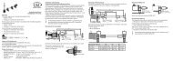
Beam attenuator<br />
Laser radiation<br />
Avoid exposure to the beam<br />
Class 3B Laser Product<br />
IEC 60825-1:2008-05<br />
P≤50 mW; =658 nm<br />
The beam attenuator prevents access to all<br />
laser and collateral radiation. The figures show<br />
the sensor with closed and open beam attenuator.<br />
The beam attenuator must be open during<br />
measurement.<br />
Sensors need an external key switch<br />
to switch off the laser to be classified<br />
in Laser Class 3B (IIIB).<br />
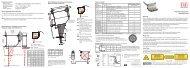
6.<br />
Connections, LED Displays<br />
Laser ON/OFF Reset button Sensor Video output<br />
LED Displays<br />
Power Mode button Analog output<br />
Connections<br />
to PC<br />
Serial<br />
interfaces<br />
Switch, synchron and<br />
trigger signal, Laser ON/OFF<br />
„Power on“ No power supply Power supply is on<br />
„Laser on“ Laser is off Laser is on<br />
„Error“<br />
„Control“<br />
„Mode 1“<br />
„Mode 2“<br />
Errors are encoded by different flashing sequences, see Chap. 13.3 instruction<br />
manual<br />
No communication<br />
with PC<br />
flashes long during data transmission<br />
flashes short during control access<br />
Operation mode<br />
Default Mode 1 Mode 2 Mode 3<br />
A green LED on the sensor signals “laser on”.<br />
Power supply<br />
Pin Assignment PC2800-x<br />
Analog output (2 x koaxial)<br />
Pin Assignment C2800-x<br />
1 +24 VDC red 1 2 Analog 1 (z) white<br />
black or<br />
2 GND<br />
2 3 GND 1 screen<br />
blue<br />
Housing Screen black 4 Analog 2 (x) brown<br />
View: Solder-pin side, male cable connector 1 GND 2 screen<br />
The minus pole of the supply voltage (Power<br />
GND) is electrically isolated from the system<br />
ground.<br />
i<br />
50 Ohm output impedance,<br />
5 mA output current max.,<br />
not short-circuit-proof<br />
The Laser ON/OFF<br />
switch disconnects<br />
the power to the<br />
laser sensor for<br />
maintenance purposes.<br />
If the switch is<br />
in position „Off“, the<br />
associated green<br />
LED is off and the<br />
sensor connector<br />
may be disconnected.<br />
1<br />
4<br />
2 3<br />
Solder-pin<br />
side, male<br />
cable connector<br />
The sensor may only be plugged/unplugged with power switched off, i.e. with theoperating<br />
voltage switched off or with the keyswitch in the “Off” position (Laser off).<br />
Switch-, Synchron- and Trigger Signal, Laser ON/OFF<br />
Pin Assignment Function, Remark<br />
1 Sync. In +<br />
7 Sync. In -<br />
11 Sync. Out<br />
Optocouppler<br />
11 15<br />
6 10<br />
1 5<br />
6 GND Sync. Out System ground 15-pole HD subminiature connector,<br />
13 Laser On/Off + solder pin side male cable connector<br />
Optocouppler<br />
3 Laser On/Off - The connections 2, 3, 4, 5 and 9 are<br />
electrically connected to the minus<br />
8 Input +<br />
Mode, optocouppler pole (Power-GND) of the 24 V DC<br />
2 Input -<br />
supply voltage.<br />
15 Output +<br />
5 Output -<br />
10 Output +<br />
4 Output -<br />
14 Output +<br />
9 Output -<br />
12 --- n.c.<br />
Mode 1, opto decoupled<br />
Mode 2, opto decoupled<br />
Error, opto decoupled<br />
Open collector outputs, short circuit<br />
and reverse-polarity protected up to<br />
30 VDC,<br />
The resistance in the conducting state<br />
is 15 Ohm or less at I L<br />
= 100 mA.<br />
External circuit with load (e.g. relay) between external auxiliary power (e.g. power supply<br />
+ 24 V DC) and the output+. Connect the negative pole of the auxiliary power with the<br />
negative pole of the power supply (does not apply with use of the power supply).<br />
Using the <strong>scanCONTROL</strong> 2810 sensor the pin assignment changes as follows:<br />
15 Output + Digital output 1,<br />
5 Output - opto decoupled<br />
10 Output + Digital output 2,<br />
4 Output - opto decoupled<br />
14 Output + Digital output 3,<br />
9 Output - opto decoupled<br />
Output Circuit of the Error and Mode Outputs<br />
Controller<br />
T<br />
Output<br />
Periphery<br />
max. 30 VDC<br />
+ +<br />
I max. 100 mA<br />
L<br />
0 V GND<br />
R<br />
L<br />
1...10<br />
kOhm<br />
Open collector outputs, short circuit<br />
and reverse-polarity protected up to<br />
30 VDC,<br />
The resistance in the conducting<br />
state is 15 Ohm or less at<br />
I L<br />
= 100 mA.<br />
Mode<br />
Factory<br />
setting<br />
States on the error output: T is closed, if an error occurs.<br />
Output<br />
Mode1<br />
T closed<br />
Output<br />
Mode 2<br />
T closed<br />
1 T open T closed<br />
2 T closed T open<br />
3 T open T open<br />
Synchronization and Triggering<br />
3.3 V Controller Periphery<br />
33 Ohm Sync-out<br />
Synchronization output circuit<br />
Case<br />
Periphery<br />
Controller<br />
R 1<br />
I = 10...15 mA<br />
V 1<br />
100 Ohm<br />
U F<br />
=<br />
appr.<br />
7<br />
1 V<br />
Synchronization input circuit<br />
The optocoupler at the sync input needs a current of 10 to 15 mA for operation. Do not<br />
exceed this current value with external trigger sources.<br />
1) Resistor Rv is used in combination with a trigger input only, see Chap. 6.5 instruction manual.<br />
Laser ON/OFF, Mode and Encoder Inputs<br />
The two available digital inputs with the same input circuit are configured in the standard<br />
version as “laser on/off” and “mode” inputs. They can be directly controlled by open<br />
collector transistor inputs or relay contacts. The power supply + 24 V DC is internally<br />
connected as an auxiliary power supply.<br />
i<br />
Laser Class 2M/IIM (15 mW): Laser is on, without connection between the pins 13<br />
and 3 also.<br />
Laser Class 3B/IIIB (50 mW): Laser is on, if Pin 13 and 3 are connected.<br />
HTL<br />
8 (13)<br />
2 (3)<br />
Encoder<br />
Periphery<br />
2 (3)<br />
Relay<br />
8 (13)<br />
8 (13)<br />
2 (3)<br />
Open-<br />
Collector<br />
Controller<br />
I ca. 7 mA<br />
3.3 kOhm<br />
Input circuit of the laser ON/OFF and mode inputs.<br />
+24 VDC<br />
The mode input reacts<br />
like the identically named<br />
button and switches<br />
cyclically between the<br />
various user modes.<br />
Pin 8 and pin 2 are the<br />
mode or encoder inputs.
laser off<br />
on<br />
24VDC<br />
reset<br />
mode<br />
power on<br />
laser on<br />
error<br />
control<br />
sensor<br />
1394 1394 1394 RS 232 RS 422<br />
analog<br />
video<br />
synchron<br />
laser off<br />
on<br />
24VDC<br />
reset<br />
mode<br />
power on<br />
laser on<br />
error<br />
control<br />
sensor<br />
1394 1394 1394 RS 232 RS 422<br />
analog<br />
video<br />
synchron<br />
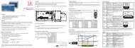
FireWire Connection (1394), Standard connection to PC<br />
FireWire (or the IEEE 1394 bus) is a serial bus system which can be branched as required<br />
with up to 63 devices operating together on one PC interface. The data are transmitted in<br />
both directions (bi-directional) on symmetrical and shielded two wire lines via standard<br />
cable.<br />
Restrictions:<br />
-- The branching must not include loops.<br />
-- A maximum of 17 devices can be cascaded in a line (“daisy-chained”).<br />
-- The maximum cable length between two devices is 4.5 m.<br />
-- The maximum length of a “daisy chain” section is 72 m.<br />
-- The data rate of 400 Mbit/s applies to the whole bus and must be shared between the<br />
connected devices. In the standard configuration up to four <strong>scanCONTROL</strong> 2800/2810<br />
controllers can be operated on one bus.<br />
PC with PCI<br />
interface card Controller 1 Controller 2<br />
Matrox Meteor II<br />
IEEE 1394<br />
mode 2<br />
mode 1 3<br />
IEEE 1394 IEEE 1394<br />
Camera 1<br />
Example of a FireWire configuration<br />
6-pole connector Connector type „1394“<br />
Pin<br />
Signal<br />
1 NC<br />
2 NC<br />
3 TPB-<br />
4 TPB+<br />
5 TPA-<br />
6 TPA+<br />
5<br />
6<br />
3<br />
4<br />
1<br />
2<br />
View on solder pin side<br />
mode 2<br />
mode 1 3<br />
IEEE 1394 / Controller 3<br />
The PIN numbers refer to the <strong>scanCONTROL</strong> 2800/2810.<br />
<strong>Micro</strong>-<strong>Epsilon</strong> recommends to use the SCD-IEEE-1394-3<br />
FireWire cable from the optional accessories.<br />
Three fully equivalent 6-pole connection sockets are provided<br />
with connection assignment according to the 1394-1995<br />
specification. The controller does not supply any operating<br />
voltage to the 1394 connection sockets. The IEEE 1394<br />
(FireWire) interfaces are electrically isolated from the rest of<br />
the circuit.<br />
7. System Requirements <strong>scanCONTROL</strong> Software<br />
-- Windows XP SP 2 (32) / Windows Vista (32) / Windows 7 (32/64)<br />
-- Pentium III 800 MHz / 512 MB RAM<br />
-- Screen resolution: 1024 x 76<br />
8.<br />
Quick Start: Commissioning, Software<br />
Install the software.<br />
i<br />
9.<br />
Please insert the <strong>scanCONTROL</strong><br />
Demo CD in the CD-ROM device.<br />
Follow the dialog through the installation<br />
process.<br />
A. Reading of installation help<br />
B. Installation of software<br />
C. Further informations in the online<br />
documentation<br />
The sensor may only be connected<br />
to the controller with<br />
power switched off or with the<br />
keyswitch in the “Off” position<br />
(Laser off).<br />
Mount the sensor according to the installation instructions.<br />
Connect the sensor to the controller. Connect the controller to the PC using a FireWire<br />
cable.<br />
Connect the controller to display or monitoring units.<br />
Connect the controller to the power supply.<br />
Connect the shield of the power supply cable to the PE protective earth conductor<br />
of the main power supply. Close plug-in connections not needed with the supplied<br />
protective caps for ODU sockets. Switch on the 24 VDC power supply.<br />
Sensor and controller need a warm-up time of typically 20 minutes for high precision<br />
measurements.<br />
Install the drivers for the measuring system according to the instructions on the<br />
supplied CD-ROM ([CD]:\\Documentation\english\Installation\index.html).<br />
Driver Installation for Windows XP<br />
Finish the installation of the Configuration Tools software completely. This procedure<br />
is described in section 8. Connect the controller to the PC using the 1394 FireWire<br />
cable. Switch on the power supply.<br />
If the installation doesn’t start automatically, search for <strong>scanCONTROL</strong> in the device manager<br />
(Start > Control Panel > System > Device Manager). <strong>scanCONTROL</strong> is classified as<br />
camera device and is either located under “Imaging Devices” or “Other Devices”. Rightclick<br />
the camera device and choose “Update Driver”.<br />
The ”Hardware Update Wizard” will appear.<br />
Mark “No, not this time” and click on “Next”.<br />
Click on ”Next” to confirm this dialog.<br />
Now the operating system installs the driver for <strong>scanCONTROL</strong>. The ”Hardware installation”<br />
dialog will appear.<br />
Click on ”Continue anyway” to confirm this dialog.<br />
Click on “Finish” to end the driver installation.<br />
If you want to install the driver at a later date or in case of an incorrect installation of the<br />
driver, you have to install the driver manually.<br />
i<br />
10.<br />
First Profile<br />
Now start the <strong>scanCONTROL</strong> Configuration Tools software. Click on “Display Profiles“<br />
in the main window.<br />
If the software shows the error message “No <strong>scanCONTROL</strong> found” in the status line,<br />
please check the installed driver in the device manager (Start > Control Panel > System<br />
> Device Manager).<br />
11.<br />
How to Access Profile Data<br />
Profile data of <strong>scanCONTROL</strong> can be accessed via:<br />
*X9771109-A04*<br />
www.micro-epsilon.de<br />
MICRO-EPSILON Messtechnik GmbH & Co. KG<br />
Königbacher Str. 15<br />
94496 Ortenburg, Germany, Tel. +49 (0) 85 42/1 68-0<br />
On the left side you can adjust<br />
the settings for your measurement<br />
task, the right side shows<br />
the profile data and information<br />
about the measurement.<br />
-- DCAM standard v.1.30 for digital cameras via IEEE 1394 FireWire interface<br />
-- SDK for fast application integration (C, C++ and others)<br />
For details refer to the enclosed online manuals.<br />
12.<br />
Please refer to<br />
Further Information<br />
-- the enclosed online manual<br />
-- the section „Status and Error Messages“ and „Notes“ in the <strong>scanCONTROL</strong> Configuration<br />
Tools manual.<br />
You will find details to the separate programs in the respective instruction manuals or in<br />
the instruction manual of this sensor, Chap. 6.2. You will find the instruction manuals online<br />
or on the provided CD.<br />
X9771109-A041082MSC<br />
1.<br />
Warnings<br />
Assembly Instructions<br />
<strong>scanCONTROL</strong> 2800/2810<br />
Connect the power supply and the display-/output device in accordance with the safety regulations<br />
for electrical equipment. The power supply may not exceed the specified limits.<br />
>> Danger of injury, damage or destruction of the sensor/controller<br />
Avoid shock and vibration to the sensor/controller. Avoid continous exposure to dust and<br />
spray on the sensor/controller. Avoid exposure to aggressive materials (washing agent,<br />
penetrating liquids or similar) on the sensor.<br />
>> Damage to or destruction of the sensor/controller<br />
Read the detailed instruction manual before operation of the sensor. You will find this<br />
online or on the provided CD.<br />
2.<br />
Notes on CE Identification<br />
The following applies to the <strong>scanCONTROL</strong> 2800/2810: EU Regulation 2004/108/EG<br />
The sensor fulfills the specifications according to the following standards:<br />
-- DIN EN 55011/ 11.2007 / Industrial scientific and medical (ISM) equipment / Electromagnetic<br />
disturbance characteristics<br />
-- DIN EN 61 000-6-2/ 03.2006 / Electromagnetic Compatibility (EMC) / Immunity to interference<br />
/ industrial area<br />
-- DIN EN 61326/ 10.2006 / Electrical equipment<br />
The sensor fulfills the specifications of the EMC requirements, if the instructions in the<br />
manual are followed.<br />
3. Proper Environment<br />
-- Protection class: IP 65 (with connected sensor cable)<br />
-- Operating temperature: 0 to +50 °C (+32 to +122 °F), by free circulation of air<br />
-- Storage temperature: -20 to +70 °C ( -4 to +158 °F)<br />
-- Humidity:<br />
5 - 95 % (non condensing)<br />
-- Vibration:<br />
DIN EN 60068-2-6 (sine shaped)<br />
-- Mechanical shock: DIN EN 60068-2-29<br />
4. Standard Equipment <strong>scanCONTROL</strong> 2800/2810<br />
-- 1 Sensor LLT2800/2810 and controller<br />
-- 1 Power supply cable PC2800-3; round connector and free cable ends<br />
-- 1 Analog output plug, 4-pole, (ODU, Series MiniSnap L, Order no. S11L0C - T04MJGO<br />
- 7200)<br />
-- 1 <strong>scanCONTROL</strong> Demo-CD with drivers, programs and documentation<br />
-- 1 Sensor inspection log / Assembly instructions<br />
-- 1 FireWire connecting cable, 3 m long.