Assembly instructions induSENSOR VIP series (PDF ... - Micro-Epsilon
Assembly instructions induSENSOR VIP series (PDF ... - Micro-Epsilon
Assembly instructions induSENSOR VIP series (PDF ... - Micro-Epsilon

Create successful ePaper yourself
Turn your PDF publications into a flip-book with our unique Google optimized e-Paper software.
<strong>Assembly</strong> Instructions<br />
<strong>induSENSOR</strong>, <strong>VIP</strong> <strong>series</strong><br />
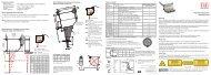
Warnings<br />
The power supply may not exceed the specified limits.<br />
> > Danger of injury<br />
> > Damage to or destruction of the sensor<br />
Power supply must be connected in accordance with the safety regulations<br />
for electrical equipment.<br />
> > Danger of injury<br />
> > Damage to or destruction of the sensor<br />
Avoid shocking and knocking the sensor<br />
> > Damage to or destruction of the sensor<br />
> > Avoid bending the sensor rod.<br />
> > Damage to or destruction of the sensor<br />
Sensor<br />
housing<br />
Sensor rod<br />
Notes on CE Identification<br />
The following applies for the <strong>induSENSOR</strong>, <strong>VIP</strong> <strong>series</strong>:<br />
EC regulation 2004/108/EC<br />
The <strong>induSENSOR</strong>, <strong>VIP</strong> <strong>series</strong>, satisfies the requirements of the standards EN<br />
61326-1: 2006-10 and DIN 61326-2-3: 2007-05.<br />
Proper Environment<br />
--<br />
Protection class for sensor: IP 67 (only with plug connected)<br />
--<br />
Operating temperature: -40 up to +85 °C (RL ≤ 500 Ohm) -40 to +185 °F<br />
--<br />
Storage temperature: -40 up to +100 °C (-40 up to +212 °F)<br />
--<br />
Humidity: 5 - 95 % (non condensing)<br />
--<br />
Ambient pressure: Atmospheric pressure<br />
--<br />
EMC acc. to: EN 61326-1: 2006-10 and DIN 61326-2-3: 2007-05<br />
Installation and Mounting<br />
Centering and Mounting the Measuring Ring<br />
Install the measuring ring in an electrically non-conductive mounting facility<br />
( e.g. plastics). The dimensions of the measuring ring are shown in the<br />
following figures. MICRO-EPSILON recommends to use the mounting kit<br />
MBS 12/8, which is available as an accessory, see Chap. 8.1 of the instruction<br />
manual and Figure “Sensor mounting with mounting kit MBS 12/8”.<br />
Please observe the position of the measuring ring at the zero point (= 4 mA<br />
output), see also the following figures.<br />
A slightly eccentrical mounting of the measuring ring has no negative influence<br />
on the sensor signal. The measuring ring is attached on the target to<br />
be measured by means of circumferential clamping or gluing.<br />
i<br />
An electrically conductive mounting material (e.g. measuring ring<br />
mounting facility) influences the measuring result. The specified<br />
technical data are no longer observed!<br />
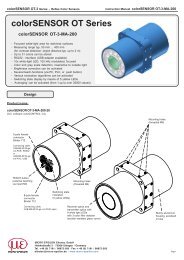
Mounting of the Housing GA<br />
Plug<br />
7-contact<br />
48<br />
(1.89)<br />
Wrench<br />
size 32<br />
13.8<br />
(.54) 40<br />
(1.57)<br />
B<br />
12<br />
(.47)<br />
M18x1.5<br />
C<br />
A<br />
Measuring range<br />
ø12x1<br />
(dia. .47<br />
x 0.4)<br />
Start of measuring<br />
range, I OUT<br />
= 4 mA<br />
ø8<br />
(dia. .31)<br />
End of measuring<br />
range, I OUT<br />
= 20 mA<br />
Dimensional drawing housing GA, dimensions in mm (inches), not to scale<br />
The sensor is screwed to the mounting<br />
plate using the M18 thread, see Wrench size 32<br />
B<br />
figure on the right side.<br />
Mounting plate<br />
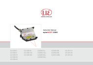
Mounting of the Housing ZA<br />
The sensor is fastened at both ends of the sensor rod (area B and D, see<br />
the lower figure) by means of a clamping / mounting facility.<br />
53 (2.09)<br />
Plug<br />
7-contact<br />
40<br />
(1.57)<br />
ø12<br />
(dia. .47)<br />
B<br />
ø30.5<br />
(dia. 1.20)<br />
12<br />
(.47)<br />
C<br />
A<br />
Measuring range<br />
ø12x1<br />
dia. .47 x<br />
.04)<br />
Start of measuring<br />
range, I OUT = 4 mA<br />
End of measuring<br />
range, I OUT<br />
= 20 mA<br />
ø8<br />
(dia..31)<br />
Dimensional drawing housing ZA, dimensions in mm (inches), not to scale<br />
Bending radius sensor cable:<br />
> 30 mm (once)<br />
> 90 mm (permanent)<br />
B<br />
Measuring range A B C D<br />
50 (1.97) 105 (4.13) 24 (.94) 11.5 (.45) 19.5 (.77)<br />
100 (3.94) 175 (6.89) 27 (1.06) 22 (.87) 26 (1.02)<br />
150 (5.91) 242 (9.53) 30 (1.18) 33 (1.30) 29 (1.14)<br />
D<br />
Mounting Kit MBS 12/8<br />
2x M4,<br />
length of thread<br />
(min.) 16 mm (.63 “)<br />
Sensor mounting with mounting kit MBS 12/8<br />
2x M4,<br />
length of thread<br />
(min.) 12 mm (.47 “)<br />
Precautionary Measure<br />
The measuring ring must not contact the sensor rod during operation.<br />
> > Damage to or destruction of the sensor through abrasion.<br />
Avoid bending or shortening the measuring ring.<br />
> > Loss of specified technical data<br />
The minimum bending radius is 30 mm (1.2 “) once, repeated: 90 mm<br />
(3.5 “) for the sensor cable C 703x.<br />
> > Damage to or destruction of the sensor cable<br />
i<br />
The specified technical data are valid only, if the measuring ring is<br />
used supplied from MICRO-EPSILON!
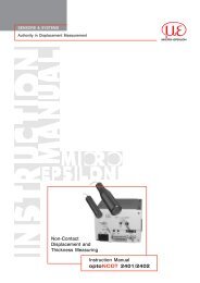
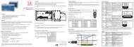
Measuring Principle<br />
Output signal (mA)<br />
20<br />
12<br />
4<br />
0<br />
1/2<br />
Measuring range<br />
Measuring ring<br />
1<br />
Sensor rod<br />
Power Supply and Display / Output Device<br />
Power supply and signal output are effected through the 7-contact connector<br />
at the sensor’s electronic housing. The pin assignment is shown in<br />
drawing and table stated below.<br />
6<br />
7<br />
5 4<br />
3<br />
1<br />
2<br />
View: Solder<br />
pin side,<br />
female cable<br />
connector<br />
U e<br />
Pin Assignment Color C703<br />
1 Supply + (18 ... 30 VDC) white<br />
2 0 V Ground brown<br />
3<br />
I OUT<br />
4 ... 20 mA<br />
(U OUT<br />
1 ... 5 V) 1 green<br />
4 Signal ground yellow<br />
5 SCL (sensor calibration) grey<br />
6 SDA (sensor calibration) pink<br />
7 not connected (n.c.) blue<br />
I a<br />
i<br />
Make sure, that the output noise of the power supply units does not<br />
exceed 5 mV ss<br />
, if the sensors are supplied through switched-mode<br />
power supply units,<br />
Pin 2 is connected with pin 4 on the sensor electronics. The screen of the<br />
C703 sensor cable is connected with the connector housing.<br />
Connect the screen of the C703 sensor cable with the protective earth<br />
conductor on power side.<br />
The sensors are connected according to the pin assignment, see opposite<br />
table and Figures “Signal monitoring“. Notice the different criterions:<br />
The maximum load resistor R L<br />
is limited by the operating voltage U B<br />
.<br />
R L max = (U B - 10 V)<br />
20 mA<br />
A small load resistor loads the sensor electronics more thermical. With a<br />
maximum operating temperature of 85 °C (+185 °F) the minimum load<br />
resistor R L<br />
permitted is calculated as:<br />
R L min = 82.5 Ohm * U B<br />
V<br />
- 1625 Ohm (If the result is negative: R L = 0 )<br />
With a preset load resistor the maximum operating temperature permitted<br />
is calculated as:<br />
T max = 150 °C - 3.3 °C * U B<br />
V<br />
R L<br />
U B<br />
T max<br />
+ 0.04 °C * R L<br />
Ohm<br />
= Load resistor<br />
= Operating voltage<br />
= Maximum operating temperature<br />
; Note: T max ≤ 85 °C<br />
1<br />
<strong>VIP</strong><br />
2<br />
3<br />
4<br />
Signal monitoring with amperemeter<br />
i<br />
18 ... 30 VDC<br />
+<br />
U B<br />
_<br />
R L<br />
I OUT A<br />
R can be inserted as an option for adaptation of the power loss to<br />
L<br />
high ambient temperatures.<br />
If the signal is monitored with a voltmeter, the load resistor R L<br />
is dimensioned<br />
in accordance with the desired output voltage U OUT<br />
.<br />
1<br />
18 ... 30 VDC +<br />
<strong>VIP</strong><br />
U<br />
_<br />
2<br />
3<br />
Formula: U OUT<br />
= R L<br />
* I Signal<br />
B<br />
+<br />
4<br />
R L<br />
U OUT V<br />
+<br />
_<br />
_<br />
Read the detailed instruction manual before using the sensor. The manual<br />
is available online on:<br />
www.micro-epsilon.com/download/manuals/man--<strong>induSENSOR</strong>-Serie-<strong>VIP</strong>-<br />
-de-en.pdf<br />
Pin and color assignment of the connector and sensor cable C703-5 respectively<br />
C703-5/U<br />
1) With sensor cable C703-5/U<br />
Signal monitoring with load resistor and voltmeter<br />
R L<br />
U B<br />
T max<br />
= Load resistor<br />
= Operating voltage<br />
= Maximum operating temperature<br />
MICRO-EPSILON MESSTECHNIK GmbH<br />
& Co. KG<br />
Königbacher Str. 15 · 94496 Ortenburg<br />
www.micro-epsilon.com<br />
X9771052-A021014HDR<br />
*X9771052-A02*