Assembly instructions optoNCDT 2300 (PDF, 1.31 MB) - Micro-Epsilon
Assembly instructions optoNCDT 2300 (PDF, 1.31 MB) - Micro-Epsilon
Assembly instructions optoNCDT 2300 (PDF, 1.31 MB) - Micro-Epsilon

Create successful ePaper yourself
Turn your PDF publications into a flip-book with our unique Google optimized e-Paper software.
LASER RADIATION<br />
Do not stare into beam<br />
Class 2 Laser Product<br />
IEC 60825-1: 2008-05<br />
P0<br />
= 1 mW; PP<br />
= 1.2 mW; t=0.5...542 µs<br />
F=1.5...50 kHz; =670 nm<br />
0<br />
P<br />
Proper Environment<br />
--<br />
Protection classt: IP 65 (applies only when the sensor cable is plugged in)<br />
--<br />
Operating temperature: 0 °C ... 50 °C (+32 up to +104 °F)<br />
--<br />
Storage temperature: -20 °C ... 70 °C (-4 up to +158 °F)<br />
--<br />
Humidity: 5 - 95 % (no condensation)<br />
--<br />
Ambient pressure: Atmospheric pressure<br />
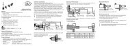
Sensor Mounting, Diffuse Reflection<br />
The <strong>optoNCDT</strong> <strong>2300</strong> sensor is an optical system for measurements with micrometer accuracy.<br />
i<br />
Make sure it is handled carefully when installing and operating!<br />
Mount the sensor by means of 3 screws type M4. The bearing surfaces surrounding the<br />
fastening holes (through-holes) are slightly raised.<br />
Diffuse Reflection, Dimensions and free space,<br />
Measuring ranges 2/10/20/50/100 mm<br />
75 (2.95)<br />
67 (2.64)<br />
4 (0.16)<br />
SMR<br />
MR<br />
<br />
97 (3.82)<br />
89 (3.50)<br />
80 (3.15) 30 (1.18)<br />
A<br />
B<br />
ø4 (0.16 dia.)<br />
13.4 (0.53)<br />
<br />
<br />
3 x Mounting<br />
hole ø 4.5 (.18 dia.)<br />
Start of measuring range<br />
End of measuring range<br />
37.5 (1.48)<br />
14 (0.55)<br />
15 (0.59)<br />
Laser off<br />
In range<br />
Midrange<br />
Error<br />
EtherCAT Ethernet<br />
RUN<br />
Power on<br />
ERR<br />
<strong>optoNCDT</strong><br />
Diffuse reflection<br />
MR = Measuring range<br />
SMR = Start of measuring range<br />
<strong>MB</strong>M = Midrange<br />
<strong>MB</strong>E = End of measuring range<br />
MR 2 10 20 50 100<br />
SMR 24 30 40 45 70<br />
MMR 25 35 50 70 120<br />
EMR 26 40 60 95 170<br />
a 35.0 31.7 26.4 25.0 18.6<br />
j 41.3 35.2 27.7 21.0 13.9<br />
e 47.5 38.2 28.6 19.2 11.8<br />
A 28.5 31.6 32.9 33.2 35.6<br />
B 16.7 18.4 19.8 20.9 23.5<br />
Direct Reflection, Dimensions and free space,<br />
Measuring ranges 2/10/20 mm<br />
75 (3.0)<br />
67 (2.6)<br />
4<br />
4<br />
33.5<br />
SMR + 0.5 MR<br />
4.5<br />
MR SMR + 0.5 MR alpha<br />
2 25 20.5 °<br />
10 35 17.5 °<br />
20 50 13.8 °<br />
SMR = Start of measuring range<br />
MR = Measuring range<br />
10<br />
13.5<br />
97 (3.8)<br />
89 (3.5)<br />
48<br />
In case of bore holes, blind holes, and<br />
edges in the surface of moving targets<br />
the sensor must be arranged in such a<br />
way that the edges do not obscure the<br />
laser spot.<br />
2<br />
alpha<br />
MR (dir.R)<br />
Limits for free<br />
Space<br />
Mounting holes<br />
3x ø4.5 (dia. .18)<br />
for M4 screws<br />
correct<br />
Laser o f<br />
In range<br />
Midrange<br />
Error<br />
EtherCAT Ethernet<br />
RUN<br />
Power on<br />
ERR<br />
<strong>optoNCDT</strong><br />
LASER RADIATION<br />
Do not stare into beam<br />
Class 2 Laser Product<br />
IEC 60825-1: 2008-05<br />
P = 1 mW; P = 1.2 mW; t=0.5 .542 µs<br />
F=1.5 .50 kHz; =670 nm<br />
Direct reflection<br />
Mounting steps<br />
Switch on the supply voltage<br />
on the sensor.<br />
Watch the “State“ LED on the<br />
top side of the sensor.<br />
Position a shining or mirroring<br />
measuring object within<br />
the measuring range.<br />
Move the fit-up aid between<br />
sensor and measuring object.<br />
The “State“ LED illuminates yellow.<br />
Mount the sensor by means<br />
of 3 screws type M4.<br />
Remove the fit-up aid between<br />
sensor and measuring<br />
object.<br />
incorrect<br />
(shadow)<br />
Input and Output<br />
Signal Sensor<br />
Cable PC<strong>2300</strong>-x/SUB-D 1<br />
Comment<br />
Designation Pin<br />
15-pol. Sub-D<br />
+ U b<br />
1 Supply voltage (11 ... 30 VDC) 1<br />
Ground 2<br />
System ground for supply and ground potential<br />
for RS422-level<br />
9<br />
+Laser on/off 3 optocoupler input, potential-free<br />
2<br />
- Laser on/off 4<br />
Laser off: U E<br />
≤ 0,8 V (Low)<br />
Laser on: 2,8 V ≤ U E<br />
≤ 30 V (High)<br />
10<br />
Sync-in/out 2 5<br />
Synchronous- respectively trigger signals,<br />
symmetrically, RS422-Pegel, terminating<br />
3<br />
/Sync-in/out 2 6<br />
resistor 120 Ohm switchable, input or output<br />
selected depending on the synchronization<br />
mode<br />
11<br />
RxD-RS422 7 Serial input RS422, symmetrically,<br />
4<br />
/RxD-RS422 8 Internally terminated with 120 Ohm<br />
12<br />
TxD-RS422 9<br />
5<br />
Serial output RS422, symmetrically<br />
/TxD-RS422 10 13<br />
Tx - Ethernet 11<br />
6<br />
Ethernet output, potential-free<br />
/Tx - Ethernet 12 14<br />
Rx - Ethernet 13<br />
7<br />
Ethernet input, potential-free<br />
/Rx - Ethernet 14 15<br />
Screen Housing No galvanic connection to ground Housing<br />
1) Further cables are available optionaly.<br />
2) In trigger operation the input is used for triggering.<br />
Plug connector: ODU MINI-SNAP, 14-pol., series B, dimension 2,<br />
code F, IP 68. Sensor round pin plug, view: Solder-pin side male cable<br />
connector<br />
Supply Voltage, Nominal value: 24 V DC (11 ... 30 V, max. 150 mA).<br />
11 ...<br />
30 VDC<br />
Laser on<br />
Type 1<br />
1<br />
2<br />
Laser off:<br />
U OUT<br />
< 0.8 V<br />
Laser on:<br />
2.8 V < U OUT<br />
< 30 V<br />
ILD <strong>2300</strong><br />
Sensor<br />
Pin<br />
PC<strong>2300</strong>-x/Y<br />
Color<br />
Supply<br />
1 white +U B<br />
2 brown Ground<br />
PC<strong>2300</strong>-x/Y +UB<br />
white 1<br />
ca. 5 mA<br />
green 3<br />
yellow<br />
4<br />
brown 2<br />
max.<br />
30 V<br />
Ground<br />
ILD <strong>2300</strong><br />
3<br />
2<br />
4<br />
1<br />
12<br />
11<br />
13<br />
10<br />
5 6<br />
Use supply voltage for measurement instruments<br />
only. MICRO-EPSILON recommends<br />
using an optional available power<br />
supply unit PS2020 for the sensor.<br />
i<br />
If pin Pin 3 with +U B<br />
and Pin 4 are<br />
not connected with ground, the<br />
laser is off.<br />
MICRO-EPSILON MESSTECHNIK<br />
GmbH & Co. KG<br />
Königbacher Str. 15 · 94496 Ortenburg<br />
www.micro-epsilon.de<br />
14<br />
9<br />
7<br />
*X9771234-A05*<br />
8<br />
X9771234-A051054HDR<br />
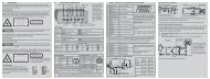
Warnings<br />
<strong>Assembly</strong> Instructions<br />
<strong>optoNCDT</strong> <strong>2300</strong><br />
Avoid unnecessary laser radiation to be exposed to the human body. Switch off the sensor for cleaning<br />
and maintenance, for system maintenance and repair if the sensor is integrated into a system.<br />
Caution - use of controls or adjustments or performance of procedures other than those specified<br />
may cause harm.<br />
Connect the power supply and the display-/output device in accordance with the safety regulations<br />
for electrical equipment. The power supply may not exceed the specified limits.<br />
> > Danger of injury. Damage to or destruction of the sensor.<br />
Avoid continuous exposure to fluids on the sensor. Avoid exposure to aggressive materials (washing<br />
agent, penetrating liquids or similar) on the sensor.<br />
> > Damage to or destruction of the sensor.<br />
Avoid shock and vibration to the sensor. Protect the sensor cable against damage.<br />
> > Damage to or destruction of the sensor , failure of the measuring device.<br />
Proper Use<br />
The <strong>optoNCDT</strong> <strong>2300</strong> system is designed for use in industrial and laboratory areas.<br />
It is used for measuring displacement, distance, position and elongation for in-process quality control<br />
and dimensional testing<br />
The sensor may only be operated within the limits specified in the technical data, see instruction<br />
manual, Chap. 3.4. Use the sensor in such a way that in case of malfunctions or failure personnel or<br />
machinery are not endangered.<br />
Take additional precautions for safety and damage prevention for safety-related applications.<br />
Laser Class<br />
The <strong>optoNCDT</strong> <strong>2300</strong> sensors operate with a semiconductor laser with a wavelength of 670 nm (visible/red<br />
ILD <strong>2300</strong>-x) resp. 405 nm (visible/blue ILD <strong>2300</strong>-xBL).<br />
The following warning labels are attached to the cover (front and/or rear side) of the sensor housing:<br />
LASER RADIATION<br />
Do not stare into beam<br />
Class 2 Laser Product<br />
IEC 60825-1: 2008-05<br />
P0= 1 mW; PP<br />
= 1.2 mW; t=0.5...542 µs<br />
F=1.5...50 kHz; =670 nm<br />
THIS PRODUCT COMPLIES<br />
WITH FDA REGULATIONS<br />
21CFR 1040.10 AND 1040.11<br />
LASER RADIATION<br />
Do not stare into beam<br />
Class 2 Laser Product<br />
IEC 60825-1: 2008-05<br />
P0= 1 mW; PP<br />
= 1.2 mW; t=0.5...542 µs<br />
F=1.5...50 kHz; =405 nm<br />
IEC label Only for USA IEC label for ILD<strong>2300</strong>-x BL<br />
Never deliberately look into the laser beam! Consciously close your eyes or<br />
turn away immediately if ever the laser beam should hit your eyes.
0<br />
P<br />
0<br />
P<br />
0<br />
Diffuse Reflection, Dimensions for measuring range 200 mm<br />
EtherCAT Connection<br />
Select a Measuring Program<br />
Displacement Measuring<br />
150 (5.90)<br />
140 (5.51)<br />
130 (5.52)<br />
35 (1.38)<br />
Patch cable<br />
Go to the menu Preferences > Measuring program.<br />
Select Diffuse reflection from the measurement arrangement list. Confirm with Apply.<br />
Go to the menu Measurement.<br />
Disable the Autoscale function and click on the Start button.<br />
80 (3.15)<br />
70 (2.76)<br />
SMR<br />
MR<br />
91.6 (3.61)<br />
76 (2.99)<br />
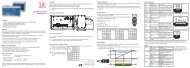
Quick Guide<br />
Components<br />
ø5 (1.20 dia.)<br />
15 (0.59)<br />
<br />
<br />
<br />
--<br />
Sensor<br />
--<br />
Power supply<br />
--<br />
Laptop / PC + USB/Ethernet adapter + Ethernet cable<br />
Mount the sensor and connect the components together.<br />
Ethernet Connection<br />
= 13.1 °<br />
= 16.7 °<br />
= 25.1 °<br />
Start of measuring range<br />
End of measuring range<br />
3 x Mounting<br />
hole ø4.5<br />
(0.18 dia.)<br />
12 (0.47)<br />
17.5 (0.69)<br />
Patch cable<br />
Laser off EtherCAT Ethernet<br />
In range<br />
RUN<br />
Midrange<br />
Power on<br />
Error<br />
ERR<br />
Measuring object<br />
<strong>optoNCDT</strong><br />
LASER RADIATION<br />
Do not stare into beam<br />
Class 2 Laser Product<br />
IEC 60825-1: 2008-05<br />
P = 1 mW; P = 1.2 mW; t=0.5...542 µs<br />
F=1.5...50 kHz; =670 nm<br />
Commissioning<br />
PC<strong>2300</strong>-x/SUB-D<br />
PC<strong>2300</strong>-0,5/Y<br />
PS2020<br />
PS2020<br />
N<br />
L<br />
230 VAC<br />
The sensor is delivered ex factory with the IP<br />
address 169.254.168.150.<br />
PE<br />
Run<br />
X1<br />
X2<br />
BECKHOFF EK1122<br />
You can check the IP address of the sensors, that<br />
are connected to a PC / network, with the<br />
SensorFinder.exe. program. You will find this program<br />
on the provided CD.<br />
Now start the program SensorFinder.exe and<br />
click on the button Find sensors.<br />
Select the designated sensor from the list.<br />
Click the button Start browser to connect<br />
the sensor with your default browser.<br />
Alternatively: If DHCP is enabled and the DHCP<br />
server is linked with the DNS server, an access is<br />
possible on „ILD<strong>2300</strong>_SN01234567“ („01234567“<br />
Serial number of your sensor).<br />
Select a Measuring Rate<br />
Go to the menu Preferences > Measuring rate.<br />
Start with a medium measuring rate. Select a measuring rate from the list. Confirm with Apply.<br />
Select a Digital Interface<br />
Go to the menu Preferences > Digital interfaces > Selection of digital<br />
interfaces.<br />
Select Web Diagram from the list. Confirm with Apply.<br />
Store the Settings<br />
Go to the menu Preferences > Load/save settings.<br />
Select Parameter set from the data selection list, a parameter set number and click on the<br />
button Save.<br />
Position a Measuring Object<br />
Position a measuring object (target) as possible in the midrange.<br />
EtherCAT Ethernet<br />
Laser off<br />
RUN<br />
In range<br />
Power on<br />
Midrange<br />
ERR<br />
Error<br />
NCDT<br />
opto<br />
LASER RADIATION<br />
Do not stare into beam<br />
Class 2 Laser Product<br />
IEC 60825-1: 2008-05<br />
P = 1 mW; P P = 1.2 mW; t=0.5...542 µs<br />
F=1.5...50 kHz; =670 nm<br />
100 %<br />
Signal<br />
50<br />
0<br />
SMR<br />
SMR MMR EMR<br />
Measuring range<br />
Measuring object<br />
Displacement<br />
The Status LED Status on the sensor indicates the position of the measuring object to the sensor.<br />
Thickness Measurement<br />
Got to the menu Preferences > Measuring program and select Direct reflection<br />
- thickness measurement from the measurement arrangement list.<br />
Select the target material from the material list. Confirm with Apply.<br />
Store the Settings<br />
Go to the menu Preferences > Load/save settings.<br />
Select Parameter set from the data selection list, a parameter set number and click on<br />
the button Save.<br />
Laser off EtherCAT Ethernet<br />
In range<br />
RUN<br />
Midrange<br />
Power on<br />
Error<br />
ERR<br />
<strong>optoNCDT</strong><br />
LASER RADIATION<br />
Do not stare into beam<br />
Class 2 Laser Product<br />
IEC 60825-1: 2008-05<br />
P = 1 mW; P = 1.2 mW; t=0.5...542 µs<br />
F=1.5...50 kHz; =670 nm<br />
Measuring object<br />
PC<strong>2300</strong>-x/SUB-D<br />
PC<strong>2300</strong>-0,5/Y<br />
PS2020<br />
PS2020<br />
N L<br />
PE<br />
230 VAC<br />
Start a web browser on your PC. Type<br />
„ILD<strong>2300</strong>_Serial number“ in the address bar of<br />
your web browser.<br />
Interactive websites for programming the sensor<br />
now appear in the web browser.<br />
If you have changed any settings, go to the<br />
menu Preferences and click on the button<br />
Save Setup to store your settings.<br />
LED Color Labeling Meaning<br />
Status<br />
off Laser off Laser beam is switched off<br />
green In range Sensor operates, measuring object within measuring range<br />
yellow Midrange<br />
red<br />
Error<br />
Measuring object is in midrange<br />
Measuring object outside measuring range,<br />
reflection is to low<br />
Read the detailed instruction manual before using the sensor. The manual is available online on<br />
www.micro-epsilon.com/download/manuals/man--<strong>optoNCDT</strong>-<strong>2300</strong>--en.pdf or on the supplied<br />
CD.