Bomem-GRAMS User's Guide
Bomem-GRAMS User's Guide
Bomem-GRAMS User's Guide

You also want an ePaper? Increase the reach of your titles
YUMPU automatically turns print PDFs into web optimized ePapers that Google loves.
<strong>Bomem</strong>-<strong>GRAMS</strong><br />
<strong>User's</strong> <strong>Guide</strong><br />
This manual contains: Information on installing <strong>Bomem</strong>-<strong>GRAMS</strong>, and using the Collect menu<br />
commands.<br />
IMZ9013<br />
Revision 1.1 March 2003
Copyright<br />
© 2001 - 2003 ABB <strong>Bomem</strong> Inc. All Rights Reserved.<br />
This <strong>Guide</strong> and the accompanying software are copyrighted and all rights are<br />
reserved by ABB Inc. henceforth ABB. This product, including software and<br />
documentation, may not, in whole or in part, be copied, photocopied,<br />
reproduced, translated, or reduced to any electronic medium or machinereadable<br />
form without prior consent, in writing, from ABB.<br />
Windows NT, Windows 2000 and Windows XP are trademarks of Microsoft<br />
Corporation. All rights reserved.<br />
License and<br />
Limited Warranty<br />
Agreement<br />
Important:<br />
This software product is sold by ABB with the following Software License,<br />
Software Disclaimer of Warranty, and Hardware Limited Warranty<br />
(collectively, the Agreement).<br />
READ THIS AGREEMENT CAREFULLY BEFORE OPENING THE DISKS<br />
AND ASSOCIATED SOFTWARE PACKAGES. OPENING THE DISKS AND<br />
SOFTWARE PACKAGES INDICATES YOUR UNDERSTANDING AND<br />
ACCEPTANCE OF THIS AGREEMENT.<br />
If you do not agree to the terms contained below, return the product with the<br />
package disks unopened to your distributor and the purchase price will be<br />
refunded. ABB agrees to grant and the licensee agrees to accept on the following<br />
terms and conditions, non-transferable (except as herein defined) and nonexclusive<br />
licenses to the software program(s) (Licensed Programs) herein<br />
delivered with this agreement.<br />
Software license<br />
Each software license granted under this Agreement authorizes the licensee to<br />
use the Licensed Programs in a machine-readable form on any single computer<br />
with a single specific ABB spectrometer. A separate license is required for each<br />
single computer and/or each single ABB spectrometer on which the Licensed<br />
Programs will be used.<br />
This Agreement and any of the licenses, programs, or materials to which it<br />
applies may not be assigned, sublicensed, or otherwise transferred by the<br />
licensee without prior written consent from ABB, except as herein after<br />
expressly provided.<br />
<strong>Bomem</strong>-<strong>GRAMS</strong> <strong>User's</strong> <strong>Guide</strong><br />
iii
No right to print, copy, in whole or in part, the Licensed Programs is granted<br />
except as herein after expressly provided. You may copy the Licensed Programs<br />
solely for backup purposes as long as this copyright is reproduced along with<br />
the backup copies.<br />
You may physically transfer the Licensed Programs from one computer to<br />
another provided that the Licensed Programs are only used on one computer at a<br />
time and only with the specific ABB instrument they were supplied for.<br />
Software disclaimer<br />
of warranty and<br />
hardware limited<br />
warranty<br />
ABB makes no representations or warranties with regard to this software and<br />
instructional and reference materials, including, but not limited to, the implied<br />
warranties of merchantability and fitness for a particular purpose.<br />
ABB does not warrant, guarantee, or make any representations regarding the<br />
use, or the results of the use, of the software or written material in terms of<br />
correctness, accuracy, reliability, currentness, or otherwise.<br />
ABB shall not be liable for errors or omissions contained in its software or<br />
manuals or incidental or consequential damages in connection with<br />
the furnishing, performance, or use of these materials even if ABB has been<br />
advised of the possibility of such damages. The software and manuals are sold<br />
as is. The entire risk as to the results and performance of the software is assumed<br />
by you.<br />
ABB warrants to the original licensee that the disks on which the software is<br />
recorded are free from defects in materials and workmanship for a period of<br />
ninety (90) days from the date of delivery. ABB’s entire liability and your<br />
exclusive remedy as to the disks shall be, at ABB’s option, either:<br />
(a) return of the purchase price or<br />
(b) replacement of the disk that does not meet this Limited Warranty.<br />
THE ABOVE ARE THE ONLY WARRANTIES OF ANY KIND, EITHER<br />
EXPRESS OR IMPLIED, INCLUDING BUT NOT LIMITED TO THE IMPLIED<br />
WARRANTIES OF MERCHANTABILITY AND FITNESS FOR A<br />
PARTICULAR PURPOSE, THAT ARE MADE BY ABB ON THIS PRODUCT.<br />
BECAUSE SOME STATES DO NOT ALLOW THE EXCLUSION OR<br />
LIMITATION OF LIABILITY OR CONSEQUENTIAL OR INCIDENTAL<br />
DAMAGES, THE ABOVE LIMITATION MAY NOT APPLY TO YOU.<br />
iv<br />
<strong>Bomem</strong>-<strong>GRAMS</strong> <strong>User's</strong> <strong>Guide</strong>
Customer support<br />
ABB provides product support services throughout the world. To receive<br />
product support, either in or out of warranty, contact the ABB office that serves<br />
your geographical area, or the office shown below:<br />
ABB <strong>Bomem</strong> Inc.<br />
585, Charest Blvd. East, suite 300<br />
Québec, Québec G1K 9H4<br />
CANADA<br />
Tel.: (418) 877-2944 or<br />
(800) 858-FTIR (in North America)<br />
Fax: (418) 877-2834<br />
E-mail: bomem_service@ca.abb.com<br />
You can also consult ABB’s web site at www.abb.com/analytical<br />
<strong>Bomem</strong>-<strong>GRAMS</strong> <strong>User's</strong> <strong>Guide</strong><br />
v
T ABLE OF CONTENTS<br />
About this Manual............................................................................................................................................ ix<br />
1. Quick Start................................................................................................................................................. 1<br />
1.1 Check the signal.............................................................................................................................. 1<br />
1.2 Acquire a background spectrum ..................................................................................................... 5<br />
1.3 Acquire a sample spectrum............................................................................................................. 6<br />
2. <strong>Bomem</strong>-<strong>GRAMS</strong>........................................................................................................................................ 9<br />
2.1 Description ..................................................................................................................................... 9<br />
3. Software Installation ............................................................................................................................... 11<br />
3.1 Software description ..................................................................................................................... 11<br />
3.2 Computer requirements ................................................................................................................ 12<br />
3.3 Software installation ..................................................................................................................... 12<br />
4. The Collect Menu .................................................................................................................................... 15<br />
4.1 Description ................................................................................................................................... 15<br />
4.1.1<br />
4.1.2<br />
Setup............................................................................................................................... 15<br />
Align............................................................................................................................... 22<br />
4.1.3<br />
4.1.4<br />
Collect ............................................................................................................................ 24<br />
Instrument Status and Control........................................................................................ 27<br />
4.1.5 Halt Collect ....................................................................................................................29<br />
4.1.5.1<br />
4.1.5.2<br />
Data acquisition initiated by the Align command ........................................ 29<br />
Data acquisition initiated by the Collect command ...................................... 29<br />
4.1.6 Help................................................................................................................................ 30<br />
A Apodization Functions ............................................................................................................................ 31<br />
A.1 Purpose ......................................................................................................................................... 31<br />
A.2 Functions available in <strong>Bomem</strong>-<strong>GRAMS</strong>...................................................................................... 31<br />
B Array Basic Interface .............................................................................................................................. 33<br />
B.1 Array Basic methods .................................................................................................................... 33<br />
B.2 Array Basic Properties.................................................................................................................. 38<br />
B.3 Error codes.................................................................................................................................... 41<br />
<strong>Bomem</strong>-<strong>GRAMS</strong> <strong>User's</strong> <strong>Guide</strong><br />
vii
C Audit Log ..................................................................................................................................................45<br />
D Glossary ....................................................................................................................................................47<br />
Index of Dialog boxes.......................................................................................................................................59<br />
Index..................................................................................................................................................................61<br />
viii<br />
<strong>Bomem</strong>-<strong>GRAMS</strong> <strong>User's</strong> <strong>Guide</strong>
ABOUT THIS M ANUAL<br />
Audience<br />
a This appendix is intended<br />
for people who will be<br />
programming in the Array<br />
Basic language.<br />
This manual is intended for personnel installing <strong>Bomem</strong>-<strong>GRAMS</strong> (which<br />
consists of <strong>GRAMS</strong>/AI or <strong>GRAMS</strong>/LT and the added Collect menu) and using<br />
the Collect menu commands. Please refer to the following chapters:<br />
For information on:<br />
Refer to:<br />
Installing <strong>Bomem</strong>-<strong>GRAMS</strong> Chapter 3 Software Installation<br />
Using the Collect menu commands Chapter 1 Quick Start<br />
Chapter 4 The Collect Menu<br />
The apodization functions used by<br />
Appendix A Apodization Functions<br />
the software.<br />
The Array Basic extensions related to<br />
the Michelson Collect Driver. a<br />
<br />
Appendix B Array Basic Interface<br />
For information on <strong>GRAMS</strong>/AI software and the Array Basic language,<br />
refer to the manuals from Thermo Galactic. These manuals are included<br />
with your spectrometer.<br />
Note: <strong>GRAMS</strong>/LT is a simplified version of <strong>GRAMS</strong>/AI. It can be provided by<br />
ABB with the purchase of certain instruments.<br />
Conventions used<br />
in ABB manuals<br />
Software commands and dialog box names and are shown in boldface type.<br />
Text to be entered into software is in sans serif type.<br />
<br />
This symbol refers you to another manual or document.<br />
Note: Supplemental information to help the reader.<br />
Important: Information that is important, but that does not concern the safe use<br />
of the equipment.<br />
This symbol shows that Caution is required. Follow<br />
the instructions carefully to avoid damage to the equipment.<br />
WARNING! Failure to comply with warnings can result in serious injury<br />
or loss of life.<br />
<strong>Bomem</strong>-<strong>GRAMS</strong> <strong>User's</strong> <strong>Guide</strong><br />
ix
CHAPTER 1<br />
QUICK START<br />
This Quick Start guides you in acquiring the transmittance spectrum of a sample<br />
using <strong>Bomem</strong>-<strong>GRAMS</strong>, once the program has been installed (see Chapter 3 on<br />
page 11).<br />
Note: All commands used in this section are in the Collect menu and are<br />
described in detail in Chapter 4 on page 15.<br />
<br />
For information on the other functions in <strong>Bomem</strong>-<strong>GRAMS</strong>, refer to<br />
the <strong>GRAMS</strong>/AI manuals from Thermo Galactic. These manuals are<br />
included with your spectrometer.<br />
1.1 Check the signal<br />
1. Make sure that the sampling accessory or sample holder is properly<br />
installed and that there are no objects or sample in the sampling area.<br />
(This condition is called “open beam”.)<br />
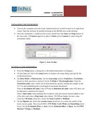
2. Start <strong>Bomem</strong>-<strong>GRAMS</strong> (see Figure 1-1 below).<br />
Figure 1-1. Starting <strong>Bomem</strong>-<strong>GRAMS</strong><br />
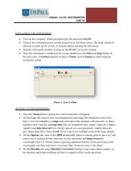
3. Select Setup in the Collect menu. Once the connected instruments have<br />
been detected the Parameters Setup dialog box (see Figure 1-2 on page 2)<br />
will be displayed. Use the Acquisition Card list box to select one of<br />
the connected instruments.<br />
Make sure that all of the parameters on the four tabs are set correctly<br />
(refer to the Section 4.1.1 on page 15).<br />
<strong>Bomem</strong>-<strong>GRAMS</strong> <strong>User's</strong> <strong>Guide</strong> 1
Section 1.1<br />
Check the signal<br />
Figure 1-2. Parameter Setup dialog box<br />
4. Set the spectrometer resolution to 4 cm -1 . If the spectrometer has a manual<br />
resolution switch, turn the knob to 4. If the spectrometer resolution is<br />
computer controlled, select Instrument Status and Control and set<br />
the Resolution to 4 (see Figure 1-3 below).<br />
Figure 1-3. Instrument Status and Control dialog box<br />
5. Select Align to display the Align dialog box (see Figure 1-4 on page 3).<br />
2 <strong>Bomem</strong>-<strong>GRAMS</strong> <strong>User's</strong> <strong>Guide</strong>
Chapter 1<br />
Quick Start<br />
Figure 1-4. Align dialog box<br />
Set the parameters as follows:<br />
Spectral Range Start and End:<br />
• for MIR: 4000 to 400 cm -1<br />
• for NIR: 14 000 to 4000 cm -1<br />
Show Scan direction: Both directions<br />
Data type: Single-Beam<br />
6. Click OK Align to begin data acquisition in the align mode. This will allow<br />
you to make sure the spectra will be properly acquired without detector<br />
saturation.<br />
In the align mode, the display is continuously updated until the Halt Collect<br />
command is selected. No data is saved in this mode.<br />
7. Observe the displayed spectrum. The word Align near the upper right<br />
corner of the display indicates the interferogram amplitude as a percentage<br />
of the maximum allowed (refer to Maximum interferogram amplitude<br />
allowed on page 21). This percentage should be between 40% and 90%.<br />
8. Check for any unusual spectral features such as a strong signal below<br />
the detector cut-off frequency (usually caused by detector saturation).<br />
Note: <strong>Bomem</strong>-<strong>GRAMS</strong> can automatically detect this condition. Refer to<br />
Optical Cut-Off Detection on page 21.<br />
Figure 1-5 on page 4 shows typical open-beam spectra for MIR<br />
(mid infrared) and NIR (near infrared).<br />
<strong>Bomem</strong>-<strong>GRAMS</strong> <strong>User's</strong> <strong>Guide</strong> 3
Section 1.1<br />
Check the signal<br />
Figure 1-5. Typical open-beam spectra<br />
Figure 1-6 below presents MIR spectra showing detector saturation.<br />
Highly<br />
saturated<br />
Saturated<br />
Normal<br />
Figure 1-6. MIR spectra showing detector saturation<br />
9. Select Halt to stop data acquisition.<br />
4 <strong>Bomem</strong>-<strong>GRAMS</strong> <strong>User's</strong> <strong>Guide</strong>
Chapter 1<br />
Quick Start<br />
1.2 Acquire<br />
a background<br />
spectrum<br />
1. Select Collect to display the Collect dialog box (see Figure 1-7 below).<br />
Set the parameters as follows:<br />
Acquisition type: Background<br />
General Param:<br />
• Number of Scans: 10 or more<br />
File Name: Enter a file name (up to 144 characters).<br />
The program will automatically add the extension shown.<br />
Use Auto Gain: Select this option.<br />
2. Click OK Collect to begin data acquisition.<br />
During data acquisition the spectrum of each individual scan is displayed on<br />
the page. When all the spectra are acquired, the coadded spectrum is<br />
displayed and saved.<br />
Figure 1-7. Collect dialog box<br />
<strong>Bomem</strong>-<strong>GRAMS</strong> <strong>User's</strong> <strong>Guide</strong> 5
Section 1.3<br />
Acquire a sample spectrum<br />
1.3 Acquire<br />
a sample<br />
spectrum<br />
1. When the background spectrum has been acquired, insert the sample in<br />
the sample holder or sampling accessory.<br />
For an FT-IR series spectrometer:<br />
• For MIR, use the polystyrene sample supplied with<br />
the spectrometer (see Figure 1-8 below).<br />
• For NIR, do not use the polystyrene sample. Instead, place an<br />
ordinary plastic bag over the sample holder.<br />
For another model of spectrometer, use a sample of the appropriate type.<br />
Figure 1-8. Inserting the polystyrene sample into the sample holder of an MB Series spectrometer<br />
2. Select Collect to display the Collect dialog box (see Figure 1-7 on page 5).<br />
Set the parameters as follows:<br />
Acquisition type: Normal<br />
Spectral Range Start and End:<br />
• for MIR: from 4000 to 400 cm -1<br />
• for NIR: from 14 000 to 4000 cm -1<br />
General Param:<br />
• Initial Delay: 0<br />
• Number of scans: 10 or more<br />
6 <strong>Bomem</strong>-<strong>GRAMS</strong> <strong>User's</strong> <strong>Guide</strong>
Chapter 1<br />
Quick Start<br />
File Name: Enter a file name (up to 144 characters).<br />
The program will automatically add the extension shown.<br />
Use Auto Gain: Select this option.<br />
Data type: %Trans<br />
Background: This should be the name of the background file enter in<br />
step 1 of Section 1.2.<br />
3. Click OK Collect to begin data acquisition.<br />
During data acquisition the spectrum of each individual scan is displayed on<br />
the page. When all the spectra are acquired, the coadded spectrum is<br />
displayed and saved.<br />
4. Observe the acquired spectrum.<br />
Figure 1-9 below shows an example of the transmittance spectrum of<br />
a polystyrene sample in the MIR range and the transmittance spectrum of<br />
a plastic bag in the NIR range.<br />
Figure 1-9. Transmittance spectra<br />
<strong>Bomem</strong>-<strong>GRAMS</strong> <strong>User's</strong> <strong>Guide</strong> 7
CHAPTER 2<br />
BOMEM-<strong>GRAMS</strong><br />
2.1 Description<br />
<strong>GRAMS</strong>/LT is a simplified<br />
version of <strong>GRAMS</strong>/AI. It can<br />
be provided by ABB with the<br />
purchase of certain<br />
instruments.<br />
<strong>Bomem</strong>-<strong>GRAMS</strong> is a program for spectral acquisition, display, and processing<br />
that can interact directly with an ABB FT-IR instrument.<br />
<strong>Bomem</strong>-<strong>GRAMS</strong> consists of the following components, which are installed<br />
separately. These components are included on the ABB and Thermo Galactic<br />
Products CD-ROM:<br />
• <strong>GRAMS</strong>/AI (or <strong>GRAMS</strong>/LT) version 7 from Thermo Galactic<br />
• the Michelson Collect Driver from ABB<br />
Note: This manual assumes that the user already be familiar with<br />
the <strong>GRAMS</strong>/AI environment. This manual does not attempt to document<br />
<strong>GRAMS</strong>/AI software or the Array Basic language.<br />
The present version of <strong>GRAMS</strong>/AI from Thermo Galactic is designed to run on<br />
Windows NT, Windows 2000 and Windows XP. This version uses the driver<br />
technology called “My Instrument”. With this feature, when a compatible “My<br />
Instrument” control program is detected on the computer, <strong>GRAMS</strong>/AI will<br />
automatically add a Collect menu that will link to the instrument. When any<br />
command in the Collect menu is used, a new page will automatically be added<br />
to the current workbook with a link to the instrument.<br />
Installing the Michelson Collect Driver adds the Collect menu (see Figure 2-1<br />
below) to <strong>GRAMS</strong>/AI and allows <strong>GRAMS</strong>/AI to communicate with ABB FT-IR<br />
instruments. Once the Collect menu has been added to <strong>GRAMS</strong>/AI, the<br />
software is referred to as <strong>Bomem</strong>-<strong>GRAMS</strong>.<br />
Figure 2-1. Collect menu<br />
<strong>Bomem</strong>-<strong>GRAMS</strong> <strong>User's</strong> <strong>Guide</strong> 9
CHAPTER 3<br />
SOFTWARE INSTALLATION<br />
Note: If the computer is supplied by ABB Inc., the software is already installed<br />
and configured.<br />
Administrator access privileges are required to install the Michelson<br />
Collect Driver.<br />
For convenience, this installation procedure is provided in this manual<br />
and in the FT-IR Spectrometer Ethernet Interface and External Ethernet<br />
for FT-IR <strong>User's</strong> <strong>Guide</strong>.<br />
3.1 Software<br />
description<br />
<strong>GRAMS</strong>/LT is a simplified<br />
version of <strong>GRAMS</strong>/AI. It can<br />
be provided by ABB with the<br />
purchase of certain<br />
instruments.<br />
This chapter shows how to install the following software:<br />
‣ Products from Thermo Galactic including <strong>GRAMS</strong>/AI (or <strong>GRAMS</strong>/LT)<br />
<strong>GRAMS</strong>/AI is a program for spectral acquisition, display, and processing.<br />
It also includes tools for building calibration models.<br />
‣ The Michelson Collect Driver from ABB. This includes the following<br />
components:<br />
• the ABB FT-IR Control Panel configuration applet (bodriv.cpl)<br />
This is used to configure the FT-IR Spectrometer Ethernet Interface of<br />
an instrument and to update the firmware.<br />
• the Acquisition DLL (bograms.dll)<br />
This enables applications to control and acquire data from ABB FT-IR<br />
instruments through the FT-IR Spectrometer Ethernet Interface.<br />
• the Collect menu. This menu is added to <strong>GRAMS</strong>/AI or <strong>GRAMS</strong>/LT<br />
and contains commands allowing you to set acquisition parameters for<br />
and acquire spectra from ABB FT-IR instruments.<br />
The Collect menu is part of an ActiveX acquisition interface (bgac.dll).<br />
The interface simplifies connecting to the FT-IR Spectrometer Ethernet<br />
Interface from any application that supports ActiveX.<br />
Note: Once the Collect menu has been added to <strong>GRAMS</strong>/AI, the software is<br />
referred to as <strong>Bomem</strong>-<strong>GRAMS</strong><br />
<strong>Bomem</strong>-<strong>GRAMS</strong> <strong>User's</strong> <strong>Guide</strong> 11
Section 3.2<br />
Computer requirements<br />
3.2 Computer<br />
requirements<br />
The minimum requirements for the computer are:<br />
• Pentium II class computer, 350 MHz, 128 MB RAM<br />
• Ethernet network adapter<br />
• Windows NT version 4.0 with Service Pack 6a<br />
Windows 2000<br />
Windows XP<br />
3.3 Software<br />
installation<br />
The software is installed using the following procedure:<br />
1. Insert the ABB and Thermo Galactic Products CD-ROM into the CD-ROM<br />
drive of the computer. The main menu should appear automatically (see<br />
Figure 3-1 below).<br />
Note:<br />
If the main menu fails to appear, using Windows Explorer, find and<br />
double click the file launch.exe on the CD-ROM.<br />
Figure 3-1. Main menu of installation program<br />
12 <strong>Bomem</strong>-<strong>GRAMS</strong> <strong>User's</strong> <strong>Guide</strong>
Chapter 3<br />
Software Installation<br />
2. Click the Install Products button. The Install Products screen<br />
(see Figure 3-2 below) will appear. This screen presents the lists of products<br />
available on the CD-ROM.<br />
Figure 3-2. Install Products screen<br />
3. Select Thermo Galactic Products to install Thermo Galactic products.<br />
The Typical installation option includes <strong>GRAMS</strong>/AI. If you perform<br />
a Custom installation be sure to include <strong>GRAMS</strong>/AI.<br />
4. Follow the screen prompts and refer to the documentation from Thermo<br />
Galactic to complete the installation.<br />
5. Start <strong>GRAMS</strong>/AI to complete the installation (see Figure 3-3 on page 14).<br />
Then exit <strong>GRAMS</strong>/AI.<br />
Note:<br />
It is important to start and exit <strong>GRAMS</strong>/AI at least once before<br />
proceeding with the installation.<br />
<strong>Bomem</strong>-<strong>GRAMS</strong> <strong>User's</strong> <strong>Guide</strong> 13
Section 3.3<br />
Software installation<br />
Figure 3-3. Starting <strong>GRAMS</strong>/AI<br />
6. Return to the Install Products screen and Select Michelson Collect Driver<br />
to install the driver.<br />
7. Return to the main menu and exit the program.<br />
8. Restart the computer.<br />
After these steps have been completed, the Collect menu will appear in<br />
the menu bar of <strong>GRAMS</strong>/AI.<br />
<br />
For information on the other menus in <strong>Bomem</strong>-<strong>GRAMS</strong>, refer to<br />
the <strong>GRAMS</strong>/AI manuals from Thermo Galactic. These manuals are<br />
included with your spectrometer.<br />
14 <strong>Bomem</strong>-<strong>GRAMS</strong> <strong>User's</strong> <strong>Guide</strong>
CHAPTER 4<br />
THE COLLECT MENU<br />
The user interface of <strong>Bomem</strong>-<strong>GRAMS</strong> is identical to that of the standard version<br />
of <strong>GRAMS</strong>/AI except for the addition of the Collect menu. This chapter<br />
describes the commands in the Collect menu.<br />
<br />
For information on the other commands in <strong>Bomem</strong>-<strong>GRAMS</strong>, refer to<br />
the <strong>GRAMS</strong>/AI manuals from Thermo Galactic. These manuals are<br />
included with your spectrometer.<br />
4.1 Description<br />
The Collect menu of <strong>Bomem</strong>-<strong>GRAMS</strong> contains all of the acquisition-related<br />
commands. These commands are shown in Figure 4-1 below and are described<br />
in the following sections.<br />
Figure 4-1. Collect menu<br />
Note: The standard toolbar is disabled while acquisition-related commands are<br />
executing.<br />
4.1.1 Setup<br />
The Setup command is used to set parameters that affect how spectrum<br />
acquisition is performed. Clicking Setup in the Collect menu displays<br />
the Parameter Setup dialog box. This dialog box has four tabs:<br />
• Hardware<br />
• Spectroscopic Parameters<br />
• Program<br />
• Saturation<br />
<strong>Bomem</strong>-<strong>GRAMS</strong> <strong>User's</strong> <strong>Guide</strong> 15
Section 4.1<br />
Description<br />
Parameter Setup: Hardware<br />
The Hardware tab is used to display and edit hardware parameters.<br />
• Instrument Type indicates the type of spectrometer or analyzer being used.<br />
This parameter cannot be edited in this dialog box; it is edited using the ABB<br />
FT-IR Control Panel applet.<br />
<br />
For information on using the Control Panel applet, refer to the FT-IR<br />
Spectrometer Ethernet Interface and External Ethernet Interface for<br />
FT-IR User’s <strong>Guide</strong>.<br />
• Acquisition card selects the type of acquisition card or instrument that will<br />
be used to acquire data. Note that only one instrument can be used at a time.<br />
The currently selected card or instrument is indicated by a symbol<br />
at the left of the name.<br />
A symbol indicates that the instrument is free, i.e. not already<br />
connected.<br />
16 <strong>Bomem</strong>-<strong>GRAMS</strong> <strong>User's</strong> <strong>Guide</strong>
Chapter 4<br />
The Collect Menu<br />
A symbol indicates that the instrument is busy and thus not<br />
available for connection.<br />
• Timeout sets the longest delay the program will wait before declaring that<br />
a hardware error has been detected.<br />
• Computer Controlled indicates that the instrument responds to computer<br />
commands. This parameter cannot be edited in the Hardware tab; it is edited<br />
using the ABB FT-IR Control Panel applet.<br />
• Detector selects the channel (detector) for which the first stage gain values<br />
are displayed. Depending on the selected instrument, the valid range is 1 or 2,<br />
or 1 to 64.<br />
• Use First Stage Gain and Use Second Stage Gain indicate that the gains on<br />
the first and second stages of the preamplifier are computer selectable. These<br />
parameters cannot be edited in the Hardware tab; they are edited using<br />
the ABB FT-IR Control Panel applet.<br />
• Use Default restores the default values.<br />
Parameter Setup: Spectroscopic Parameters<br />
The Spectroscopic Parameters tab is used to change the way spectra are<br />
calculated from the raw interferogram data.<br />
<strong>Bomem</strong>-<strong>GRAMS</strong> <strong>User's</strong> <strong>Guide</strong> 17
Section 4.1<br />
Description<br />
b The recommended setting<br />
for this field is Cosine.<br />
• Apodization b selects the apodization function that is applied to<br />
the interferogram before computing the Fast Fourier Transform (FFT).<br />
The available apodization functions are listed and described in Appendix A<br />
on page 31.<br />
• Laser Freq must be set to the frequency of the reference laser.<br />
This value should be 15799.7 for the red He-Ne laser used in all standard FT-<br />
IR Series spectrometers. Changing this value will render the data acquired<br />
incompatible with other data and with standard methods and libraries.<br />
• Absorbance Cut-Off min and Cut-Off max define the minimum and<br />
maximum values that any absorbance spectrum can reach.<br />
If the spectrum goes out of this range it is automatically truncated.<br />
• Transmittance Cut-Off min and Cut-Off max define the minimum and<br />
maximum values that any transmittance spectrum can reach.<br />
If the spectrum goes out of this range it is automatically truncated.<br />
18 <strong>Bomem</strong>-<strong>GRAMS</strong> <strong>User's</strong> <strong>Guide</strong>
Chapter 4<br />
The Collect Menu<br />
c For most applications, normal<br />
phase correction with Gaussian<br />
apodization and 128 cm -1<br />
resolution should be used.<br />
• Phase correction c affects the behaviour of the phase correction that is<br />
performed on the spectrum after computing the fast Fourier transform of<br />
the interferogram.<br />
Apodization selects the apodization function to use on the phase<br />
interferogram.<br />
Resolution selects the number of points to use for the apodization<br />
function.<br />
Type selects the interferogram from which the phase information is<br />
deduced:<br />
Normal selects the same interferogram as the sample.<br />
Stored selects an external interferogram stored in a file.<br />
• Use Default restores the default values.<br />
Parameter Setup: Program<br />
The Program tab shows parameters that affect the behaviour of the acquisition<br />
interface.<br />
<strong>Bomem</strong>-<strong>GRAMS</strong> <strong>User's</strong> <strong>Guide</strong> 19
Section 4.1<br />
Description<br />
• Buffer size allows changing the size of the FIFO (First In First Out memory)<br />
buffer that is used in the FT-IR Spectrometer Ethernet interface to hold<br />
spectra. The default value is recommended.<br />
• Overwrite warning when checked, the program will ask the user for<br />
confirmation before overwriting an existing file.<br />
d Some third-party software<br />
utilities may have trouble<br />
with floating-point format.<br />
However, files stored in this<br />
format can easily be<br />
converted to the <strong>GRAMS</strong><br />
format by loading them in<br />
<strong>Bomem</strong>-<strong>GRAMS</strong> and saving<br />
them under a new name.<br />
• File Format selects the format in which the files generated by the acquisition<br />
interface will be stored.<br />
IEEE floating-point format d stores the files in floating point format.<br />
This format is recommended because it provides better precision for<br />
the results.<br />
New SPC <strong>GRAMS</strong> format stores the files in the <strong>GRAMS</strong> SPC format.<br />
• Save Option determines whether the full or the specified spectral range is<br />
included in the saved spectrum files. This option is valid for the Absorbance<br />
and Transmittance data types only.<br />
• Use Default restores the default values.<br />
20 <strong>Bomem</strong>-<strong>GRAMS</strong> <strong>User's</strong> <strong>Guide</strong>
Chapter 4<br />
The Collect Menu<br />
Parameter Setup: Saturation<br />
The Saturation tab is used to set the parameters related to automatic saturation<br />
monitoring.<br />
e This value is also used as the<br />
target value for the maximum<br />
interferogram amplitude by<br />
the automatic gain setting<br />
function.<br />
• Maximum interferogram amplitude allowed e used to calculate<br />
the percentage values displayed by the align function and determines<br />
the saturation threshold for interferograms.<br />
• Optical Cut-Off Detection used to diagnose spectra for saturation<br />
(and/or nonlinearity).<br />
Spectral Range defines a region where each spectrum acquired by<br />
<strong>Bomem</strong>-<strong>GRAMS</strong> is tested by computing the average amplitude of<br />
the points in this region.<br />
The spectral range must be chosen to be below the cut-off of the detector<br />
and/or the optics. In mid IR, this will usually be below 400 cm -1 and in<br />
near IR, below 4000 cm -1 .<br />
<strong>Bomem</strong>-<strong>GRAMS</strong> <strong>User's</strong> <strong>Guide</strong> 21
Section 4.1<br />
Description<br />
Threshold determines the maximum value (in percentage) of the ratio of<br />
the average amplitude in the Spectral Range against the maximum<br />
spectrum amplitude.<br />
If the ratio is greater than the threshold value, a saturation warning is<br />
given to the user and put in the audit log (see Appendix C on page 45).<br />
• Use Default restores the default values.<br />
4.1.2 Align<br />
The Align command is used to display a spectrum or interferogram that is<br />
updated after each scan of the spectrometer. This is useful to adjust accessories<br />
for maximum throughput and to check if the signal intensity is acceptable.<br />
A readout of the ZPD amplitude as a percentage of the maximum allowed ZPD<br />
is also provided. When the Align command is selected, <strong>Bomem</strong>-<strong>GRAMS</strong><br />
switches to the page used for alignment and the Align dialog box appears.<br />
Align<br />
This dialog box is used to set align parameters before data acquisition is started.<br />
• Spectral Range Start and End define the displayed spectral region.<br />
• Show Scan direction allows showing the scans in one direction only<br />
(direction 0 or direction 1), or in both directions simultaneously.<br />
• Data type determines the type of data that will be displayed.<br />
IGram: raw interferogram<br />
Single-Beam: single-beam spectrum<br />
22 <strong>Bomem</strong>-<strong>GRAMS</strong> <strong>User's</strong> <strong>Guide</strong>
Chapter 4<br />
The Collect Menu<br />
f For transmittance spectrum<br />
and absorbance spectrum a<br />
background file is required.<br />
%Trans: transmittance spectrum f<br />
Absorb: absorbance spectrum f<br />
Background: the name of the current background (reference) file.<br />
• OK Align begins data acquisition.<br />
During this data acquisition, the display (see Figure 4-2 below) is continuously<br />
updated until the Halt Collect command (see Section 4.1.5 on page 29) is<br />
selected. No data is saved when using the Align command.<br />
1<br />
2<br />
8<br />
7<br />
6<br />
5<br />
3<br />
4<br />
Figure 4-2. Align display<br />
<strong>Bomem</strong>-<strong>GRAMS</strong> <strong>User's</strong> <strong>Guide</strong> 23
Section 4.1<br />
Description<br />
Number<br />
Identification<br />
1 Date and time<br />
2 Spectrum type<br />
3 Y-axis units<br />
4 X-axis units<br />
5 Interferogram ZPD amplitude as a percentage of the maximum allowed ZPD<br />
6 Scan speed in scans per minute<br />
(1 scan includes a forward and a reverse sweep)<br />
7 Resolution and instrument mode (Mid IR or Near IR)<br />
8 Number of scans<br />
4.1.3 Collect<br />
The Collect command is used for all data acquisition in <strong>Bomem</strong>-<strong>GRAMS</strong>.<br />
When the Collect command is selected, <strong>Bomem</strong>-<strong>GRAMS</strong> switches to the page<br />
used for data acquisition and the Collect dialog box appears.<br />
Collect<br />
This dialog box is used to set collect parameters before data acquisition is started.<br />
24 <strong>Bomem</strong>-<strong>GRAMS</strong> <strong>User's</strong> <strong>Guide</strong>
Chapter 4<br />
The Collect Menu<br />
g Spectra are acquired over<br />
the full spectral range unless<br />
specified otherwise in the<br />
Save Option parameter.<br />
• Acquisition type determines the type of data acquisition that will be used.<br />
Background: reference spectra<br />
Normal: normal spectra<br />
Kinetic: multifiles<br />
• Spectral Range Start and End define the displayed spectral region. g<br />
• General Param allows setting the following parameters:<br />
Initial Delay: delay in seconds before any scans are acquired.<br />
Number of Scans: number of scans to be averaged (coadded) together.<br />
Note: A scan is defined as a forward and a reverse sweep of the scan<br />
mechanism. Therefore, a single scan will result in two<br />
interferograms. The interferograms for forward sweeps and<br />
reverse sweeps are not combined, they are averaged separately.<br />
The forward and reverse sweep information is combined during<br />
the transformation from interferograms to spectra after the phase<br />
correction.<br />
• Use Auto Gain: When selected, determines the optimal gain setting using<br />
the first scan acquired.<br />
h When the Acquisition type is<br />
Kinetic, the gain is<br />
recalculated for each sub-file.<br />
The ZPD must be as close as possible to the maximum allowed ZPD without<br />
exceeding it. After the gain is determined, all scans are acquired using this<br />
gain setting. h All spectra are normalised with respect to the gain used so that<br />
they can be compared directly without scaling.<br />
The actual gain selected can be observed in real time with the Instrument<br />
Status and Control command (see Section 4.1.4 on page 27). The gain used<br />
is also stored in the resulting spectrum file in the audit log (see Appendix C<br />
on page 45).<br />
i When the Data type is<br />
transmittance or absorbance,<br />
a single beam file is also<br />
saved.<br />
• File Name indicates the name under which the files will be saved. This name<br />
can have a maximum length of 144 characters. The extension of the file is<br />
determined automatically and will depend on the type of data acquisition<br />
used. i The extension of the file will be one of the following:<br />
.interferogram.spc<br />
.background.spc<br />
.single beam.spc<br />
.transmittance.spc<br />
.absorbance.spc<br />
<strong>Bomem</strong>-<strong>GRAMS</strong> <strong>User's</strong> <strong>Guide</strong> 25
Section 4.1<br />
Description<br />
j For transmittance and<br />
absorbance spectra<br />
a background file is required.<br />
k Kinetic parameters are used<br />
when Kinetic is used as<br />
Acquisition type.<br />
Once a name is chosen, each time the Collect command is selected,<br />
the program will suggest this name with a number appended to it<br />
(the program will automatically increment the existing number).<br />
For example, if the first time the Collect command is selected the File Name<br />
is poly.absorbance.spc, the second time the command is selected<br />
the suggested name will be poly1.absorbance.spc, the third time it will be<br />
poly2.absorbance.spc, and so on.<br />
• Memo allows the user to attach an optional description to the file.<br />
• Data type determines the type of data that will be acquired.<br />
IGram: raw interferogram<br />
Single-Beam: single-beam spectrum<br />
%Trans: transmittance spectrum j<br />
Absorb: absorbance spectrum j<br />
Background: the name of the current background (reference) file.<br />
• Kinetic parameters k allows setting the following parameters:<br />
Number of Sub-Files: number of sub-files to acquire.<br />
Minimum time interval between Sub-Files: minimum time in<br />
seconds between the start of two consecutive sub-files. Using zero will<br />
cause <strong>Bomem</strong>-<strong>GRAMS</strong> to acquire as fast as possible with no delays<br />
between the end of one sub-file and the start of the next.<br />
• OK Collect begins data acquisition.<br />
During this data acquisition the spectrum of each individual scan is displayed on<br />
the page. When all the spectra are acquired, the coadded spectrum is displayed<br />
(see Figure 4-3 on page 27) and saved.<br />
The audit log for files acquired with <strong>Bomem</strong>-<strong>GRAMS</strong> contains information on<br />
the parameters and on the conditions under which the process occurred. This<br />
information can be visualised by using the Trace Information command in<br />
the File menu (see Appendix C on page 45).<br />
Data acquisition can be aborted by selecting the Halt Collect command<br />
(see Section 4.1.5 on page 29). When this command is selected, the current page<br />
is cleared and the Halt Collect dialog box appears.<br />
26 <strong>Bomem</strong>-<strong>GRAMS</strong> <strong>User's</strong> <strong>Guide</strong>
Chapter 4<br />
The Collect Menu<br />
2<br />
1<br />
3<br />
Figure 4-3. Page used for data acquisition<br />
Number<br />
Identification<br />
1 File name<br />
2 Number of scans acquired<br />
3 Elapsed and remaining time for this acquisition<br />
4.1.4 Instrument<br />
Status and<br />
Control<br />
The Instrument Status and Control command is used to obtain the current<br />
instrument status and to change operating conditions on the instrument if it<br />
supports computer control.<br />
Instrument Status and Control<br />
This dialog box appears after clicking Instrument Status and Control in<br />
the Collect menu of <strong>Bomem</strong>-<strong>GRAMS</strong>.<br />
<strong>Bomem</strong>-<strong>GRAMS</strong> <strong>User's</strong> <strong>Guide</strong> 27
Section 4.1<br />
Description<br />
• Instrument indicates the type of spectrometer or analyzer being used. This<br />
parameter cannot be edited in this dialog box; it is edited using the ABB FT-<br />
IR Control Panel applet.<br />
<br />
For information on using the Control Panel applet, refer to the FT-IR<br />
Spectrometer Ethernet Interface and External Ethernet for FT-IR<br />
User’s <strong>Guide</strong>.<br />
• Speed indicates the current acquisition speed in scans per minute (1 scan<br />
includes a forward and a reverse sweep). This parameter cannot be edited.<br />
• Over Sampling indicates whether the instrument is acquiring one sample per<br />
fringe and thus running in Mid IR mode with an upper wavelength limit<br />
around 8000 cm -1 (Over Sampling OFF) or two samples per fringe and<br />
running in Near IR mode with an upper wavelength limit around 16 000 cm -1<br />
(Over Sampling ON). This parameter cannot be edited.<br />
• Detector selects the detector or channel or used to acquire data. The meaning<br />
of this field varies from instrument to instrument:<br />
On an FTPA2000-260 Process FT-IR Spectrometer this field corresponds to<br />
one of the fibre optic channels.<br />
On a Hand Held Diffuse Reflectance Probe only two detectors are defined,<br />
detector 1 corresponds to the diffuse reflectance probe,<br />
detector 2 corresponds to the fibre optic interface.<br />
On a standard FT-IR Spectrometer, detector 1 is the standard detector;<br />
detector 2 corresponds to the auxiliary or the external detector.<br />
• Resolution indicates the current instrument resolution and allows changing<br />
the resolution on instruments that support computer control.<br />
28 <strong>Bomem</strong>-<strong>GRAMS</strong> <strong>User's</strong> <strong>Guide</strong>
Chapter 4<br />
The Collect Menu<br />
l If only the second stage gain<br />
is available the first stage gain<br />
field will be disabled.<br />
• Gain First Stage and Second Stage l allow setting the preamplifier gains on<br />
instruments that support computer control.<br />
The Instrument Status and Control dialog box can remain active over<br />
the current page while other actions are being performed, in order to follow<br />
the state of the instrument.<br />
Changes to the state of the instrument are allowed during alignment or when<br />
there is no data acquisition. Changes to the state of the instrument are not<br />
allowed during data acquisition. However, if Use Auto Gain is selected in<br />
the Collect dialog box (see Section 4.1.3 on page 24), the gain may change<br />
automatically.<br />
4.1.5 Halt Collect<br />
The Halt Collect command is used to stop data acquisition.<br />
Note: This command has no effect if there is no data acquisition in progress.<br />
4.1.5.1 Data acquisition initiated by the Align command<br />
When data acquisition was initiated by the Align command, selecting the Halt<br />
Collect command will clear the current page. No data will be saved.<br />
4.1.5.2 Data acquisition initiated by the Collect command<br />
When data acquisition was initiated by the Collect command, selecting the Halt<br />
Collect command will clear the current page. The Halt Collect dialog box will<br />
then appear.<br />
Halt Collect<br />
This dialog box appears after clicking Halt Collect in the Collect menu during<br />
data acquisition initiated by the Collect command.<br />
<strong>Bomem</strong>-<strong>GRAMS</strong> <strong>User's</strong> <strong>Guide</strong> 29
Section 4.1<br />
Description<br />
• Halt current collect and loose data halts the current data acquisition and<br />
erases all data.<br />
• Halt current collect but keep data accumulated up to now halts the current<br />
data acquisition and saves data acquired so far.<br />
• OK performs the selected action.<br />
• Cancel cancels the Halt Collect command and allows data acquisition to<br />
continue.<br />
4.1.6 Help<br />
The Help command provides access to the About <strong>Bomem</strong>-<strong>GRAMS</strong> dialog box<br />
and to Help Using <strong>Bomem</strong>-<strong>GRAMS</strong>.<br />
30 <strong>Bomem</strong>-<strong>GRAMS</strong> <strong>User's</strong> <strong>Guide</strong>
APPENDIX A<br />
APODIZATION FUNCTIONS<br />
A.1 Purpose<br />
<strong>Bomem</strong>-<strong>GRAMS</strong> uses apodization functions to correct the Fourier transform<br />
process for artifacts that are introduced by the abrupt truncation of<br />
the interferogram when the instrument reaches the limit of its scan. Apodization,<br />
or “foot removal” consists of multiplying the interferogram by a function that<br />
causes its intensity to fall smoothly to zero at its ends. This reduces the feet<br />
(side lobes) of the interferogram, thus reducing the artifacts. However, it also<br />
increases the line width (degrades the resolution) of the spectrum.<br />
<strong>Bomem</strong>-<strong>GRAMS</strong> offers a large selection of apodization functions. However, we<br />
recommend that you use the cosine function as a general-purpose apodization<br />
function.<br />
A.2 Functions<br />
available in<br />
<strong>Bomem</strong>-<strong>GRAMS</strong><br />
The following table lists all the apodization functions available in the <strong>Bomem</strong>-<br />
<strong>GRAMS</strong> acquisition interface and gives a brief description of how they affect<br />
the spectrum.<br />
FWHH: (Full Width Half Height) is the theoretical width of a monochromatic<br />
line at half its peak height compared with the apodized resolution<br />
requested, in percentage.<br />
SLAM: (Side Lobe Amplitude Maximum) is the theoretical amplitude of<br />
the largest side lobe compared with the amplitude of the main peak, in<br />
percentage.<br />
D: is given by<br />
Optical _ path _ difference<br />
maximum_optical_path_difference<br />
Name and description Function FWH<br />
H (%)<br />
Boxcar<br />
No apodization. Side lobes diminish as 1/x.<br />
Line shape given by sinc x<br />
Bartlett (triangular)<br />
Triangular function; all side lobes positive,<br />
side lobes damped out as 1/x 2 ; intermediate<br />
half width. Line shape given by sinc 2 x<br />
1 60 20<br />
( 1 − D)<br />
89 4.5<br />
SLAM<br />
(%)<br />
<strong>Bomem</strong>-<strong>GRAMS</strong> <strong>User's</strong> <strong>Guide</strong> 31
Appendix A<br />
Apodization Functions<br />
Name and description Function FWH<br />
H (%)<br />
Cosine<br />
Small side lobes, although with appreciable<br />
ripple; intermediate half-width.<br />
Hamming (Happ-Genzel)<br />
Small side lobes, although with appreciable<br />
ripple; intermediate half-width.<br />
Blackman-Harris<br />
Extremely small side lobes; large half width.<br />
Gaussian<br />
Monotone decreasing function with no ripple<br />
(minor ripple due to finite length).<br />
( cosπD)<br />
SLAM<br />
(%)<br />
0 .5 + 0.5<br />
91 0.71<br />
( cosπD)<br />
0 .53856 + 0.46144<br />
91 0.71<br />
0 .42323 + 0.49755( cosπD)+<br />
0.07922(cos 2π D)<br />
116 0.04<br />
e<br />
2<br />
-3.91202300543D<br />
75 0.1<br />
Norton Beer weak* 2<br />
0.548<br />
− 0.08331 ( − D )+ 0.5353(1<br />
− D<br />
2 ) 2 72 5.8<br />
Norton Beer medium* 2<br />
0.261−<br />
0.1548381 ( − D )+ 0.894838(1<br />
− D<br />
2 ) 2 84 1.4<br />
Norton Beer strong* 2 2<br />
0.09 + 0.5875( 1−<br />
D ) +<br />
0.3225(1<br />
− D<br />
2 ) 4<br />
97 0.3<br />
* Functions taken from the article New Apodization Functions for Fourier Spectrometry by Robert H. Norton and<br />
Reinhard Beer, J. Opt. Soc. Am., Vol. 66, No. 3, March 1976, pp. 259-264.<br />
These functions are an attempt to provide optimum apodizing functions of algebraic form that provide the smallest<br />
degradation in resolution for a specified reduction in side lobe intensity.<br />
Although these three functions provide optimum performance in terms of FWHH/SLAM ratio, they have the drawback of<br />
exhibiting very slow damping of the side lobe features (large ripple), which is often undesirable.<br />
32 <strong>Bomem</strong>-<strong>GRAMS</strong> <strong>User's</strong> <strong>Guide</strong>
m Array Basic programs made<br />
using <strong>Bomem</strong>-<strong>GRAMS</strong> versions<br />
4.x, will require some<br />
modification to operate with<br />
later versions.<br />
APPENDIX B<br />
ARRAY B ASIC INTERFACE<br />
Note: This chapter is intended for people who will be programming using<br />
the Array Basic language, and assumes familiarity with the Array Basic<br />
language.<br />
This version of <strong>Bomem</strong>-<strong>GRAMS</strong> requires Windows NT or Windows 2000 and<br />
includes an acquisition driver based on Thermo Galactic’s “My Instrument”<br />
technology. This acquisition driver works differently from the <strong>Bomem</strong>-<strong>GRAMS</strong><br />
versions 4.x drivers that only work under Windows 95/98. m<br />
<strong>Bomem</strong>-<strong>GRAMS</strong> provides extensions to Array Basic language that can be used<br />
to automate the acquisition of spectra, and allow combining acquisition<br />
functions with other functions of <strong>Bomem</strong>-<strong>GRAMS</strong>. These extensions include:<br />
• methods which can be called by Array Basic to execute operations<br />
• properties that Array Basic can read or set and that affect the way<br />
the acquisition interface operates<br />
• events that are used by the Array Basic interface to inform Array Basic<br />
that something has happened<br />
The methods and properties are accessed through Array Basic OBJXCALL<br />
commands (see Sections B.1 and B.2).<br />
B.1 Array Basic<br />
methods<br />
The following table lists the Array Basic methods. These are accessed through<br />
the Array Basic OBJXCALL commands.<br />
Array Basic methods<br />
OBJXCALL "TaskObj", "CONFIG"<br />
OBJXCALL "TaskObj", "CDEFAULTS"<br />
OBJXCALL “TaskObj”,<br />
“WARNINGS_ENABLED”,,value<br />
OBJXCALL "TaskObj", "HALT"<br />
OBJXCALL "TaskObj", "SETUP"<br />
OBJXCALL "TaskObj", "SDEFAULTS"<br />
OBJXCALL "TaskObj", "SCAN"<br />
Description<br />
Call up hardware configuration dialog<br />
Reset hardware settings to internal defaults<br />
Enables or disables the warning messages.<br />
Parameters:<br />
0: to disable the warnings<br />
1: to enable the warnings<br />
Stop any data acquisition or other operation in progress<br />
Call up the collect dialog<br />
Set all collect parameters to internal defaults<br />
Start a Sample acquisition using current settings (no dialog)<br />
<strong>Bomem</strong>-<strong>GRAMS</strong> <strong>User's</strong> <strong>Guide</strong> 33
Appendix B<br />
Array Basic Interface<br />
Array Basic methods<br />
OBJXCALL "TaskObj", "AUTOSCALE"<br />
OBJXCALL "TaskObj", "COPYCOLLECT"<br />
OBJXCALL "TaskObj", "BSETUP"<br />
OBJXCALL "TaskObj", "BSCAN"<br />
OBJXCALL "TaskObj", "KSETUP"<br />
OBJXCALL "TaskObj", "KSCAN"<br />
OBJXCALL "TaskObj", "ALIGN"<br />
OBJXCALL "TaskObj", "About<strong>Bomem</strong><strong>GRAMS</strong>"<br />
OBJXCALL "TaskObj",<br />
"STATUS_AND_CONTROL"<br />
OBJXCALL "TaskObj", "OnHelp"<br />
OBJXCALL "TaskObj", "START_ALIGN", ,<br />
sigma_min, sigma_max, direction, type, name<br />
OBJXCALL "TaskObj", "START_BSCAN", ,<br />
delay, scans, name, memo, use_autogain,<br />
use_display<br />
Description<br />
Auto scale the data display to show data full scale<br />
Copy the last displayed data to the Windows Clipboard<br />
Call up the collect dialog; set for background scans<br />
Run a background scan using the current settings<br />
Call up the collect dialog; set for kinetics scans<br />
Run a kinetics scan using the current settings<br />
Start continuous acquisition to align accessories<br />
Call up the About <strong>Bomem</strong>-<strong>GRAMS</strong> dialog<br />
Call up the Instrument Status and Control dialog<br />
Call up the main help of the system<br />
Start continuous acquisition to align accessories<br />
Parameters:<br />
sigma_min: start of display range in cm -1<br />
sigma_max: end of display range in cm -1<br />
direction: 0 - only show direction 0<br />
1 - only show direction 1<br />
2 - show both directions<br />
type: 0 - Interferogram<br />
1 - Raw spectrum<br />
2 -Transmittance<br />
3 - Absorbance<br />
name: The file name of the background. This is used if the type is<br />
transmittance or absorbance<br />
Run a background (reference) scan<br />
Parameters<br />
delay: delay in seconds before acquisition starts<br />
scans: number of scans to acquire<br />
name: file name to save data under, extension is always forced<br />
to .background.spc<br />
memo: comment to associate with this file<br />
use_autogain: true or false field for use of autogain<br />
use_display: true or false field for use of display during<br />
acquisition<br />
34 <strong>Bomem</strong>-<strong>GRAMS</strong> <strong>User's</strong> <strong>Guide</strong>
Appendix B<br />
Array Basic Interface<br />
Array Basic methods<br />
OBJXCALL "TaskObj", "START_SCAN",,<br />
sigma_min, sigma_max, delay, scans, name,<br />
memo, type, bname, use_autogain, use_display<br />
OBJXCALL "TaskObj", "START_KSCAN",,<br />
sigma_min, sigma_max, delay, scans, name,<br />
memo, type, bname, subfiles, sdelay,<br />
use_autogain, use_display<br />
Description<br />
Start a sample scan<br />
Parameters<br />
sigma_min: start of display range in cm -1<br />
sigma_max: end of display range in cm -1<br />
delay: delay in seconds before acquisition starts<br />
scans: number of scans to acquire<br />
name: file name to save data under, extension is always imposed<br />
according to the type of spectrum acquired<br />
memo: comment to associate with this file<br />
type: 0 - Interferogram, extension .interferogram.spc<br />
1 - Raw spectrum, extension .SingleBeam.spc<br />
2 - Transmittance, extension .Transmittance.spc<br />
3 - Absorbance, extension .Absorbance.spc<br />
bname: The file name of the background. This is used if the<br />
type is transmittance or absorbance<br />
use_autogain: true or false field for use of autogain<br />
use_display: true or false field for use of display during<br />
acquisition<br />
Start a sample scan in kinetic mode<br />
Parameters<br />
sigma_min: start of display range in cm -1<br />
sigma_max: end of display range in cm -1<br />
delay: delay in seconds before acquisition starts<br />
scans: number of scans to acquire<br />
name: file name to save data under, extension is always imposed<br />
according to the type of spectrum acquired<br />
memo: comment to associate with this file<br />
type: 0 - Interferogram, extension .interferogram.spc<br />
1 - Raw spectrum, extension .SingleBeam.spc<br />
2 - Transmittance, extension .Transmittance.spc<br />
3 - Absorbance, extension .Absorbance.spc<br />
bname: the file name of the background. This is used if the<br />
type is transmittance or absorbance<br />
subfiles: the number of consecutive measurements to acquire in<br />
this kinetic run<br />
sdelay: the delay between subfiles measured from start to start<br />
use_autogain: true or false field for use of autogain<br />
use_display: true or false field for use of display during<br />
acquisition<br />
<strong>Bomem</strong>-<strong>GRAMS</strong> <strong>User's</strong> <strong>Guide</strong> 35
Appendix B<br />
Array Basic Interface<br />
Array Basic methods<br />
OBJXCALL "TaskObj",<br />
"CONFIG_HARDWARE", , cardid, timeout<br />
OBJXCALL "TaskObj",<br />
"CONFIG_HARDWARE_ID", , bname, timeout<br />
OBJXCALL "TaskObj", "CONFIG_PROGRAM",<br />
, buffer, warn, format, save_option<br />
OBJXCALL "TaskObj",<br />
"CONFIG_SATURATION", , max_aplitude,<br />
sigma_min, sigma_max, threshold<br />
Sets hardware parameters<br />
Parameters<br />
cardid:<br />
Description<br />
The zero based index of the instrument to use for<br />
acquisition. The order may vary depending on the<br />
available instruments. It is recommended to use the<br />
"INSTRUMENT_INDEX" and "INSTRUMENT_ID"<br />
properties to determine the appropriate cardid value to<br />
use.<br />
timeout: the longest time in seconds that the driver will wait for a<br />
response before declaring an error<br />
Sets hardware parameters<br />
Parameters<br />
bname:<br />
the name (or description or ID) of the instrument to use<br />
for acquisition (as returned by the "INSTRUMENT_ID"<br />
property)<br />
timeout: the longest time in seconds that the driver will wait for a<br />
response before declaring an error<br />
Sets program parameters<br />
Parameters<br />
buffer:<br />
warn:<br />
format:<br />
this is the size of the FIFO buffer in kilobytes for holding<br />
spectra in memory. This parameters is normally set<br />
to 4096<br />
true of false field for the file overwrite warning. If true,<br />
the user must confirm file overwrites before they occur<br />
0 - Float IEEE (recommended)<br />
1 - New SPC <strong>GRAMS</strong> format<br />
save_option: 0 - to save full spectral range,<br />
1 - to save specified spectral range<br />
Sets saturation parameters<br />
Parameters<br />
max_amplitude:<br />
maximum allowed interferogram ZPD<br />
amplitude. This value is used for detecting<br />
saturation and computing percent of maximum<br />
in align mode<br />
sigma_min: start of out of band region in cm -1 for linearity and<br />
optical saturation test<br />
sigma_max: end of out if band region in cm -1 for linearity and<br />
optical saturation test<br />
threshold: highest allowed value for the ratio of the average band<br />
intensity with the maximum spectral intensity in<br />
percentage<br />
36 <strong>Bomem</strong>-<strong>GRAMS</strong> <strong>User's</strong> <strong>Guide</strong>
Appendix B<br />
Array Basic Interface<br />
Array Basic methods<br />
OBJXCALL "TaskObj",<br />
"CONFIG_SPEC_PARAM", , apod, lwn, trhigh,<br />
trlow, abhigh, ablow, res, phaseapod,<br />
phasetype, phasename<br />
Sets spectroscopic parameters<br />
Parameters<br />
apod:<br />
Description<br />
apodization function to apply to the interferogram<br />
0 – Boxcar<br />
1 – Bartlet<br />
2 – Cosine (default)<br />
3 – Hamming<br />
4 – Blackman<br />
5 – Gaussian<br />
6 - Norton B weak<br />
7 - Norton B medium<br />
8 - Norton B strong<br />
lwn: laser wavenumber (default 15799.7)<br />
trhigh: Transmittance high cut-off, this is the highest value that<br />
any transmittance can have, any higher values are set to<br />
this value<br />
trlow: Transmittance low cut-off, this is the lowest value that<br />
any transmittance can have, any lower values are set to<br />
this value<br />
abhigh: Absorbance high cut-off, this is the highest value that<br />
any absorbance can have, any higher values are set to<br />
this value<br />
ablow: Absorbance low cut-off, this is the lowest value that any<br />
absorbance can have, any lower values are set to this<br />
value<br />
res: Resolution of the phase correction<br />
0 - 64 cm -1<br />
1 - 128 cm -1 (default)<br />
2 - 256 cm -1<br />
3 - 512 cm -1<br />
phaseapod: apodization function to apply to the phase<br />
interferogram<br />
0 - Boxcar<br />
1 - Bartlet<br />
2 - Cosine<br />
3 - Hamming<br />
4 - Blackman<br />
5 - Gaussian (default)<br />
6 - Norton B weak<br />
7 - Norton B medium<br />
8 - Norton B strong<br />
<strong>Bomem</strong>-<strong>GRAMS</strong> <strong>User's</strong> <strong>Guide</strong> 37
Appendix B<br />
Array Basic Interface<br />
Array Basic methods<br />
OBJXCALL "TaskObj",<br />
"UPDATE_INSTRUMENT_LIST"<br />
Description<br />
phasetype: the type of phase correction to perform<br />
0 - Normal or Self (default)<br />
3 - Stored phase<br />
phasename: file name of the stored phase interferogram<br />
Update the instrument list by querying the available instruments.<br />
B.2 Array Basic<br />
Properties<br />
The following table lists the Array Basic properties. These are accessed through<br />
the Array Basic OBJXCALL commands.<br />
Array Basic properties<br />
OBJXCALL "TaskObj","LASTERROR",eval<br />
OBJXCALL "TaskObj","BEGX",eval<br />
OBJXCALL "TaskObj","ENDX",eval<br />
OBJXCALL "TaskObj","XTYPE",eval<br />
OBJXCALL "TaskObj","YTYPE",eval<br />
OBJXCALL "TaskObj","ZTYPE",eval<br />
dim str(129) : OBJXCALL "TaskObj", "MEMO", $str<br />
OBJXCALL "TaskObj", "MEMO",,"comment"<br />
OBJXCALL "TaskObj","SDELAY",eval<br />
OBJXCALL "TaskObj","SDELAY",, delay<br />
OBJXCALL "TaskObj","SCANS",eval<br />
OBJXCALL "TaskObj","SCANS",, scans<br />
Description<br />
Put the last error code into the variable eval<br />
0 = successful acquisition<br />
-1 = user abort<br />
>0 = Instrument error<br />
Appendix B<br />
Array Basic Interface<br />
Array Basic properties<br />
dim str(129) : OBJXCALL "TaskObj", "NAMEBG",<br />
$str : dialogon<br />
OBJXCALL "TaskObj", "NAMEBG",, "filename"<br />
dim str(129) : OBJXCALL "TaskObj",<br />
"NAMELASTCOLLECT", $str<br />
OBJXCALL "TaskObj", "NAMELASTCOLLECT",,<br />
"filename"<br />
dim str(255) : OBJXCALL "TaskObj", "VELNAME",<br />
$str<br />
OBJXCALL "TaskObj","LWN",eval<br />
OBJXCALL "TaskObj","LWN",, lwn<br />
OBJXCALL "TaskObj","PURGE",eval<br />
OBJXCALL "TaskObj","PURGE",, delay<br />
OBJXCALL "TaskObj","CHANNEL",eval<br />
OBJXCALL "TaskObj","CHANNEL",, channel<br />
OBJXCALL "TaskObj","RES",eval<br />
OBJXCALL "TaskObj","RES",, res<br />
OBJXCALL "TaskObj","ZFF",eval<br />
OBJXCALL "TaskObj","IRMODE",eval<br />
OBJXCALL "TaskObj","APOD",eval<br />
Description<br />
Get the Background spectrum filename currently in use<br />
Set the Background spectrum filename<br />
Get the last acquired filename<br />
Set the acquisition filename. Note that the extension is automatically<br />
adjusted according to the acquire data type.<br />
Get the scan speed<br />
Get the laser wave number in use<br />
Set the laser wave number<br />
Get the Purge delay before scanning<br />
Set the Purge delay before scanning<br />
Get the detector/channel in use<br />
Set the detector/channel<br />
Get the resolution in use<br />
0 - 1 cm -1<br />
1 - 2 cm -1<br />
2 - 4 cm -1<br />
3 - 8 cm -1<br />
4 - 16 cm -1<br />
5 - 32 cm -1<br />
6 - 64 cm -1<br />
7 - 128 cm -1<br />
Set the resolution<br />
Get the Zero Filling Factor used. always zero<br />
Get Spectral domain. 0 = MID-IR, 1 = NEAR-IR<br />
Get the Apodization function type<br />
0 = None (Boxcar)<br />
1 = Triangular (or Bartlet)<br />
2 = Weak Norton-Beer<br />
3 = Medium Norton-Beer<br />
4 = Strong Norton-Beer<br />
5 = Happ-Genzel (or Hamming)<br />
7 = Cosine<br />
10 = Gaussian<br />
12 = Blackman<br />
<strong>Bomem</strong>-<strong>GRAMS</strong> <strong>User's</strong> <strong>Guide</strong> 39
Appendix B<br />
Array Basic Interface<br />
Array Basic properties<br />
OBJXCALL "TaskObj","APOD",,apod<br />
OBJXCALL "TaskObj","PHASE",eval<br />
OBJXCALL "TaskObj","PHASE",,phase<br />
OBJXCALL "TaskObj","PHASEPTS",eval<br />
OBJXCALL "TaskObj","I<strong>GRAMS</strong>IDE",eval<br />
OBJXCALL "TaskObj","IGRAMDIR",eval<br />
dim str(255) : OBJXCALL "TaskObj", "NAMEPHAS",<br />
$str<br />
OBJXCALL "TaskObj", "NAMEPHAS",, filename<br />
OBJXCALL "TaskObj", "FIRST_STAGE_GAIN",eval<br />
OBJXCALL "TaskObj", "FIRST_STAGE_GAIN",,<br />
gain<br />
OBJXCALL "TaskObj",<br />
"SECOND_STAGE_GAIN",eval<br />
OBJXCALL "TaskObj", "SECOND_STAGE_GAIN",,<br />
gain<br />
Description<br />
Set the Apodization function type<br />
0 = None (Boxcar)<br />
1 = Triangular (or Bartlet)<br />
2 = Weak Norton-Beer<br />
3 = Medium Norton-Beer<br />
4 = Strong Norton-Beer<br />
5 = Happ-Genzel (or Hamming)<br />
7 = Cosine<br />
10 = Gaussian<br />
12 = Blackman<br />
Get the Phase correction type<br />
0 - Self<br />
3 - Stored phase<br />
Set the Phase correction type<br />
0 - Self<br />
3 - Stored phase<br />
Get the Number of interferogram points for phase correction<br />
Get the Interferogram mode. 0 = double sided (0 scans!), 4 = double<br />
interferogram<br />
Get the Interferogram direction. Always 0 (bi-directional)<br />
Get File name of phase array for Stored Phase<br />
Set the File name of phase array for Stored Phase<br />
Get the first stage preamplifier gain in use<br />
0 - first gain value<br />
1 - second gain value<br />
2 - third gain value<br />
3 - fourth gain value<br />
Set the first stage gain<br />
Get the second stage preamplifier gain in use<br />
0 - gain = 1<br />
1 - gain = 2<br />
2 - gain = 4<br />
3 - gain = 8<br />
4 - gain = 16<br />
Set the second stage gain<br />
40 <strong>Bomem</strong>-<strong>GRAMS</strong> <strong>User's</strong> <strong>Guide</strong>
Appendix B<br />
Array Basic Interface<br />
Array Basic properties<br />
OBJXCALL "TaskObj",<br />
"INSTRUMENT_COUNT",eval<br />
OBJXCALL "TaskObj", "INSTRUMENT_INDEX",eval<br />
OBJXCALL "TaskObj", "INSTRUMENT_INDEX",,<br />
index<br />
dim str(255) : OBJXCALL "TaskObj",<br />
"INSTRUMENT_ID", $str<br />
OBJXCALL "TaskObj",<br />
"INSTRUMENT_STATE",eval<br />
Description<br />
Get the number of available instruments. It is recommended to call<br />
the "UPDATE_INSTRUMENT_LIST" method prior to reading this<br />
property.<br />
Get the current index in the instrument list used to retrieve the<br />
"INSTRUMENT_ID" and "INSTRUMENT_STATE" properties. Note<br />
that this index is NOT the currently selected instrument for<br />
acquisition.<br />
Set the current index in the instrument list used to retrieve the<br />
"INSTRUMENT_ID" and "INSTRUMENT_STATE". properties. Note<br />
that this index is NOT the currently selected instrument for<br />
acquisition.<br />
Get the description of the instrument pointed to by the<br />
"INSTRUMENT_INDEX" in the instrument list.<br />
Get the connection state of the instrument pointed to by the<br />
"INSTRUMENT_INDEX" in the instrument list. Returned values are<br />
as follows:<br />
0 - FREE - instrument is not connected<br />
1 - BUSY - instrument is connected<br />
2 - Not Ethernet - connected via an interface card<br />
3 - Selected - instrument currently selected for acquisition<br />
B.3 Error codes<br />
The following is a list of the possible warning and error codes:<br />
Error ID Value Description<br />
ERR_USER_CANCEL -1 User Cancelled during collect<br />
ERR_NONE 0 No error<br />
ERR_OTHER 1 Other error<br />
ERR_TIMEOUT 2 Acquisition time-out<br />
ERR_INIT_IN_PROGRESS 3 Initialization in progress<br />
ERR_PARAM_INVALID 4 Input parameter invalid<br />
ERR_NOT_ENOUGH_MEMORY 5 Not enough memory<br />
ERR_AUTO_GAIN_FAILED 6 Auto gain failed<br />
ERR_BOARD_COUNT_INVALID 120 Bopard count parameter invalid<br />
ERR_BOARD_NAME_INVALID 121 Board name parameter invalid<br />
ERR_BOARD_ID_INVALID 122 Board ID parameter invalid<br />
<strong>Bomem</strong>-<strong>GRAMS</strong> <strong>User's</strong> <strong>Guide</strong> 41
Appendix B<br />
Array Basic Interface<br />
Error ID Value Description<br />
ERR_OPEN_ERR 140 Error in acq_open function<br />
ERR_ALREADY_OPEN 141 Acquisition subsystem already opened<br />
ERR_ALREADY_OPEN_BY_OTHER 142 Acquisition subsystem already opened by another<br />
application<br />
ERR_DEV_NOT_EXIST 143 Acquisition board is not present<br />
ERR_SND_CMD_ERR 160 Error in acq_send_command function<br />
ERR_SND_CMD_NOT_SUPPORTED 161 Send command code not supported by the current<br />
acquisition subsystem<br />
ERR_SND_CMD_INVALID 162 Send command code invalid<br />
ERR_CMD_VALUE_INVALID 163 Send command value invalid<br />
ERR_GET_STATUS_ERR 180 Error in acq_get_status function<br />
ERR_NO_STATUS 181 Status not available<br />
ERR_GET_DIAG_STATUS_ERR 200 Error in acq_get_diag_status function<br />
ERR_NOT_IN_DIAG_MODE 201 Acquisition subsystem is not in diagnostic mode<br />
ERR_DIAG_MODE_NOT_SUPPORTED 202 Diagnostic mode is not supported by the current<br />
acquisition subsystem<br />
ERR_START_ERR 220 Error in acq_start function<br />
ERR_NOT_IN_ACQ_MODE 221 Acquisition subsystem is not in acquisition mode<br />
ERR_GET_DATA_ERR 240 Error in acq_get_datafunction<br />
ERR_ACQ_NOT_IN_PROGRESS 241 Acquisition is not in progress<br />
ERR_STOP_ERR 260 Error in acq_stop function<br />
ERR_ACQ_NOT_STARTED 261 Acquisition is not started yet<br />
ERR_CLOSE_ERR 280 Error in acq_close function<br />
ERR_WN_BEGIN 300 Invalid start wavenumber<br />
ERR_WN_END 301 Invalid end wavenumber<br />
ERR_WN_UNIQUE 302 Start and end wavenumber must be unique<br />
ERR_BG_FILE_NONE 303 Please specify a background file<br />
ERR_BG_FILE_NOT_LOADED 304 Couldn’t load the background file<br />
ERR_BG_FILE_NOT_FOUND 305 Background file does not exist<br />
ERR_BG_FILE_SATURATED 306 Background file is saturated<br />
ERR_BG_FILE_NBR_PTS 307 Invalid number of points in background file<br />
ERR_BG_MULTI_FILE 308 Background file cannot be a multi-file<br />
42 <strong>Bomem</strong>-<strong>GRAMS</strong> <strong>User's</strong> <strong>Guide</strong>
Appendix B<br />
Array Basic Interface<br />
Error ID Value Description<br />
ERR_BG_DATA_TYPE 309 Background file must be a single beam data file<br />
ERR_SCAN_DIR 310 Invalid scan direction<br />
ERR_DATA_TYPE 311 Invalid data type<br />
ERR_ACQ_MODE 312<br />
ERR_START_DELAY 313<br />
ERR_FILE_NONE 314<br />
ERR_NBR_SCANS 315<br />
ERR_NBR_RUNS 316<br />
ERR_KINETIC_DELAY 317<br />
ERR_BUFFER_SIZE 318<br />
ERR_IGRAM_MAX_AMP 319<br />
ERR_CUTOFF_THRESHOLD 320<br />
ERR_LASER_WN 321<br />
ERR_TRANS_HIGH_CUTOFF 322<br />
ERR_TRANS_LOW_CUTOFF 323<br />
ERR_TRANS_CUTOFF_LT_UNIQUE 324 Low transmittance cutoff must be lower than high<br />
transmittance cutoff value<br />
ERR_ABSORB_HIGH_CUTOFF 325<br />
ERR_ABSORB_LOW_CUTOFF 326<br />
ERR_ABSORB_CUTOFF_LT_UNIQUE 327 Low absorbance cutoff must be lower than high<br />
absorbance cutoff value<br />
ERR_TIMEOUT_INVALID 328<br />
ERR_BOARD_INDEX_INVALID 329<br />
ERR_PHASE_FILE_NONE 330 Please specify a stored phase file<br />
ERR_PHASE_FILE_NOT_FOUND 331 Stored phase file do not exist<br />
ERR_PHASE_FILE_NOT_LOADED 332 Couldn't load the stored phase file<br />
ERR_PHASE_FILE_MULTI_FILE 333 Stored phase file can not be a multi file<br />
ERR_PHASE_FILE_DATA_TYPE 334 Stored phase file must be an Igram data file<br />
ERR_PHASE_TYPE_UNSUPPORTED 335<br />
ERR_DETECTOR_INDEX 336<br />
ERR_RESOLUTION_INDEX 337<br />
<strong>Bomem</strong>-<strong>GRAMS</strong> <strong>User's</strong> <strong>Guide</strong> 43
Appendix B<br />
Array Basic Interface<br />
Error ID Value Description<br />
ERR_FIRST_GAIN_INDEX 338<br />
ERR_SECOND_GAIN_INDEX 339<br />
ERR_FMGR_BUFFER_UNDERRUN 340 Buffer Underrun, missing some data. Increase the buffer<br />
size<br />
ERR_FMGR_SAVE_DATA 341 Error occurs when trying to save a new bunch of data to<br />
disk<br />
ERR_FMGR_DELETE_FILE 342<br />
ERR_SATURATION_DET 343<br />
ERR_SATURATION_IGRAM_AMP 344<br />
ERR_SATURATION_OPT_CUTOFF 345<br />
ERR_OPT_BEGIN_OVERSAMPLING 346<br />
ERR_OPT_END_OVERSAMPLING 347<br />
ERR_FILE_FORMAT 348<br />
ERR_SE51_NEARIR_MODE 349<br />
ERR_APOD 350<br />
ERR_PHASE_APOD 351<br />
ERR_INVALID_PATH 352 Invalid disk/directory specified<br />
ERR_BG_FILE_INTG_FAILED 353 Integrety of background file could not be verified<br />
ERR_PHASE_FILE_INTG_FAILED 354 Integrety of stored phase file could not be verified<br />
44 <strong>Bomem</strong>-<strong>GRAMS</strong> <strong>User's</strong> <strong>Guide</strong>
APPENDIX C<br />
AUDIT LOG<br />
The spectrum files are saved<br />
without a key (i.e. without<br />
an eSignature).<br />
During acquisition, the<br />
integrity of the background<br />
or stored phase file is<br />
checked. If an integrity error<br />
occurs, an error is displayed<br />
to the user and added to<br />
the audit log.<br />
Each spectrum acquired by <strong>Bomem</strong>-<strong>GRAMS</strong> includes a block of information<br />
called the audit log. The audit log contains unalterable information about the file<br />
including the time the file was collected, the user, the instrument,<br />
the background or phase file (if applicable), etc., as well as all operations<br />
performed on the file.<br />
To view the audit log of a trace, select Trace Information in the File menu of<br />
<strong>Bomem</strong>-<strong>GRAMS</strong>, then click the Audit Log button. The following is an example<br />
of the audit log of a spectrum file:<br />
Local Time = 2002/08/29 12:43:09<br />
UTC Time = 2002/08/29 16:43:09<br />
Original File Name = C:\Program Files\Galactic\Data\test.SingleBeam.spc<br />
Logon name = WP<br />
User name = Warren Peace<br />
Instrument type = NetworkIR<br />
Instrument description = Test instrument22<br />
Resolution = 4 cm-1<br />
Speed = 66 scans/minute<br />
Sampling = 1 samples/fringe<br />
Detector = 1<br />
Apodisation = Cosine<br />
Phase correction:<br />
Apodisation = Gaussian<br />
Resolution = 128 cm-1<br />
Type = Normal<br />
Number of scans = 1<br />
Number of measurements = 1<br />
SUBFILE1<br />
Local Time = 2002/08/29 12:43:11<br />
UTC Time = 2002/08/29 16:43:11<br />
Detector saturation = 0<br />
Bad scans = 0<br />
First stage gain = 1<br />
Second stage gain = 2<br />
Total experiment time = 0:00:27<br />
<strong>Bomem</strong>-<strong>GRAMS</strong> <strong>User's</strong> <strong>Guide</strong> 45
APPENDIX D<br />
GLOSSARY<br />
Note: The following terms are defined as they are used in ABB manuals.<br />
absorbance (also called optical density or extinction)<br />
A measure of the amount of light absorbed as it passes through a sample.<br />
The absorbance A is the logarithm of the ratio of the intensity I 0 of the light<br />
striking the sample to the intensity I of the light which passes through<br />
the sample.<br />
I<br />
0 1<br />
A = log10 = log10<br />
I T<br />
The absorbance is equal to the logarithm of the reciprocal of<br />
the transmittance T.<br />
absorbance spectrum<br />
The absorbance of a sample as a function of the frequency or wavelength<br />
over a given spectral range.<br />
The absorbance spectrum is calculated point-by-point from the sample and<br />
reference spectra as follows:<br />
analyzer<br />
⎛<br />
Absorbance = −log<br />
10⎜<br />
⎝<br />
sample<br />
reference<br />
A complete system for FT-IR or FT-NIR analysis (see Figure D-1).<br />
⎞<br />
⎟<br />
⎠<br />
<strong>Bomem</strong>-<strong>GRAMS</strong> <strong>User's</strong> <strong>Guide</strong> 47
Appendix D<br />
Glossary<br />
Analyzer<br />
Spectrometer<br />
Source<br />
Interferometer<br />
• modulates light from source<br />
Laser<br />
• provides precise, stable reference<br />
for interferometer<br />
Detector<br />
• converts modulated light to electrical<br />
signal after it passes through the sample<br />
• is in spectrometer or sampling accessory<br />
Sampling system (if required)<br />
• brings a sample of the process to the<br />
sampling accessory<br />
• may include valves, filters, pumps, etc.,<br />
controlled by the software<br />
Sampling accessory<br />
• allows modulated light beam to interact<br />
with the sample<br />
• is mounted on spectrometer or linked<br />
by fiber-optic cable<br />
Analyzer software<br />
• performs FFT calculation, analysis of<br />
spectra, reporting, data archiving, etc.<br />
• may control the sampling system(s)<br />
Figure D-1. Analyzer<br />
background spectrum (see reference spectrum)<br />
beamsplitter<br />
A semi-reflecting mirror in the interferometer used to divide the radiation<br />
from the infrared source into two beams, and to recombine the two beams<br />
into a single beam.<br />
Beer-Lambert’s law<br />
An equation relating the absorption of light by a sample to the absorption<br />
coefficient of the sample, the path length, and the concentration.<br />
A λ<br />
= ε λ<br />
× b × C<br />
where<br />
A λ is the sample’s absorbance value at a specific wavelength (λ)<br />
ε λ is the absorption coefficient of the material at that wavelength<br />
(l⋅mol -1 ⋅ cm -1 ).<br />
b is the path length through the sample (cm)<br />
C is the concentration of the analyte (mol⋅l -1 )<br />
BK7<br />
A high quality optical glass.<br />
BK7 is not hygroscopic. Its refractive index is 1.50 at 8000 cm -1 . Its spectral<br />
range is from 25000 cm -1 to 3700 cm -1 .<br />
48 <strong>Bomem</strong>-<strong>GRAMS</strong> <strong>User's</strong> <strong>Guide</strong>
Appendix D<br />
Glossary<br />
blank sample<br />
A sample that does not absorb infrared radiation within the spectral range<br />
where the measurement is performed.<br />
calibration<br />
The process of aligning analyzer measurements to agree with reference<br />
measurements obtained using a primary method.<br />
calibration (or model or calibration model)<br />
The set of equations that represents the relationship between the absorbance<br />
spectra of a set of samples and the properties of the samples.<br />
Some common types of models are peak height, peak ratio, PLS and<br />
autosubtract models.<br />
calibration set (or training set)<br />
In spectrometer calibration, a set of standard samples used in calibration<br />
model development. The calibration set covers the expected ranges of<br />
property values, as well as any other variations that may affect the spectra,<br />
such as temperature. When there is more than one property, the calibration<br />
set must include independent variations of each property.<br />
channel<br />
An optical channel on the spectrometer. Each channel is associated with one<br />
sample accessory and one detector. Some spectrometers have only one<br />
channel. This is typical of laboratory instruments.<br />
Some spectrometers have multiple channels. This allows one instrument to<br />
analyze several streams simultaneously.<br />
If the sampling system is set up for stream switching, one channel can be<br />
used to analyze two or more streams. In most cases, however, there is only<br />
one stream (i.e. one sampling point) per channel.<br />
channel spectrum<br />
A spectral artifact caused by reflections in the gap between two optical<br />
surfaces, for example, between parallel window surfaces or at the coupling<br />
point between optical fiber ends. Also called Fabry-Perot interference.<br />
<strong>Bomem</strong>-<strong>GRAMS</strong> <strong>User's</strong> <strong>Guide</strong> 49
Appendix D<br />
Glossary<br />
To avoid channel spectrum in transmission cells with a small optical<br />
pathlength, a wedge in the sample path is used to prevent parallelism of the<br />
two windows.<br />
coadded spectrum<br />
The spectrum resulting from averaging, on a point-by-point basis, a number<br />
of spectra or interferograms. Coaddition is used to increase the signal-tonoise<br />
ratio of a spectrum.<br />
desiccant<br />
A substance used as a drying agent.<br />
detector<br />
A device in a spectrometer that produces an electrical signal that is<br />
proportional to the intensity of the light striking it.<br />
detector cut-off<br />
The frequency or wavelength at lower end of the spectral range.<br />
detector saturation<br />
A condition of the detector whereby an increase in the light intensity<br />
striking it no longer produces a linearly proportional change in the output<br />
signal. This is a nonlinear condition and can cause Fourier stray light.<br />
D-star (D*)<br />
A value used to designate the specific detectivity. This is a performance<br />
measure independent of detector size. The higher is the D* value, the better<br />
is the detector.<br />
1<br />
2<br />
D*<br />
= (A × ∆f ) D<br />
where A is the sensitive area<br />
∆f is the bandwidth frequencies<br />
D is the reciprocal of noise equivalent power (NEP)<br />
factor<br />
In analysis using the PLS algorithm, one of a series of synthetic spectra<br />
which represent the most common variations in a given set of spectra<br />
(also known as latent vectors, characteristic vectors, spectral loadings,<br />
loading vectors, principal components, or variation spectra.).<br />
50 <strong>Bomem</strong>-<strong>GRAMS</strong> <strong>User's</strong> <strong>Guide</strong>
Appendix D<br />
Glossary<br />
Fast Fourier transform (FFT)<br />
A mathematical algorithm for efficient calculation of the Fourier transform.<br />
Fourier transform<br />
A mathematical function that transforms the time-dependent information<br />
contained in the interferogram into the corresponding optical spectrum.<br />
F-ratio<br />
An indicator of spectral residual after modeling that can help detect whether<br />
an abnormal condition has occurred during analysis. The F-ratio should<br />
normally be low (typically less than 10, depending on the application). An<br />
F-ratio higher than average may indicate that the wrong material is being<br />
analyzed or that there is a problem with the system.<br />
FT-IR<br />
Fourier transform infrared.<br />
FT-MIR<br />
Fourier transform mid-infrared.<br />
FT-NIR<br />
Fourier transform near-infrared.<br />
grab sample<br />
A sample extracted from the process at the precise time that a spectrum is<br />
recorded. Laboratory analysis of the grab sample using a primary method is<br />
used to validate or improve the analyzer calibration.<br />
hygroscopic<br />
Able to absorb moisture from the atmosphere.<br />
hygroscopic optical component<br />
An optical component made of hygroscopic material. Such optical<br />
components can be damaged if exposed to humidity because they can<br />
absorb moisture from the atmosphere.<br />
<strong>Bomem</strong>-<strong>GRAMS</strong> <strong>User's</strong> <strong>Guide</strong> 51
Appendix D<br />
Glossary<br />
infrared<br />
A region of the electromagnetic spectrum between visible light and radio<br />
waves where the wavelengths are longer than those of red light.<br />
initial (or first) reference (or zero)<br />
The first reference spectrum collected when the system was commissioned.<br />
This is used as a base to monitor changes in the analyzer response over time.<br />
Installation Qualification (IQ)<br />
A procedure used to ensure that an instrument has been correctly installed.<br />
interferogram<br />
A representation of the electrical signal from the detector of a FT-IR<br />
spectrometer. The interferogram is a graph of the voltage at the output of<br />
the detector as a function of the position of interferometer scan mechanism.<br />
The spectrum is calculated from the interferogram using a Fourier transform.<br />
interferometer<br />
The device in an FT-IR spectrometer that modulates the infrared beam<br />
coming from the source.<br />
The interferometer splits the infrared beam into two beams, introduces<br />
a continuously varying optical path difference (OPD) between the two<br />
beams, and recombines the beams. When the beams are recombined,<br />
interference caused by the OPD modulates the beam.<br />
least-squares regression<br />
A regression procedure used to establish a parameter value derived from<br />
multiple absorbance values such that the sum of the squares of<br />
the differences between the model absorbances and the actual absorbances<br />
is minimized.<br />
a variety of media (e.g. wire pair, fiber, radio, etc.). MODBUS TCP/IP uses<br />
TCP/IP and Ethernet to carry the MODBUS messages.<br />
model (see calibration model)<br />
52 <strong>Bomem</strong>-<strong>GRAMS</strong> <strong>User's</strong> <strong>Guide</strong>
Appendix D<br />
Glossary<br />
nonlinearity<br />
A deviation from the normally linear relation between the output and<br />
the input of a device. Nonlinearity occurs when the output of a device does<br />
not vary in direct proportion to the input, for example, when saturation<br />
occurs.<br />
open beam<br />
A condition in which there is no sample in the sample accessory.<br />
open-beam spectrum<br />
A spectrum acquired in the open-beam condition.<br />
Operation Qualification (OQ)<br />
A test procedure used to ensure that an instrument is operating within<br />
specifications.<br />
optical density (see absorbance)<br />
outlier (or outlier sample)<br />
A sample in a set of samples for which a predicted property value or<br />
spectral structure lies significantly outside the main cluster of<br />
the corresponding property values or structures for that set.<br />
Outliers can be caused by several different factors including unexpected<br />
variations in the property value, inconsistent sample handling, or changes in<br />
the performance of the instrument.<br />
path length<br />
The distance that light travels through the sample during analysis.<br />
predict<br />
In spectroscopy, to obtain the value for a specific property of a sample from<br />
its spectrum by using one or more calibration models.<br />
prediction<br />
In spectroscopy, the value obtained from predicting a property.<br />
<strong>Bomem</strong>-<strong>GRAMS</strong> <strong>User's</strong> <strong>Guide</strong> 53
Appendix D<br />
Glossary<br />
preprocessing<br />
Mathematical treatment applied to a spectrum before the calibration model<br />
is applied to it. There are a number of standard preprocessing algorithms<br />
commonly used in spectroscopy.<br />
primary method<br />
The accepted standard laboratory technique for measuring the properties of<br />
samples. When developing a calibration model, the “known” property<br />
values of the training set samples are determined by measurement using<br />
the primary method.<br />
property<br />
A single, measurable characteristic of a sample, whether it be a physical<br />
property such as temperature or a chemical property such as concentration.<br />
raw spectrum<br />
1. A spectrum that has not undergone any mathematical alterations.<br />
2. A single-beam spectrum.<br />
reference spectrum (also called background spectrum or zero spectrum)<br />
A single-beam spectrum that only contains information about the analyzer,<br />
including the sample accessory and the air present in any part of<br />
the modulated beam optical path. This is required in order to obtain<br />
a transmittance or absorbance spectrum of the sample.<br />
A reference spectrum is obtained by removing the sample from the sample<br />
accessory or by filling the sample accessory with a blank sample and<br />
acquiring a spectrum.<br />
repeatability<br />
The precision of repeated measurements on the same instrument.<br />
reproducibility<br />
The precision of repeated measurements on different instruments.<br />
resolution<br />
The smallest frequency interval that can be distinguished over a spectral<br />
range. The lower the resolution setting on the spectrometer, the more data<br />
points there are in the spectrum.<br />
54 <strong>Bomem</strong>-<strong>GRAMS</strong> <strong>User's</strong> <strong>Guide</strong>
Appendix D<br />
Glossary<br />
Lowering the resolution setting on the spectrometer yields spectra with<br />
a “higher” resolution, since there are more data points covering the same<br />
spectral range.<br />
sample accessory<br />
A device that permits interaction of the modulated light beam from<br />
the spectrometer with the sample, for the purpose of obtaining<br />
a transmittance, absorbance, or reflectance spectrum of the sample.<br />
Flow-through sample cells and immersion probes are commonly used<br />
sample accessories.<br />
sampling point<br />
A sampling point is a point in a process stream where the material in the<br />
process (the sample) is analyzed (see Channel).<br />
sampling system<br />
A system used to direct a sample from a process stream to the sample<br />
accessory. The sampling system may include software-controlled valves,<br />
pumps, and other devices.<br />
saturation (see detector saturation)<br />
scan<br />
With the ABB<strong>Bomem</strong> FT-IR spectrometers, a forward and a reverse sweep<br />
of the interferometer scan mechanism.<br />
A single scan results in two interferograms, one for the forward sweep and<br />
one for the reverse sweep (see Coadded spectrum).<br />
sequence<br />
In Enablir, a sequence defines the order in which streams are analyzed.<br />
Although a number of different sequences can be defined, only one<br />
sequence can run at a time.<br />
single-beam spectrum<br />
The spectrum that results from performing a Fourier transform on<br />
the interferogram obtained from a spectrometer.<br />
The single-beam spectrum contains information not only about any sample<br />
present in the sample compartment or sample accessory, but also about the<br />
<strong>Bomem</strong>-<strong>GRAMS</strong> <strong>User's</strong> <strong>Guide</strong> 55
Appendix D<br />
Glossary<br />
instrument (the source, all the optical components, the ambient air, as well<br />
as any contamination there may be in the optical path).<br />
spectral range<br />
The range of frequencies (or wavelengths) over which the amplitude of<br />
a spectrum is above the acceptable noise level. It is application dependent.<br />
spectrometer<br />
An instrument for producing a spectrum and measuring the wavelengths,<br />
energies, etc. involved.<br />
An FT-IR spectrometer has a photoelectric detector and produces<br />
a spectrum that shows how the transmittance, absorbance, or reflectance of<br />
the sample varies with wavelength. Such instruments are also called<br />
spectrophotometers.<br />
spectrum<br />
1. A range of electromagnetic energies arrayed in order of increasing or<br />
decreasing wavelength.<br />
2. A distribution of transmission or absorbance levels over a range of<br />
wavelengths, arrayed in order of increasing or decreasing wavelength.<br />
stray light<br />
1. Apparent optical energy, caused by nonlinearity, in a spectral region where<br />
no energy is expected (Fourier stray light).<br />
2. Modulated light reaching the detector without having passed through the<br />
sample.<br />
stream<br />
A current or flow of material in a process. A stream is analyzed using a<br />
sample accessory, typically a flow-through sample cell, connected to the<br />
analyzer. One sample cell is used for each analyzed stream unless the<br />
sampling system is set up for stream switching.<br />
training set (see calibration set)<br />
transmittance<br />
A measure of the amount of light that passes through the sample, often<br />
expressed as a percentage.<br />
56 <strong>Bomem</strong>-<strong>GRAMS</strong> <strong>User's</strong> <strong>Guide</strong>
Appendix D<br />
Glossary<br />
The transmittance T is the ratio of the intensity I of the light which passes<br />
through the sample to the intensity I 0 of the light striking the sample.<br />
transmittance spectrum<br />
I<br />
T = % T = 100T<br />
I<br />
0<br />
The percent transmittance of a sample as a function of the frequency or<br />
wavelength over a given spectral range.<br />
The transmittance spectrum is calculated point-by-point from the sample<br />
and reference spectra as follows:<br />
sample<br />
%Transmitt ance = ×100<br />
reference<br />
validation<br />
Tests used to establish that an analyzer is operating correctly (instrument<br />
validation) and is providing results within the expected degree of agreement<br />
(calibration validation). Validation can include diagnostics on the reference<br />
and sample spectra and predictions with known samples.<br />
validation set<br />
In spectrometer calibration, a set of standard samples similar to a training<br />
set but used to validate a calibration model.<br />
wavelength<br />
The distance (λ) between successive points of equal phase in a wave.<br />
In FT-IR spectrometry, wavelength is usually expressed in micrometers<br />
(µm) or nanometers (nm).<br />
wavenumber<br />
The number (σ) of cycles of a wave in unit length. The wavenumber is<br />
the reciprocal of the wavelength:<br />
σ = 1 λ<br />
The unit of the wavenumber is 1<br />
cm or cm-1 .<br />
<strong>Bomem</strong>-<strong>GRAMS</strong> <strong>User's</strong> <strong>Guide</strong> 57
Appendix D<br />
Glossary<br />
zero spectrum (see reference spectrum)<br />
ZPD (Zero Path Difference)<br />
The point where the scan mechanism of a Michelson interferometer is<br />
positioned so that the two beams from the beamsplitter travel exactly<br />
the same distance before being recombined.<br />
58 <strong>Bomem</strong>-<strong>GRAMS</strong> <strong>User's</strong> <strong>Guide</strong>
A<br />
Align...........................................................................3, 21<br />
C<br />
Collect.........................................................................5, 23<br />
H<br />
Halt Collect.....................................................................28<br />
INDEX OF DIALOG BOXES<br />
I<br />
Instrument Status and Control .................................... 2, 26<br />
P<br />
Parameter Setup................................................................ 2<br />
Hardware tab ............................................................. 16<br />
Program tab ............................................................... 18<br />
Saturation tab............................................................. 20<br />
Spectroscopic Parameters tab .................................... 17<br />
<strong>Bomem</strong>-<strong>GRAMS</strong> <strong>User's</strong> <strong>Guide</strong> 59
INDEX<br />
A<br />
absorbance spectrum.......................................................22<br />
maximum value..........................................................18<br />
minimum value ..........................................................18<br />
acquisition card<br />
selection .....................................................................16<br />
SEQ3600G (or SEQ36)..............................................16<br />
SEQ5100G (or SEQ51)..............................................16<br />
acquisition speed.............................................................27<br />
Align command ....................................................2, 21, 22<br />
Align dialog box .........................................................3, 21<br />
Align display...................................................................22<br />
apodization functions<br />
available in <strong>GRAMS</strong>..................................................31<br />
selection .....................................................................18<br />
Array Basic<br />
extensions ..................................................................33<br />
language................................................................ix, 33<br />
methods......................................................................33<br />
OBJXCALL commands.......................................33, 38<br />
properties ...................................................................38<br />
auto gain .........................................................................24<br />
B<br />
background<br />
current background file........................................22, 25<br />
Bartlett (triangular) apodization function........................31<br />
Blackman-Harris apodization function ...........................32<br />
<strong>Bomem</strong>-<strong>GRAMS</strong> AI<br />
description....................................................................9<br />
starting .........................................................................1<br />
Boxcar apodization function......................... 31, 37, 39, 40<br />
buffer size .......................................................................19<br />
C<br />
Collect command....................................................5, 6, 23<br />
Collect dialog box.......................................................5, 23<br />
Collect menu .................................................................. 15<br />
computer controlled........................................................ 17<br />
computer-selectable gains .............................................. 17<br />
Cosine apodization function..................................... 31, 32<br />
D<br />
data acquisition<br />
background (reference) spectra.................................. 24<br />
coadded spectrum ...................................................... 25<br />
Halt Collect command............................................... 25<br />
multifiles.................................................................... 24<br />
normal spectra ........................................................... 24<br />
spectrum of each individual scan............................... 25<br />
data type<br />
Absorb (absorbance spectrum) ............................ 22, 25<br />
Background (current background file name) ....... 22, 25<br />
displayed.............................................................. 21, 25<br />
IGram (raw interferogram) .................................. 21, 25<br />
Single-Beam (single-beam spectrum).................. 21, 25<br />
detector........................................................................... 17<br />
cutoff ........................................................................... 3<br />
saturation ................................................................. 3, 4<br />
selection..................................................................... 27<br />
F<br />
file<br />
name .......................................................................... 24<br />
optional description ................................................... 25<br />
file format....................................................................... 19<br />
IEEE floating-point ................................................... 19<br />
SPC <strong>GRAMS</strong>............................................................. 19<br />
G<br />
gain<br />
computer selectable ................................................... 17<br />
setting .................................................................. 20, 24<br />
Gaussian apodization function........................................ 32<br />
<strong>Bomem</strong>-<strong>GRAMS</strong> <strong>User's</strong> <strong>Guide</strong> 61
general parameters<br />
initial delay................................................................ 24<br />
number of scans......................................................... 24<br />
<strong>GRAMS</strong> AI<br />
manuals ............................................................ ix, 1, 15<br />
<strong>GRAMS</strong>/32 AI<br />
starting....................................................................... 14<br />
<strong>GRAMS</strong>/32 AI manuals................................................. 14<br />
H<br />
Halt Collect command.......................................3, 4, 22, 28<br />
Halt Collect dialog box .................................................. 28<br />
Help command ............................................................... 29<br />
I<br />
instrument (type) .......................................................16, 27<br />
Instrument Status and Control command ..............2, 24, 26<br />
Instrument Status and Control dialog box ...................2, 26<br />
interferogram<br />
maximum amplitude allowed .................................... 20<br />
K<br />
Kinetic parameters<br />
Minimum time interval between Sub-Files ............... 25<br />
Number of Sub-Files ................................................. 25<br />
L<br />
laser frequency ............................................................... 18<br />
M<br />
Maximum interferogram amplitude allowed.................. 20<br />
memo (optional file description) .................................... 25<br />
Michelson Collect Driver................................................. 9<br />
installing.................................................................... 14<br />
multifiles ........................................................................ 24<br />
My Instrument.............................................................9, 33<br />
N<br />
Norton Beer apodization function...................................32<br />
O<br />
open beam condition.........................................................1<br />
Optical Cut-Off Detection...............................................20<br />
over sampling..................................................................27<br />
overwrite warning...........................................................19<br />
P<br />
Parameter Setup dialog box ..............................................2<br />
Hardware tab..............................................................16<br />
Program tab................................................................18<br />
Saturation tab .............................................................20<br />
Spectroscopic Parameters tab.....................................17<br />
phase correction........................................................18, 24<br />
polystyrene sample .......................................................6, 7<br />
preamplifier<br />
computer-selectable gains ..........................................17<br />
R<br />
resolution ....................................................................2, 27<br />
S<br />
saturation<br />
automatic detection of................................................20<br />
detection threshold.....................................................21<br />
Save option .....................................................................19<br />
scan<br />
definition....................................................................24<br />
direction .....................................................................21<br />
SEQ36 interface board....................................................14<br />
SEQ3600G (or SEQ36) interface board..........................16<br />
SEQ5100G (or SEQ51) interface board..........................16<br />
Setup command ..........................................................1, 15<br />
spectral range<br />
acquiring a sample spectrum................................21, 24<br />
checking the signal...............................................21, 24<br />
displayed ..............................................................21, 24<br />
62 <strong>Bomem</strong>-<strong>GRAMS</strong> <strong>User's</strong> <strong>Guide</strong>
spectrum log file .............................................................21<br />
sweeps<br />
forward.......................................................................24<br />
reverse........................................................................24<br />
T<br />
threshold<br />
maximum value..........................................................21<br />
timeout............................................................................17<br />
Trace Information command .................................... 25, 45<br />
transmittance spectrum............................................... 1, 22<br />
maximum value ......................................................... 18<br />
minimum value.......................................................... 18<br />
MIR ............................................................................. 7<br />
NIR.............................................................................. 7<br />
Z<br />
ZPD amplitude ......................................................... 21, 23<br />
<strong>Bomem</strong>-<strong>GRAMS</strong> <strong>User's</strong> <strong>Guide</strong> 63
Analytical and Advanced Solutions<br />
585 Charest Blvd East, Suite 300<br />
Québec, QC G1K 9H4<br />
CANADA<br />
Phone: 418- 877 2944<br />
North America: 800-858–3847<br />
France: 0810 020 000<br />
Fax.: 418- 877-2834<br />
E-mail: ftir@ca.abb.com<br />
www.abb.com/analytical<br />
Printed in Canada