S71650 16-port 10/100 Switch Installation Guide - Versitron
S71650 16-port 10/100 Switch Installation Guide - Versitron
S71650 16-port 10/100 Switch Installation Guide - Versitron

Create successful ePaper yourself
Turn your PDF publications into a flip-book with our unique Google optimized e-Paper software.
<strong>S7<strong>16</strong>50</strong><br />
<strong>16</strong>-<strong>port</strong> <strong>10</strong>/<strong>10</strong>0 <strong>Switch</strong><br />
<strong>Installation</strong> <strong>Guide</strong><br />
Copyright July 2003<br />
VERSITRON, Inc.<br />
83 Albe Drive / Suite C<br />
Newark, DE 19702<br />
www.versitron.com<br />
B030730359<strong>16</strong>5
The information contained in this document is subject to change without prior notice.<br />
Copyright VERSITRON. All Rights Reserved.<br />
TRADEMARKS<br />
All brand names are trademarks or registered trademarks of their respective holders.<br />
WARNING:<br />
This equipment has been tested and found to comply with the limits for a Class A digital device,<br />
pursuant to Part 15 of the FCC Rules. These limits are designed to provide reasonable protection<br />
against harmful interference when the equipment is operated in a commercial environment. This<br />
equipment generates, uses, and can radiate radio frequency energy and if not installed and used in<br />
accordance with the instruction manual may cause harmful interference in which case the user<br />
will be required to correct the interference at his own expense.<br />
NOTICE:<br />
(1)The changes or modifications not expressively approved by the party responsible for<br />
Compliance could void the user authority to operate the equipment.<br />
(2)Shielded interface cables and AC power cord, if any, must be used in order to comply with<br />
the emission limits.<br />
CISPR A COMPLIANCE:<br />
This device complies with EMC directive of the European Community and meets or exceeds the<br />
following technical standard.<br />
EN 55022 - Limits and Methods of Measurement of Radio Interference Characteristics of<br />
Information Technology Equipment. This device complies with CISPR Class A.<br />
WARNING: This is a Class A product. In a domestic environment this product may cause radio<br />
interference in which case the user may be required to take adequate measures.<br />
CE NOTICE<br />
Marking by the symbol indicates compliance of this equipment to the EMC directive of the<br />
European Community. Such marking is indicative that this equipment meets or exceeds the<br />
following technical standards:<br />
EN 55022: Limits and Methods of Measurement of Radio Interference characteristics of<br />
Information Technology Equipment.<br />
EN 50082/1:Generic Immunity Standard -Part 1: Domestic Commercial and Light Industry.<br />
EN 60555-2: Disturbances in supply systems caused by household appliances and similar<br />
electrical equipment - Part 2: Harmonics.<br />
ii<br />
www.versitron.com
PROPRIETARY DATA<br />
All data in this manual is proprietary and may not be disclosed,<br />
used or duplicated, for procurement or manufacturing purposes,<br />
without prior written permission by VERSITRON, Inc.<br />
WARRANTY<br />
All VERSITRON products are warranted for a period of one year from date of delivery.<br />
VERSITRON reserves the right to repair or, at our option, replace parts which during normal usage<br />
prove to be defective during the warranty period provided that:<br />
1. You call VERSITRON at 302-894-0699 or 800-537-2296 and obtain a Return Maintenance<br />
Authorization (RMA) Number. Please reference your RMA number on the outside of the box in<br />
which the item is shipped.<br />
2. Shipping charges are pre-paid.<br />
No other warranty is expressed or implied and we are not liable for consequential damages. For<br />
repairs outside of the warranty period, the same procedure must be followed.<br />
iii<br />
www.versitron.com
Table of Contents<br />
1. Introduction.......................................................................................1<br />
1.1 Package Contents ................................................................................1<br />
2. <strong>Installation</strong>.........................................................................................2<br />
2.1 Where to Place the <strong>16</strong>-<strong>port</strong> <strong>Switch</strong>......................................................2<br />
3. Configure the Network Connection.................................................3<br />
3.1 Connecting Devices to the 1-<strong>port</strong> <strong>Switch</strong>............................................3<br />
3.2 Connecting to Another Ethernet <strong>Switch</strong>/Hub......................................3<br />
3.3 Application Example...........................................................................4<br />
4. For <strong>10</strong>0BaseFX Connection..............................................................5<br />
4.1 Adding <strong>10</strong>0BaseFX Module................................................................5<br />
5. LEDs Conditions Definitions............................................................6<br />
5.1 LEDs Defined......................................................................................6<br />
6. About VLAN and QoS......................................................................7<br />
6.1 VLAN..................................................................................................7<br />
6.2 QoS .....................................................................................................7<br />
7. Configure from Console Port...........................................................8<br />
1 - Setup Hardware and Software for Configuration..........................8<br />
2 - Configure Connection Ports...........................................................9<br />
3 - Setup VLAN Groups......................................................................9<br />
4 - Setup Trunking Connection.........................................................11<br />
5 - Change Password.........................................................................11<br />
6 - Advanced Setup ...........................................................................12<br />
7 - Restore Default Setup ..................................................................14<br />
8 - Exit...............................................................................................14<br />
iv<br />
www.versitron.com
1. Introduction<br />
The Model <strong>S7<strong>16</strong>50</strong> <strong>16</strong>-<strong>port</strong> <strong>Switch</strong> is a <strong>16</strong>-<strong>port</strong> <strong>10</strong>/<strong>10</strong>0Mbps Fast Ethernet switch. This switch<br />
sup<strong>port</strong>s the advanced features for current switch design. This switch can auto detect<br />
<strong>10</strong>/<strong>10</strong>0Mbps speed, full/half duplex mode, MDI/MDI-X connection and provides an option for<br />
one <strong>10</strong>0BaseFX expansion module <strong>port</strong>. This feature provides the user a simple way to complete<br />
the network connection with the switch.<br />
The Model <strong>S7<strong>16</strong>50</strong> <strong>16</strong>-<strong>port</strong> <strong>Switch</strong> provides console management functions. You can configure<br />
VLAN, trunking and <strong>port</strong> configuration from the console which provides more flexible network<br />
management and configuration functions.<br />
The Model <strong>S7<strong>16</strong>50</strong> <strong>16</strong>-<strong>port</strong> <strong>Switch</strong> sup<strong>port</strong>s 4 priority transmit queues per <strong>port</strong> and long Ethernet<br />
packets of up to 1522 bytes for QoS function for advanced network applications.<br />
Console<br />
1.1 Package Contents<br />
• One <strong>16</strong>-<strong>port</strong> <strong>Switch</strong><br />
• One AC power cord<br />
• Two rack-mount kits and screws<br />
• This user’s guide<br />
• One console cable<br />
1 www.versitron.com
2. <strong>Installation</strong><br />
2.1 Where to Place the <strong>16</strong>-<strong>port</strong> <strong>Switch</strong><br />
This <strong>16</strong>-<strong>port</strong> <strong>Switch</strong> can be placed on a flat surface (your desk, shelf or table).<br />
Place the <strong>16</strong>-<strong>port</strong> <strong>Switch</strong> at a location with these connection considerations in mind:<br />
• The switch configuration does not break the rules as specified in Section 3.<br />
• The switch is accessible and cables can be connected easily to it.<br />
• The cables connected to the switch are away from sources of electrical interference such as<br />
radio, computer monitor, and light fixtures.<br />
• There is sufficient space surrounding the switch to allow for proper ventilation (the switch<br />
may not function according to specifications beyond the temperature range of 0 to 50<br />
degrees C).<br />
You can also install this <strong>16</strong>-<strong>port</strong> <strong>Switch</strong> in a 19" rack with rack-mount kits as shown below:<br />
2 www.versitron.com
3. Configure the Network Connection<br />
3.1 Connecting Devices to the <strong>16</strong>-<strong>port</strong> <strong>Switch</strong><br />
• Use Category 3 or 5 twisted-pair Ethernet cable when connecting <strong>10</strong>BaseT devices to the<br />
switch (cable pin assignments defined in Appendix A)<br />
• Use Category 5 (straight-through) twisted-pair Ethernet cable when connecting <strong>10</strong>0BaseTX<br />
devices to the switch (cable specifications defined in Appendix B)<br />
• Always limit the cable distance to <strong>10</strong>0 meters (328 ft) as defined by IEEE specification<br />
• If your switch has a FX <strong>port</strong>, you can connect long distance fiber optic cable to the switch.<br />
• Because this switch sup<strong>port</strong>s Auto MDI/MDI-X detection, you can use normal straight<br />
through cable for both workstation connection and hub/switch cascading.<br />
FS<br />
<strong>10</strong>0BaseTX:<br />
Cat5 Twisted-pair cable<br />
Max<strong>10</strong>0m/328ft<br />
<strong>10</strong>BaseT:<br />
Cat3,4,5 Twisted-pair cable<br />
Max <strong>10</strong>0m/328ft<br />
PC<br />
3.2 Connecting to Another Ethernet <strong>Switch</strong>/Hub<br />
This <strong>16</strong>-<strong>port</strong> <strong>Switch</strong> can be connected to existing <strong>10</strong> Mbps or <strong>10</strong>0 Mbps hubs/switches. Because<br />
all of the TP <strong>port</strong>s on the <strong>16</strong>-<strong>port</strong> <strong>Switch</strong> are Auto MDI/MDI-X, you can connect from any TP<br />
<strong>port</strong> of the <strong>16</strong>-<strong>port</strong> <strong>Switch</strong> to the MDI or MDI-X <strong>port</strong> of another hub/switch with Straight<br />
Through or crossover cables.<br />
Max <strong>10</strong>0m/328ft<br />
TO: MDI or MDI-X <strong>port</strong><br />
3 www.versitron.com
3.3 Application Example<br />
A switch can be used to overcome the hub-to-hub connectivity limitations as well as improve the<br />
overall network performance. <strong>Switch</strong>es make intelligent decisions about where to send network<br />
traffic based on the destination address of the packet. As a result, the switch can significantly<br />
reduce unnecessary traffic.<br />
The example below demonstrates the switch ability to segment the network. The number of<br />
nodes on each segment is reduced thereby minimizing network contention (collisions) and<br />
boosting the available bandwidth per <strong>port</strong>.<br />
FS<br />
Another Ethernet<br />
<strong>Switch</strong><br />
FS<br />
Hub/<strong>Switch</strong><br />
Hub/<strong>Switch</strong><br />
Power User<br />
Workgroup<br />
Workgroup<br />
4 www.versitron.com
4. For <strong>10</strong>0BaseFX Module<br />
4.1 Adding <strong>10</strong>0BaseFX Module<br />
This <strong>16</strong>-<strong>port</strong> switch has a module <strong>port</strong> for a <strong>10</strong>0BaseFX connection extension. You can add one<br />
<strong>10</strong>0BaseFX module to the switch for long distance fiber optic cable connection. But when this<br />
module is added, the <strong>16</strong>th TP <strong>port</strong> will be disabled and this FX <strong>port</strong> becomes the <strong>16</strong>th <strong>port</strong>.<br />
Module Port<br />
Please follow the steps to add the module to the switch:<br />
1. Turn off the switch<br />
2. Loosen the screws of the blank cover and remove the cover from the module <strong>port</strong> of the<br />
switch.<br />
3. Slide in the module into the module <strong>port</strong>.<br />
4. Tighten the screws of the module to the switch.<br />
5. Connect the fiber optic cable to the FX <strong>port</strong> of the module.<br />
6. Power on the switch.<br />
7. Refer to Section 7 to configure Port <strong>16</strong> to <strong>10</strong>0Mbps, full duplex.<br />
5 www.versitron.com
5. LEDs Conditions Definition<br />
5.1 Adding <strong>10</strong>0BaseFX Module<br />
The LEDs provide useful information about the switch and the status of all individual <strong>port</strong>s.<br />
LED STATUS CONDITION<br />
Power ON <strong>Switch</strong> is receiving power.<br />
Link / Act<br />
FDX / Col<br />
ON<br />
Flashing<br />
Green<br />
Yellow<br />
ON<br />
Flashing<br />
Port has established a valid link.<br />
Data packets being received or sent.<br />
Connection speed is <strong>10</strong>0Mbps.<br />
Connection speed is <strong>10</strong>Mbps.<br />
Connection is Full Duplex.<br />
Packet collisions occurring. A low level of<br />
collision is a part of normal Ethernet Operation.<br />
6 www.versitron.com
6. About VLAN and QoS<br />
6.1 VLAN<br />
The VLAN setting of a switch can divide the switch to several switching segments. The network<br />
connections on different VLANs can not send or receiver data from each other. Even broadcast<br />
packets can not be transferred between VLANs. So, the VLAN function is often used for user's<br />
security application.<br />
Here are two examples for VLAN applications.<br />
The first one is called Concentration VLAN setting. In this case, Port (1,<strong>16</strong>), (2,<strong>16</strong>), (3,<strong>16</strong>),<br />
(4,<strong>16</strong>), …, (13,<strong>16</strong>), (14,<strong>16</strong>), (15,<strong>16</strong>) are in different VLANs and Port <strong>16</strong> is the common <strong>port</strong> for<br />
uplink or Internet connection. But the data transfer between Port 1, 2, 3, 4, …, 13, 14 and 15 are<br />
impossible for such configuration.<br />
<strong>16</strong><br />
Uplink / Internet<br />
Connection<br />
. . . . .<br />
1 2 3 13 14 15<br />
The second one is the default VLAN setting of the switch. Every <strong>port</strong> belongs to the same<br />
VLAN and can communicate with each other.<br />
1 2 3 . . . . . 13 14 15 <strong>16</strong><br />
Please refer to Section 7 to configure the VLAN from the console <strong>port</strong>.<br />
6.2 QoS<br />
In new network application, there is a tag in the Ethernet packet. The tag contains VLAN and<br />
priority information of the packet. This <strong>16</strong>-<strong>port</strong> <strong>Switch</strong> can process both tagged and untagged<br />
packets at ingress <strong>port</strong>s. If there is a tag in an Ethernet packet, it can transmit the packet<br />
according to the priority of the packet in the tag.<br />
There are 4 transmit queues for each <strong>port</strong> of the <strong>16</strong>-<strong>port</strong> <strong>Switch</strong>. This <strong>16</strong>-<strong>port</strong> <strong>Switch</strong> can transfer<br />
packets according to the priority of the packet to meet the "Quality of Service" request in the<br />
network. It is very im<strong>port</strong>ant for multi-media data (for example: movie, music and voice)<br />
transfer in a network.<br />
Note: The QoS function is not configurable and is defined in the switch controller.<br />
7 www.versitron.com
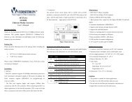
7. Configure from Console Port<br />
(1) Setup Hardware and Software for Configuration<br />
Hardware setup<br />
Connect from the console <strong>port</strong> of the <strong>Switch</strong> to COM <strong>port</strong> of PC with the console cable.<br />
Software setup<br />
1. PC is running MS Windows.<br />
2. Start -> Program -> Accessory -> Terminal. Execute "Hypertrm" program. If you cannot<br />
find the Terminal program, please install it from your MS Windows installation disk.<br />
3. If the connection file has been created, cancel the new connection request and open the<br />
connection file. If the connection file has not been created, create a new connection<br />
named "SW<strong>16</strong>" -> Select COM <strong>port</strong> of PC -> Set COM <strong>port</strong> parameters as "Baud Rate:<br />
9600, Data Bits: 8, Parity Check: None, Stop Bit: 1, Flow Control: None". Then OK.<br />
4. Power on the <strong>Switch</strong> and the setup console will appear as follow.<br />
5. The default password is "1234" (you can change it in the console setting). The main<br />
screen will appear if the password is correct.<br />
[Notes:] If you can not get the console screen, please reboot the switch or close the terminal<br />
program and start again.<br />
8 www.versitron.com
(2) Configure Connection Ports of the <strong>Switch</strong><br />
1. Users can enable/disable auto-negotiation, flow control and auto-MDIX functions of the<br />
connection <strong>port</strong>s with this function. If auto-negotiation is disabled, users can set the<br />
connection speed, full/half duplex of the connection <strong>port</strong>s. The default setting is autonegotiation<br />
enable.<br />
2. Follow the direction in the setup menu to setup the configuration of the connection <strong>port</strong>s.<br />
(3) Setup VLAN Groups of the <strong>Switch</strong><br />
1. Select VLAN setup function in the main menu as follows:<br />
Note: Before starting to set VLAN, the trunking function will be disabled first. After<br />
VLAN setup is completed, you may set the trunking function if you need trunking<br />
connection on the switch.<br />
2. You can select the quick setup item for Concentration VLAN or the other VLAN<br />
configuration. If you want to use concentration VLAN, use function 1 and select which<br />
<strong>port</strong> is the common <strong>port</strong> for the concentration VLAN. The software will create<br />
concentration VLAN configuration automatically. (You may refer to Section 6.1 for<br />
concentration VLAN configuration.)<br />
3. If you want to configure VLAN by yourself, use function 2 to setup VLAN group and<br />
PVID of <strong>port</strong>s. Use "VLAN Setup" to create VLAN groups first. Then set PVID and<br />
tag/untagged of <strong>port</strong>s.<br />
9 www.versitron.com
4. If you want to configure VLAN by yourself, use function 2 to setup VLAN group and<br />
PVID of <strong>port</strong>s. Use "VLAN Setup" to create VLAN groups first. Then set PVID and<br />
tag/untagged of <strong>port</strong>s.<br />
m: modify setting of VLAN group. Select the VLAN group first and the connection <strong>port</strong>.<br />
Then select the operation - add or remove the <strong>port</strong> to/from the VLAN.<br />
a: add <strong>port</strong>s to VLAN. Select the VLAN group first and then select the <strong>port</strong>s to add to<br />
the VLAN group.<br />
d: delete VLAN group. This function will delete one VLAN group.<br />
q: quit from this function. "Save & Update (Y/N)" message will be prompted to ask you<br />
if you want to save and update to this new setting.<br />
5. Then, we use "PVID Setup" function to set the PVID of <strong>port</strong>s.<br />
After you complete the VLAN groups setup, you have to set the PVID of <strong>port</strong>s to the<br />
VLAN ID of their VLAN group. If <strong>port</strong> overlapping happens, please assign the PVID of<br />
the overlapped <strong>port</strong> to the VLAN ID that it will use for packet transmitting VLAN<br />
grouping.<br />
If tagged packets, VLAN ID is in the tag of the packets. If untagged packets, the switch<br />
will assign PVID to the packet as its VLAN ID. And the switch will check the VLAN<br />
group setting with the VLAN ID. If they belong to the same VLAN, the packets will be<br />
forwarded. If they belong to different VLANs, the packets will be filtered out.<br />
Note: Because this switch sup<strong>port</strong>s VLAN ID 0~15 only, the switch will use bit 0~3 of the<br />
VLAN ID as its VLAN ID if the VLAN ID in the tagged packets are larger than 15.<br />
<strong>10</strong> www.versitron.com
5. You can use command "m" to set <strong>port</strong>s to tag or untagged and set PVID of <strong>port</strong>s. The<br />
output packets from a tag <strong>port</strong> will always be tagged packets. If untagged packets, tag<br />
will be added before these packets are transmitted. And the output packets from<br />
untagged <strong>port</strong> will always be untagged packets. If tagged packets, the tag will be<br />
removed before these packets are transmitted.<br />
The tag or untagged setting depends on your applications in the network. If you are not<br />
sure about your network application, you may set all of them to untagged because many<br />
old network devices do not sup<strong>port</strong> long Ethernet packets with a tag (tag is another 4<br />
bytes added to normal Ethernet packets).<br />
Notes: Data will only be forwarded to <strong>port</strong>s in the same VLAN group. Data will not be<br />
forwarded to <strong>port</strong>s in different VLAN groups, as if they were not connected together. The<br />
factory default setting of the switch is all <strong>port</strong>s are in the same VLAN group.<br />
(4) Setup Trunking Connection of the <strong>Switch</strong><br />
1. Enter the Trunk setup function in the main menu as follows:<br />
2. This switch sup<strong>port</strong>s two trunks and two <strong>port</strong>s per trunk maximum. You can select the<br />
trunk and enable or disable it in this setup function.<br />
Notes: Before you enable the trunk, please check the VLAN setting of the <strong>port</strong>s used<br />
for the trunk. They must belong to the same VLAN group and have the same PVID<br />
and tag/untagged setting. If they are different on some items, please make them<br />
have the same configuration first.<br />
(5) Change Password<br />
1. You can change password with this function.<br />
11 www.versitron.com
(6) Advanced Setup<br />
There are three advanced functions for switch you can setup here:<br />
1. Port Locking<br />
In the Port Locking function, you can allow only one user to use the network connection<br />
of some <strong>port</strong> through the switch. There could be two different lock operations for the<br />
switch.<br />
Static Lock: If the "<strong>Switch</strong> Aging" function of the switch in "Broadcast Storm Filter"<br />
setup is set to disable, only the user that the switch learns firstly on that <strong>port</strong> can use this<br />
connection <strong>port</strong> even if the user turns OFF his PC.<br />
Dynamic Lock: If the "<strong>Switch</strong> Aging" setting is enable, another user with other Mac ID<br />
could be the "only-one" user for the <strong>port</strong> after last user is OFF and his MAC ID is aged<br />
out.<br />
2. Broadcast Storm Filter<br />
You can enable/disable the aging and broadcast storm filtering functions of the switch<br />
from this function.<br />
If the broadcast storm filtering function is enable, the broadcast packets over the rising<br />
threshold within 50ms will be discarded. You can set three threshold levels (per <strong>port</strong>) for<br />
broadcast storm.<br />
1: <strong>10</strong>% for all <strong>10</strong>0TX, 1% for not all <strong>10</strong>0TX<br />
2: 20% for all <strong>10</strong>0TX, 2% for not all <strong>10</strong>0TX<br />
3: 40% for all <strong>10</strong>0TX, 4% for not all <strong>10</strong>0TX<br />
12 www.versitron.com
3. CoS (Class of Service)<br />
There are 4 transmit queues per <strong>port</strong> in the switch to sup<strong>port</strong> CoS function and you<br />
configure the CoS function of the switch with this function.<br />
1. Global<br />
Because this switch can perform CoS function with Port-base, VLAN-base or TOSbase,<br />
you can configure it with this function.<br />
TOS Over VLAN priority: If enabled, the priority information in TOS will be<br />
processed first then priority information in VLAN tag. If disabled, the priority<br />
information in VLAN tag will be processed first.<br />
Port-Base Priority: If enabled, all the packets received from this <strong>port</strong> will be always<br />
sent with the assigned priority and the priority information in VLAN tag and TOS<br />
will be ignored.<br />
Port Priority: Assign the transmit priority of packets received from the <strong>port</strong> if "Port-<br />
Base Priority" is enabled.<br />
2. VLAN/TOS Priority Map<br />
You can map the priority value in VLAN/TOS to the four transmit queues with this<br />
function.<br />
There could be eight different priority values in VLAN tag and TOS and these values<br />
will be mapped to the four transmit queues in each <strong>port</strong> of the switch. You can<br />
arrange the mapping here.<br />
13 www.versitron.com
(7) Restore Default Setup<br />
You can restore the configuration to the default setting with this function.<br />
(8) Exit<br />
You can exit this setup interface with this function and it will go back to the login screen.<br />
14 www.versitron.com
A. Product Specifications<br />
Access Method<br />
CSMA/CD, <strong>10</strong> Mbps or <strong>10</strong>0 Mbps<br />
Standards Conformance IEEE 802.3 <strong>10</strong>BASE-T,<br />
IEEE 802.3u <strong>10</strong>0BASETX/FX<br />
Communication Rate <strong>10</strong>/<strong>10</strong>0Mbps on RJ-45 <strong>port</strong>s, <strong>10</strong>0Mbps on FX <strong>port</strong><br />
Communication Mode Full / Half duplex<br />
Media Sup<strong>port</strong>ed<br />
<strong>10</strong>BASE-T - <strong>10</strong>0 Ohm Category 3,4,5 twisted-pair<br />
<strong>10</strong>0BASE-TX - <strong>10</strong>0 Ohm Category 5 twisted-pair<br />
<strong>10</strong>0BASE-FX - fiber optic cable<br />
Indicator Panel<br />
LEDs for Power (each unit),<br />
Link/Act, FDX/Col. (each <strong>port</strong>)<br />
Number of Ports<br />
<strong>16</strong>* RJ45 TX <strong>port</strong>s, 1* module <strong>port</strong><br />
1* RJ45 console <strong>port</strong><br />
MDI-X/MDI Selection Auto detect<br />
Dimensions<br />
<strong>16</strong>.93 x 4.13 x 1.73 in. (430 x <strong>10</strong>5 x 44 mm.)<br />
Certification<br />
CE Mark<br />
Emissions<br />
FCC Class A<br />
Immunity IEC <strong>10</strong>00-4-2/3/4<br />
Power Consumption 15Watts max.<br />
Input Power<br />
Full range: <strong>10</strong>0 to 240V, 50 to 60 Hz<br />
Temperature<br />
Standard Operating: 0 to 50 0 C<br />
Storage: -40 to 70 0 C<br />
Humidity<br />
5% to 95% (Non-condensing)<br />
Network Bridging Function<br />
<strong>Switch</strong>ing Method<br />
Address Table<br />
Filtering/Forwarding Rate<br />
CoS<br />
VLAN<br />
Trunking<br />
Filtering, forwarding and learning<br />
Store-and-forward<br />
2K entries<br />
Line speed<br />
4 queues per <strong>port</strong><br />
<strong>16</strong> VLAN groups max.<br />
2 <strong>port</strong>s/trunk max., 2 trunks are allowed<br />
15 www.versitron.com
B. Cable Specification<br />
Two different types of cable could be used on this <strong>16</strong>-<strong>port</strong> <strong>Switch</strong>:<br />
• Straight through cable<br />
• Cross-over cable<br />
• Fiber Optic cable if this <strong>16</strong>-<strong>port</strong> <strong>Switch</strong> has a FX <strong>port</strong><br />
Cable Schematics<br />
Straight-Through Cable<br />
Hub / <strong>Switch</strong> side<br />
Adapter side<br />
Pin # Pair # Pin # Pair #<br />
1 RX+ White-Green ---------------- 1 RX+ White-Green<br />
2 RX- Green ---------------- 2 RX- Green<br />
3 TX+ White-Orange ---------------- 3 TX+ White-Orange<br />
4 Not Used Blue ---------------- 4 Not Used Blue<br />
5 Not Used White-Blue ---------------- 5 Not Used White-Blue<br />
6 TX- Orange ---------------- 6 TX- Orange<br />
7 Not Used White-Brown ---------------- 7 Not Used White-Brown<br />
8 Not Used Brown ---------------- 8 Not Used Brown<br />
Cross-Over Cable<br />
Hub / <strong>Switch</strong> side<br />
Hub / <strong>Switch</strong> side<br />
Pin # Pair # Pin # Pair #<br />
1 RX+ White-Green ---- ---- 1 RX+ White-Green<br />
2 RX- Green ---- ---- 2 RX- Green<br />
3 TX+ White-Orange ---- ---- 3 TX+ White-Orange<br />
4 Not Used Blue 4 Not Used Blue<br />
5 Not Used White-Blue 5 Not Used White-Blue<br />
6 TX- Orange ---- ---- 6 TX- Orange<br />
7 Not Used White-Brown 7 Not Used White-Brown<br />
8 Not Used Brown 8 Not Used Brown<br />
<strong>16</strong> www.versitron.com
EMI Certification<br />
C. Compliance<br />
FCC Class A Certification (USA)<br />
Warning: This equipment generates, uses, and can radiate radio frequency energy and, if not<br />
installed and used in accordance with the instruction manual, may cause interference to radio<br />
communications. It has been tested and found to comply with the limits for a Class A digital<br />
device pursuant to Subpart B of Part 15 of FCC Rules, which are designed to provide reasonable<br />
protection against such interference when operated in a commercial environment. Operation of<br />
this equipment in a residential area is likely to cause interference, in which case the user, at his<br />
own expense, will be required to take whatever measures are required to correct the interference.<br />
Canada Department of Communications - Class A<br />
This digital apparatus does not exceed the Class A limits for radio noise emissions from digital<br />
apparatus as set out in the interference-causing equipment standard entitled "Digital Apparatus",<br />
ICES-003 of the Department of Communications.<br />
CE Mark Declaration of Conformance for EMI and Safety (EEC)<br />
This is to certify that this product complies with ISO/IEC <strong>Guide</strong> 22 and EN45014.<br />
It conforms to the following specifications:<br />
EMC: EN55022 (1988)/CISPR-22 (1985) class A<br />
EN60555-2 (1995)<br />
class A<br />
EN60555-3<br />
IEC<strong>10</strong>00-4-2 (1995)<br />
4kV CD, 8kV AD<br />
IEC<strong>10</strong>00-4-3 (1995)<br />
3V/m<br />
IEC<strong>10</strong>00-4-4 (1995)<br />
1kV - (power line), 0.5kV - (signal line)<br />
This product complies with the requirements of the Low Voltage Directive 73/23/EEC and the<br />
EMC Directive 89/336/EEC.<br />
Warning! Do not plug a phone jack connector in the RJ-45 <strong>port</strong>. This may damage this device.<br />
17 www.versitron.com