Assembly instructions confocalDT 2471 (PDF, 1.78 ... - Micro-Epsilon
Assembly instructions confocalDT 2471 (PDF, 1.78 ... - Micro-Epsilon
Assembly instructions confocalDT 2471 (PDF, 1.78 ... - Micro-Epsilon

Create successful ePaper yourself
Turn your PDF publications into a flip-book with our unique Google optimized e-Paper software.
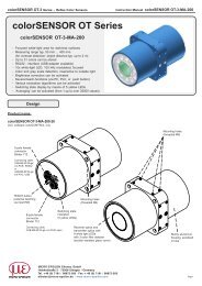
Functions<br />
--<br />
Distance measurement against reflecting (mirroring and diffuse) surfaces<br />
--<br />
Thickness measurement of transparent objects<br />
--<br />
Triggering, synchronization and further functions<br />
--<br />
Ethernet- or EtherCAT interface<br />
--<br />
Measuring rate up to 70 kHz<br />
<strong>Assembly</strong> Instructions<br />
<strong>confocalDT</strong> <strong>2471</strong><br />
Warnings<br />
Do not open the external light source (IFX<strong>2471</strong>), connect the power supply in accordance to the<br />
safety regulations for electrical equipment. The power supply may not exceed the specified limits.<br />
> > Danger of injury, damage to or destruction of the system<br />
Protect the optical fiber ends from dirt and contamination, protect the cables from damage.<br />
> > Failure of the measurement device<br />
Do not cover the ventilation slots on the top and bottom of the external light source.<br />
> > Damage to external light source, or light source switches off automatically.<br />
Avoid shock and vibration to the controller, sensor or the external light source.<br />
> > Damage to or destruction of the system<br />
Notes on CE Identification<br />
The following applies to the <strong>confocalDT</strong> <strong>2471</strong> system: EMC regulation 2004/108/EC<br />
The system satisfies the requirements of the standards<br />
--<br />
EN 61000-6-3 / EN 61326-1 (Class B) Interference emission<br />
--<br />
EN 61000-6-2 / EN 61326-1 Immunity to interference<br />
Proper Environment<br />
--<br />
Protection class IP 40 (Controller, xenon light source)<br />
IP 64 (Sensor)<br />
--<br />
Operating temperature<br />
Sensor, Controller: 5 ... +50 °C (+41 ... +122 °F)<br />
--<br />
Storage temperature: -20 ... 70 °C (-4 ...+158 °F)<br />
For further informations about the system read the instruction manual. You will find this online at:<br />
www.micro-epsilon.com/download/manuals/man--<strong>confocalDT</strong>-2451-<strong>2471</strong>--en.pdf or on the delivered<br />
CD.<br />
<strong>Assembly</strong><br />
Place the controller IFC<strong>2471</strong> on a level surface, or install it at a location of your choice (e.g. in a<br />
switch cabinet) using a DIN EN 60715 mounting rail (DIN rail TS35).<br />
To remove, push the controller upwards, and pull it forwards.<br />
i<br />
When attaching the controller, ensure that no connections, operating or display elements are<br />
covered.<br />
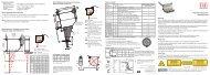
Dimensional Drawing IFC<strong>2471</strong><br />
120 (4.87)<br />
218 (8.58)<br />
(Feets can be removed)<br />
Sensor Cable, Optic Fiber<br />
appr. 63 (2.48)<br />
DIN rail<br />
fastener<br />
76.2 (3.00)<br />
81.2 (3.20)<br />
LWL sensor<br />
cable<br />
R30<br />
Other cables:<br />
less space<br />
ca. 75 (2.95)<br />
Do not shorten or lengthen the optical fibers. A damaged sensor cable cannot be repaired, but<br />
replaced only.<br />
Avoid any contamination of the connector, mechanical stress, bending the cable.<br />
Minimum bending radius: 30 mm fixed, 40 mm permanent flexible<br />
i<br />
Mounting Sensor, Installation Bracket<br />
The sensors of series IFS240x are optical sensors for measurements in micrometer accuracy.<br />
Please ensure careful handling<br />
during installation and operation!<br />
i<br />
Use an installation bracket to<br />
mount IFS 2402/2403/2405 sensors.<br />
MA2400<br />
MA2402<br />
MA2403<br />
MA2405<br />
IFS2402-x<br />
IFS2403-x<br />
IFS2405-x<br />
•<br />
•<br />
•<br />
• MICRO-EPSILON MESSTECHNIK<br />
GmbH & Co. KG<br />
Königbacher Str. 15 · 94496 Ortenburg<br />
www.micro-epsilon.com<br />
*X9771238.01-A04*<br />
X9771238.01-A041084MSC<br />
Ethernet, EtherCAT<br />
Potential isolated RJ 45 standard connector for connecting the controller IFC<strong>2471</strong> to an Ethernet<br />
network (PC) or the EtherCAT bus system.<br />
The controller is connected with a PC or generally with a network via the Ethernet interface. The<br />
internal websites can be accessed in the controller with a web browser and so the controller can<br />
be operated.<br />
Encoder Inputs<br />
Three encoders can be connected simultaneously and powered with 5 V<br />
using the 15-pin HD-sub connector.<br />
Each encoder provides A, B and N signals (zero pulse, reference, index).<br />
The maximum pulse frequency is 1MHz.<br />
Values for A, B, N: TTL level<br />
2.4 V ≤ High ≤ 5 V<br />
0 V ≤ Low ≤ 0.5 V<br />
Reference value: GND<br />
Encoder supply 5 V: 5 V each, max. 150 mA<br />
Encoder<br />
Encoder Pin Signal Encoder Pin Signal Encoder Pin Signal<br />
5 A1<br />
4 A2<br />
3 A3<br />
15 B1 14 B2 13 B3<br />
1<br />
10 N1 9 N2 8 N3<br />
2<br />
3<br />
1 GND1 6 GND2 11 GND3<br />
2 5V-1 7 5V-2 12 5V-3<br />
Cover Screen Cover Screen Cover Screen<br />
Analog Output<br />
Analog outputs can either be used for distance or thickness measurements. Only one type of<br />
measurement can be transmitted at any given time.<br />
The analog output has a resolution of 16 bit. Either the voltage or the current output on the controller<br />
can be used at any given time.<br />
11.4 V<br />
10 V<br />
Analog<br />
output<br />
0 V<br />
LED “Range”<br />
Error<br />
Standard characteristic<br />
Start of measuring<br />
range<br />
Target<br />
Target in measuring range<br />
End of measuring<br />
range<br />
Error<br />
Screw Terminals<br />
Pin Description Comments<br />
U out Voltage output<br />
0 ... 5 V; 0 ... 10 V; -5 ... +5 V;<br />
-10 ... +10 V; R i<br />
appr. 30 Ohm<br />
I out Current output 4 ... 20 mA; R L<br />
≤ 500 Ohm<br />
GND U/I<br />
SyncIn/<br />
TrigIn<br />
SyncOut<br />
Error 1 / 2<br />
GND<br />
HLL<br />
Ground analog<br />
output<br />
Input synchronization<br />
or triggering<br />
Synchronous<br />
output<br />
Error outputs<br />
Ground potentials<br />
Switching logic<br />
level of digital I/O<br />
Galvanically isolated from<br />
supply<br />
Low logic level (LLL) or high<br />
logic level (HLL), switchable<br />
via bridge „HLL“.<br />
All GND are connected to<br />
each other and to the operating<br />
voltage ground.<br />
open: LLL (Low logic level);<br />
bridge: HLL (High logic level)<br />
24 VDC Operating voltage ± 15 %, I<br />
max < 1 A<br />
GND<br />
Operating voltage<br />
ground<br />
GND is galvanically connected<br />
to GND of switching<br />
outputs, synchronization and<br />
encoder input.<br />
Analog Out<br />
U out<br />
GND U<br />
Shield<br />
I out<br />
GND I<br />
Digital I/O<br />
SyncIn / TrigIn<br />
GND<br />
Shield<br />
SyncOut<br />
GND<br />
Error 1<br />
GND<br />
Shield<br />
Error 2<br />
GND<br />
Power<br />
24 VDC<br />
GND<br />
Shield<br />
Shields to respective output/input, connector<br />
Shield<br />
housing<br />
The plug-in screw terminals are designed for a conductor cross-section of 0.14 mm² up to<br />
1.5 mm². The screw terminals are mounted with two screws on the controller and can be removed<br />
for the wiring or a quick controller change.<br />
LEDs<br />
Status Off No error If the EtherCAT interface is<br />
active, then the meaning of the<br />
Red flashing Processing error<br />
Status-LED is conform with the<br />
Red<br />
Error during synchronization<br />
EtherCAT guidelines.<br />
Intensity<br />
Range<br />
Red flashing<br />
Red<br />
Yellow<br />
Green<br />
Red flashing<br />
Red<br />
Yellow<br />
Green<br />
Dark signal acquisition in<br />
progress<br />
Signal in saturation<br />
Signal too low<br />
Signal ok<br />
Dark signal acquisition in<br />
progress<br />
No target or out of range<br />
Midrange<br />
Target in the measuring<br />
range<br />
HLL
Life time / hours<br />
Max life time reached<br />
Overheat<br />
Power On<br />
Quick Guide<br />
Structure of the Components<br />
--<br />
Controller, Sensor and clamp<br />
--<br />
Power supply, Laptop / PC + USB -> Ethernet adapter + Ethernet cable<br />
--<br />
Xenon light source IFX<strong>2471</strong><br />
Connect the components together and mount the sensor into the clamp.<br />
The start screen of the controller<br />
software should be displayed in the<br />
web browser now.<br />
The LED range on the front side of the controller shows the position of the target to the sensor.<br />
Check Video Signal<br />
Red flashing<br />
Red<br />
Yellow<br />
Green<br />
Dark signal acquisition in progress<br />
No target, or target outside the measuring range<br />
Target near the midrange<br />
Target within the measuring range<br />
Thickness Measurement<br />
Go to the menu Preferences > Measurement program. Select the thickness measurement<br />
program.<br />
Differing from the previous steps the target material is to considered when measuring the thickness.<br />
Select a material from the database.<br />
Run<br />
X1<br />
X2<br />
BECKHOFF EK1122<br />
Patch cable<br />
Intensity >max<br />
Intensity Measurement program.<br />
Select displace Measurement as measurement program to be performed.<br />
Select Sensor<br />
Go to the menu Preferences > Sensor.<br />
Select a sensor from the list. Confirm with Submit.<br />
Perform Dark Reference<br />
This adjustment is necessary after each sensor change; warm-up time controller about 30 min.<br />
Cover the sensor with a piece of dark paper and press the Dark Reference button on controller<br />
or the Start dark reference button on the Dark reference web page.<br />
For dark referencing, no object must be within the measuring range, and no ambient or external<br />
light must reach the sensor. Duration about 20 s. Alternatively, you can also perform the dark reference<br />
in the Video signal menu.<br />
Place Target<br />
Place the target in the midrange.<br />
100 %<br />
Signal<br />
50<br />
0<br />
Displacement<br />
SMR = Start of measuring range<br />
SMR MMR EMR<br />
MMR = Midrange<br />
Target<br />
EMR = End of measuring range<br />
Go to the Video signal menu and adjust any settings on the exposure mode, the measuring<br />
rate and the detection threshold if applicable.<br />
The recognition threshold should be as low as possible and preferably not be changed.<br />
Menu Measurement<br />
1<br />
Login<br />
Home Preferences Measurement Video signal Help/Info<br />
Measurement program<br />
Sensor<br />
Exposure mode/measuring rate<br />
Detection threshold<br />
Averaging/error handling<br />
Zeroing/mastering<br />
Material database<br />
Digital interfaces<br />
Switching outputs<br />
Analog output<br />
Output- data rate<br />
Save Settings<br />
Encoder inputs<br />
Trigger mode<br />
Synchronization<br />
Preferences > Material database<br />
Material database<br />
Material name Description<br />
Vacuum, Air Vacuum; air 1.000000 1.000000 1.000000<br />
Quartz glass,<br />
Fused Silica 1.463126 1.458464 1.456367<br />
silica<br />
PMMA Acrylic glass 1.497761 1.491756 1.489200<br />
PMMI<br />
Polymethacryl<br />
methylimid,<br />
a plastic<br />
1.534000 1.534000 1.534000<br />
PS<br />
Polystyrol,<br />
a plastic<br />
1.604079 1.590481 1.584949<br />
PC<br />
Polycarbonat,<br />
a plastic<br />
1.599439 1.585470 1.579864<br />
<strong>confocalDT</strong> <strong>2471</strong><br />
Refractive index Refractive index<br />
n F<br />
at 486 nm n D at<br />
587 nm<br />
Refractive index<br />
n C at<br />
656 nm<br />
Abbe value n d<br />
BK7 Crown glass 1.522380 1.516800 1.514320<br />
Acrylic<br />
Acrylic rosin, e.g<br />
1.497828 1.491668 1.488938<br />
adhesive, lacquer<br />
Save Setup<br />
The current settings can be saved in the controller in one setup. Otherwise the settings are lost<br />
when switching off.<br />
Login<br />
Home Preferences Measurement Video signal Help/Info<br />
Measurement program<br />
Sensor<br />
Exposure mode/measuring rate<br />
Detection threshold<br />
Averaging/error handling<br />
Zeroing/mastering<br />
Material database<br />
Digital interfaces<br />
Switching outputs<br />
Analog output<br />
Output-data rate<br />
Encoder inputs<br />
Trigger mode<br />
Synchronization<br />
Settings loading/saving<br />
Manage setups on PC<br />
Extras<br />
Preferences > Settings loading / saving<br />
Settings loading / saving<br />
Status: OK<br />
Setup no.:<br />
Maintaining interface settings:<br />
1<br />
<strong>confocalDT</strong> <strong>2471</strong><br />
Activate<br />
Save setup<br />
Save Setup<br />
Application flow saving:<br />
Store settings in the controller permanently (otherwise the settings will be lost when turning off). Various<br />
parameter sets can be stored. When turning on, the last stored parameter is loaded.<br />
Select a setup and click on the Save setup button.<br />
When switching on, the parameter set (setup) is loaded, which is saved in the controller at last.<br />
Maintain interface settings<br />
If the checkbox is activated, the settings for language, password, analog output and network will kept.<br />
Activate<br />
By clicking this button, the selected setup file is loaded in the controller.<br />
Save setup<br />
Clicking this button saves the settings in the selected setup file.<br />
Manage setups on PC Importing/exporting of setup and material settings between PC and controller.<br />
Select the designated controller from the list.<br />
Click the button Start browser to connect the controller with your default browser.<br />
Sensor<br />
SMR<br />
Measuring range (MR)<br />
MR<br />
= Measuring range<br />
1 It is recommended, to set the scaling manually at first and not to select too fine.