Drilling fluid products for rotary drilling tion - GWE German Water ...
Drilling fluid products for rotary drilling tion - GWE German Water ...
Drilling fluid products for rotary drilling tion - GWE German Water ...

You also want an ePaper? Increase the reach of your titles
YUMPU automatically turns print PDFs into web optimized ePapers that Google loves.
<strong>Drilling</strong> <strong>fluid</strong> <strong>products</strong><br />
<strong>for</strong> <strong>rotary</strong> <strong>drilling</strong>
<strong>Drilling</strong> <strong>fluid</strong> in<br />
well construc<strong>tion</strong><br />
With the introduc<strong>tion</strong> of mobile, hydraulically driven<br />
flush <strong>drilling</strong> equipment at the end of the 1950s, circula<strong>tion</strong><br />
<strong>fluid</strong>s have become increasingly important in<br />
well construc<strong>tion</strong>. Through the controlled use of<br />
agents in water-based <strong>drilling</strong> <strong>fluid</strong>s, it has been possible<br />
to satisfy the continuously increasing demands<br />
of clients <strong>for</strong> deeper, larger and more efficient wells.<br />
Modern <strong>drilling</strong> <strong>fluid</strong>s becoming state-of-the-art technique<br />
enables <strong>for</strong> the fast <strong>drilling</strong> of uncased boreho-<br />
les <strong>for</strong> water supply, monitoring purposes, geothermal<br />
applica<strong>tion</strong>s and mineral explora<strong>tion</strong>.. The technical<br />
and economic benefits in comparison to the dry hole<br />
method are indisputable.<br />
As a leading manufacturer and supplier of well construc<strong>tion</strong><br />
materials, SBF-Hagusta GmbH provides a<br />
complete range of bentonites, protective colloid polymers,<br />
weighting materials and chemicals <strong>for</strong> the crea<strong>tion</strong><br />
of up-to-date circula<strong>tion</strong> systems.
1.0 Defini<strong>tion</strong>s<br />
The development of <strong>drilling</strong> <strong>fluid</strong> technology began<br />
with the inven<strong>tion</strong> of the <strong>rotary</strong> <strong>drilling</strong> process which<br />
was patented by Robert Beart in 1845. <strong>Water</strong> was<br />
originally used as the <strong>drilling</strong> <strong>fluid</strong> which, as <strong>drilling</strong><br />
progressed, became gradually infused with cuttings,<br />
<strong>for</strong>ming a sludge known as <strong>drilling</strong> mud. Experience<br />
showed that <strong>drilling</strong> mud, particularly after sinking<br />
through swelling clay particles, demonstrated better<br />
properties than pure circula<strong>tion</strong> successfully water.<br />
Subsequently, clay-water suspensions were used<br />
instead of pure water. In 1921, <strong>drilling</strong> <strong>fluid</strong>s with<br />
baryte were introduced <strong>for</strong> the first time in high-pressure<br />
beds. Chemicals and water-soluble polymers<br />
were added to optimise the <strong>drilling</strong> <strong>fluid</strong> characteristics<br />
from 1929 onwards.<br />
Nowadays, semi-complex circula<strong>tion</strong> systems are<br />
available <strong>for</strong> nearly all <strong>drilling</strong> tasks, where the term<br />
ʻ<strong>drilling</strong> <strong>fluid</strong>ʼ describes all circulating liquids and<br />
gases in the borehole that are controlled during the<br />
<strong>drilling</strong> process.<br />
2.0 Func<strong>tion</strong>ally of <strong>Drilling</strong> <strong>fluid</strong>s<br />
<strong>Drilling</strong> <strong>fluid</strong> <strong>products</strong><br />
The applica<strong>tion</strong> of <strong>drilling</strong> <strong>fluid</strong>s encompass the following<br />
areas:<br />
● removal of cuttings from the bottom of the borehole<br />
and settling them at the surface<br />
● supporing and stabilising of the uncased borehole<br />
wall<br />
● balancing high rock as well as bedding pressures<br />
● protecting target <strong>for</strong>ma<strong>tion</strong>s<br />
● cooling and lubricating the drill bit<br />
According to experience, these requirements cannot<br />
be sufficiently fulfilled if only pure water is used as a<br />
circulating <strong>fluid</strong>. The use of water is there<strong>for</strong>e limited<br />
to a few isolated cases, <strong>for</strong> example <strong>drilling</strong> in stable,<br />
low-permeable bedrock.<br />
2.1 Removal of cuttings<br />
The removal of cuttings from the bottom of the hole<br />
to the surface is significantly influenced by 3 factors:<br />
● the uphole-flowrate of the <strong>fluid</strong><br />
● the relative densities of the <strong>fluid</strong> and the cuttings<br />
● the viscosity of the <strong>drilling</strong> <strong>fluid</strong><br />
Particularly in cases where the circula<strong>tion</strong> <strong>fluid</strong> is<br />
pumped down the drill pipe (pressure <strong>drilling</strong>), the<br />
<strong>drilling</strong> equipment (bit, rod diameter, circula<strong>tion</strong> pump)<br />
must be appropriately designed that the ascending<br />
<strong>fluid</strong> reaches flow rates between 0.5 m/s – 1.0 m/s in<br />
the annulus of the borehole.<br />
To achieve these desired uphole velocities, the following<br />
pump rates are recommended:<br />
Minimum pump rate 110 l/min per inch<br />
bit diameter<br />
<strong>Drilling</strong> progress < 4.5 m/h: approx. 130 l/m<br />
per inch bit diameter<br />
<strong>Drilling</strong> progress > 4.5 m/h: approx. 160 l/m<br />
per inch bit diameter<br />
To be avoided: pump rates > 200 l/min per inch bit diameter.<br />
These rates cause turbulent flows which lead to borehole<br />
enlargements and wear of <strong>drilling</strong> tool.<br />
The smaller the difference in density between the<br />
drilled solids (approx. 2.6 kg/l) and the <strong>drilling</strong> <strong>fluid</strong>,<br />
the lower their settling rate. However, it is not recommendable<br />
to increase the density of the <strong>drilling</strong> <strong>fluid</strong><br />
with the aim of improving its carrying capacity as<br />
heavy <strong>fluid</strong>s laden with solids impede <strong>drilling</strong> progress<br />
and raise the risk of the target borehole zones<br />
becoming permanently blocked.<br />
It is much more suitable to use <strong>drilling</strong> <strong>fluid</strong>s having<br />
alow solid content and to enhance their viscosity by<br />
adding special additives (Table 1).<br />
2.2 Borehole stabilisa<strong>tion</strong><br />
Essentially, <strong>for</strong> the uncased borehole to be supported,<br />
the pressure of the <strong>fluid</strong> column must be greater<br />
than the exerted by the groundwater and the <strong>for</strong>ma<strong>tion</strong>.<br />
1
Table 1:<br />
Overview of agents <strong>for</strong> raising carrying capacity/viscosity<br />
A difference in hydrostatic pressure of 2 m<br />
H2O has proven to be sufficient. In addi<strong>tion</strong>,<br />
an impervious zone must <strong>for</strong>m in the<br />
<strong>for</strong>ward <strong>drilling</strong> area so that the <strong>fluid</strong><br />
column pressure can act on the earth and<br />
groundwater pressure, thus preventing<br />
circula<strong>tion</strong> losses.<br />
The filtra<strong>tion</strong> processes that build up the<br />
filter cake on the borehole wall (or an<br />
impervious zone in the <strong>for</strong>ward <strong>drilling</strong><br />
area) differ depending on the pore size of<br />
the lithology encountered:<br />
● The voids (pores) are larger than<br />
the solid particles in the <strong>fluid</strong>.<br />
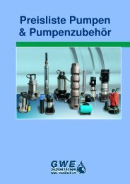
This situa<strong>tion</strong> usually occurs when <strong>drilling</strong><br />
in unconsolidated sediments such as<br />
beds of gravel and sand (see Fig. 1, upper<br />
sec<strong>tion</strong> of borehole with grit/gravel). Particles<br />
in the <strong>drilling</strong> <strong>fluid</strong> (clay particles/bentonite<br />
platelets/long-chained polymer<br />
molecules) <strong>for</strong>m a mesh in the open spaces<br />
of the permeable <strong>for</strong>ma<strong>tion</strong> which<br />
balances the pressures. The water slowly<br />
penetrates through this mesh and a successively<br />
impermeable thin layer is build<br />
up at the borehole wall. This lowpermeability<br />
layer is called „Filter Cake“.<br />
2<br />
Chemical characterisa<strong>tion</strong><br />
Recommended use<br />
active bentonite fresh water <strong>fluid</strong>s<br />
polyanionic CMC* fresh/salt water <strong>fluid</strong>s<br />
industrial CMC* fresh/salt water <strong>fluid</strong>s<br />
polyacrylamide fresh water <strong>fluid</strong>s with low solids content<br />
hydroxyethylcellulose (HEC)<br />
fresh/salt water <strong>fluid</strong>s<br />
Ca2+Mg2+ content > 1500 ppm<br />
* ??????????????????<br />
guar gum bentonite-free fresh water <strong>fluid</strong>s<br />
Fig. 1: Mud infiltra<strong>tion</strong> in an aquifer
● The pores are smaller than the solid particles<br />
in the <strong>fluid</strong>.<br />
The water is squeezed at the borehole wall and slowly<br />
build up a tight barrier through the pores, the solid<br />
particles are deposited (see Fig. 1, lower sec<strong>tion</strong> of<br />
borehole with sandstone/filter cake).<br />
Pore sizes exceeding a certain limit result in losses<br />
of circula<strong>tion</strong>. In such cases, special materials (lost<br />
circula<strong>tion</strong> materials) are applied having a certain<br />
size and shape enabling them to block the open spaces<br />
in the <strong>for</strong>ma<strong>tion</strong> and thereby minimise or stop the<br />
circula<strong>tion</strong> losses. (see Table 2).<br />
Table 2:<br />
Overview of agents <strong>for</strong> stabilising the uncased hole<br />
Characterisa<strong>tion</strong> Recommended use<br />
active bentonite<br />
polyanionic CMC*<br />
industrial CMC*<br />
polyacrylamide<br />
hydroxyethylcellulose<br />
(HEC)<br />
guar gum<br />
In addi<strong>tion</strong> to protecting unconsolidated sediments<br />
from caving in, <strong>drilling</strong> <strong>fluid</strong> has another important<br />
role: to prevent hole instability caused by the hydra<strong>tion</strong><br />
of cutting constituents composed of clay minerals.<br />
Depending on the content of swelling components<br />
in the cuttings, the following may occur:<br />
High concentra<strong>tion</strong> of high swelling constituents.<br />
● constric<strong>tion</strong> of the hole whereby the cuttings often<br />
develop plastic properties<br />
● no caving<br />
pulling overload possible due to<br />
clayey sticking and keyholing of drill string<br />
● rapid thickening of the <strong>drilling</strong> <strong>fluid</strong> due to<br />
loading with cuttings<br />
stabilisa<strong>tion</strong> of sand/gravel beds in fresh water <strong>fluid</strong>s<br />
clay inhibi<strong>tion</strong> in fresh/salt water <strong>fluid</strong>s<br />
clay inhibi<strong>tion</strong> in fresh/salt water <strong>fluid</strong>s<br />
clay inhibi<strong>tion</strong> in fresh/salt water <strong>fluid</strong>s<br />
clay inhibi<strong>tion</strong> in fresh/salt water <strong>fluid</strong>s where Ca2+ /Mg2+ content > 1500 ppm<br />
clay inhibi<strong>tion</strong> in fresh water <strong>fluid</strong>s<br />
For lost circula<strong>tion</strong> materials in all systems, see appended datasheets<br />
* ??????????????????<br />
Viscosity <strong>for</strong>ming effect<br />
Stabilising effect on unconsolidated<br />
sediments<br />
Clay inhibi<strong>tion</strong><br />
Salt stability NaCl/KCI<br />
Salt stability Ca 2+ /Mg 2+<br />
Temperature stability<br />
Biological stability<br />
Overview of agent properties<br />
Bentonite Pure<br />
CMC HV<br />
Industr.<br />
CMC HV<br />
Industr.<br />
CMC LV<br />
HEC<br />
polymer<br />
Key: ++ = very good / + = good / 0 = moderate / - = poor<br />
PAA Polysac<br />
charide<br />
++ ++ ++ – ++ ++ ++<br />
++<br />
–<br />
–<br />
–<br />
+<br />
++<br />
0 0 – 0 – +<br />
++ ++ 0 ++ ++ ++<br />
+ + + + 0 0<br />
– – – ++ – –<br />
+ + + + ++ –<br />
0 0 0 0 + –<br />
3
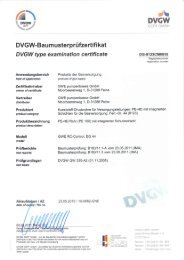
Fig. 2 Clay cuttings in different <strong>drilling</strong> <strong>fluid</strong>s<br />
Dry cuttings be<strong>for</strong>e inser<strong>tion</strong> Cuttings after 24 hours in water<br />
Cuttings after 24 hours in Viscopol <strong>fluid</strong> Cuttings after 24 hours in salinised Viscopol <strong>fluid</strong><br />
Low concentra<strong>tion</strong> of swelling constituents<br />
● enlargement of the hole diameter, caused by the<br />
loosening of the structure of compact cuttings<br />
and their resulting disintegra<strong>tion</strong><br />
● caving which increases with the hydra<strong>tion</strong> of the<br />
<strong>for</strong>ward <strong>drilling</strong> zone<br />
● continuous removal of debris from the instable<br />
cuttings<br />
Clay-inhibiting polymers, if necessary in mixed with<br />
with sodium chloride or potassium chloride, prevent<br />
or at least slow down the progress of the instabilities<br />
described, enabling <strong>for</strong> the <strong>drilling</strong> of geometrically<br />
perfect boreholes even in difficult geological environments<br />
(Fig. 3).<br />
4<br />
2.3 Offsetting high rock<br />
and bed pressures<br />
If high rock and bed pressures are encountered while<br />
<strong>drilling</strong>, a <strong>fluid</strong> column pressure must be created by<br />
raising the specific weight of the <strong>drilling</strong> <strong>fluid</strong> so that<br />
artesian groundwater is prevented from entering the<br />
hole. The weighting must be such to create a pressure<br />
of at least 2 mH 2O.<br />
Materials used <strong>for</strong> weighting are namely ground<br />
chalk (density 2.6 kg/l) <strong>for</strong> <strong>fluid</strong> densities < 1.25 kg/l,<br />
and baryte (density 4.2 kg/l) <strong>for</strong> higher <strong>fluid</strong> densities<br />
(see appended datasheets).
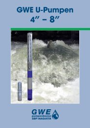
Fig. 3 Calliper logs of two well holes<br />
bit bit<br />
drilled with water or<br />
water + bentonite<br />
max. opening of calliper probe<br />
clay<br />
sand/gravel<br />
brown coal<br />
drilled with water or +<br />
polymer<br />
5
Example of determining the <strong>fluid</strong> density<br />
required in the case of artesian overpressure:<br />
Depth of the artesian inflow: 50 m<br />
<strong>Water</strong> pressure at 50 m: 5,0 bar<br />
Artesian overpressure, ground level: 0,5 bar / 5 mH2O Required <strong>fluid</strong> density to offset the inflow and create<br />
a drop in pressure of 2 mH2O (0.2 bar) at depth.<br />
Fluid density (kg/l) =<br />
Artesian overpressure + required drop in pressure + 1.0<br />
water pressure at inflow depth<br />
Fluid density (kg/l) = 0,5 + 0,2<br />
5,0<br />
+ 1,0<br />
Fluid density (kg/l) =<br />
Fluid weighting:<br />
1,14 kg/l<br />
t/m3 = W3 X (W2 - W1)<br />
W3 - W2<br />
W1 = density of outflow <strong>fluid</strong> kg/l<br />
W2 = required <strong>fluid</strong> density kg/l<br />
W3 = density of weighting material kg/l<br />
It is essential to ensure that weighted <strong>fluid</strong>s have an<br />
increased carrying capacity so that weighting material<br />
does not settle and instead remains evenly distributed<br />
in the suspension. Active bentonite usually<br />
<strong>for</strong>ms the basis of this type of system.<br />
2.4 Protec<strong>tion</strong> of the target aquifer –<br />
<strong>fluid</strong> control<br />
As previously described, the higher hydrostatic pressure<br />
of the <strong>fluid</strong> column compared to the groundwater<br />
pressure in the aquifer causes the <strong>fluid</strong> to penetrate<br />
the <strong>for</strong>ward <strong>drilling</strong> area and enables the <strong>for</strong>ma<strong>tion</strong><br />
of an impervious zone a filter cake. After finalising<br />
the borehole, this filter cake must be removed in<br />
order to enable the groundwater to flow into the well.<br />
This is done by developing the well. To prevent the<br />
building-up of a filter cake which is to thick or which<br />
is penetrating to deep into the <strong>for</strong>ma<strong>tion</strong>, low solids<br />
polymer <strong>fluid</strong>s are applied.<br />
In practice, it is essential that the effectiveness of the<br />
polymers is controlled and thereby safeguarded, particularly<br />
when <strong>drilling</strong> in target <strong>for</strong>ma<strong>tion</strong>. One<br />
method, among others, is to measure the filtra<strong>tion</strong><br />
time (see appendix on <strong>fluid</strong> measuring devices).<br />
6<br />
Guideline <strong>for</strong> protective <strong>fluid</strong> according to DVGW<br />
(<strong>German</strong> Technical and Scientific Associa<strong>tion</strong> <strong>for</strong><br />
Gas and <strong>Water</strong>) in<strong>for</strong>ma<strong>tion</strong> sheet W 116:<br />
Filtra<strong>tion</strong> time: > 1000 s<br />
For holes > 500 m, it is also advisable to check the<br />
filtra<strong>tion</strong> process directly using the API filtra<strong>tion</strong> test.<br />
Guidelines: API filtrate < 10 ml<br />
Filter cake thickness < 1 mm<br />
In order to obtain a protective <strong>drilling</strong> <strong>fluid</strong>, it must<br />
also be ensured that the <strong>fluid</strong> does not become<br />
excessively loaded with fine solids. Experience has<br />
shown that due to their high intrinsic weight, <strong>fluid</strong>s<br />
high in solids penetrate deep into the aquifer and<br />
<strong>for</strong>m thick filter cakes that are difficult to remove.<br />
If borehole condi<strong>tion</strong>s allow, the <strong>fluid</strong> should not<br />
exceed the following threshold value in the screened<br />
borehole zones (DVGW recommenda<strong>tion</strong> W 116):<br />
Recommended value <strong>for</strong> <strong>fluid</strong> density: < 1,10 kg/l<br />
If the <strong>fluid</strong> density exceeds this value, suitable corrective<br />
measures must be taken, including new <strong>fluid</strong><br />
applica<strong>tion</strong>s. Here, it should also be whether the<br />
capacity of the settling tanks/pools has been exhausted<br />
and they need to be emptied. Also, if meeting<br />
the upper limit causes further problems, <strong>for</strong> example<br />
rapid ascent while <strong>drilling</strong>, it may be the case that the<br />
carrying capacity of the <strong>fluid</strong> is too great.<br />
Settling tank system <strong>for</strong> effective control of solids
This can easlily be tested with by measuring the<br />
Marsh time (see appendix on <strong>fluid</strong> measuring devices):<br />
Recommended values:<br />
Funnel viscosity: AZ 38 - 45 s<br />
Funnel emptying time RAZ 28 - 35 s<br />
Adhering to the recommenda<strong>tion</strong>s given above will<br />
result in <strong>drilling</strong> <strong>fluid</strong>s having a sufficient carrying<br />
capacity so that the solids are transported to the surface<br />
and are in the settling areas of the <strong>fluid</strong> tanks.<br />
Without addi<strong>tion</strong>al equipment to control solids (jigging<br />
screen/desander/desilter/mud cleaner), higher<br />
viscosities cause rapid loading with the negative<br />
results described.<br />
Fluid parameters and details of the quantity and type<br />
of agents/water quantities used should be regularly<br />
measured during <strong>drilling</strong> and recorded on appropriate<br />
<strong>for</strong>ms (see appended data checking sheet), not<br />
least as a proof of the quality of services rendered.<br />
3.0 Fluid <strong>for</strong>mula<strong>tion</strong>s<br />
The selec<strong>tion</strong> of the agent is normally determined by<br />
the following factors:<br />
● stability of the rock<br />
● permeability of the rock<br />
● pressure ratios in the rock<br />
● <strong>drilling</strong> method<br />
The use of additive-free water as a circulating <strong>fluid</strong> is<br />
limited to a few isolated cases, <strong>for</strong> example <strong>drilling</strong> in<br />
stable, low-permeable bedrock. If it would be applied<br />
in the case of unconsolidated sands/gravels, the<br />
borehole would not be adequately stable. Equally,<br />
water or pure bentonite <strong>fluid</strong>s only have limited use in<br />
clayey, cohesive sediments. Due to their inadequate<br />
inhibiting properties and high filtra<strong>tion</strong> times, solids<br />
normally accumulate quickly and the clay minerals<br />
present start to swell which causes constric<strong>tion</strong> of the<br />
hole or erosion through caving. Furthermore, the<br />
pores in the aquifer are clogged by cutting substances,<br />
such as sand, clay and silt, in a way that is greater<br />
and more permanent than had the correctly<br />
dosed additives been applied.<br />
When <strong>drilling</strong> in primarily clay sediments it is recommended<br />
that PAA or CMC polymer are used as the<br />
sole additives. In this case, the use of bentonite is<br />
not required as the small quantities of clay cuttings in<br />
the <strong>fluid</strong> will disperse and, in conjunc<strong>tion</strong> with the<br />
polymer, <strong>for</strong>m a tight, thin filter cake.<br />
3.1 Fluid <strong>for</strong>mula<strong>tion</strong> when <strong>drilling</strong><br />
in primarily clay sediments<br />
1 m 3 water<br />
+ 2 kg pure CMC<br />
or + 6 kg industrial CMC<br />
or + 2 kg high-viscosity PAA<br />
A bentonite/polymer <strong>fluid</strong> should be used in interbeds<br />
of sand/gravel/clay, particularly if grits and gravels<br />
are present towards the surface. Bentonite is usually<br />
used <strong>for</strong> the initial applica<strong>tion</strong> of the <strong>fluid</strong> and later the<br />
volume is increased with solid-free polymer solu<strong>tion</strong>,<br />
as clay cuttings also remain in the <strong>fluid</strong> even when<br />
cohesive sediments are encountered.<br />
Foam circula<strong>tion</strong> <strong>for</strong> down-hole hammer <strong>drilling</strong> in bedrock.<br />
7
3.2 Fluid <strong>for</strong>mula<strong>tion</strong> – initial applica<strong>tion</strong><br />
if <strong>drilling</strong> in interbeds of<br />
sand/gravel/clay<br />
1 m 3 water<br />
+ 20 kg bentonite<br />
(left to pre-soak <strong>for</strong> min. 1 h)<br />
+ 1,5 kg pure CMC HV<br />
or + 4,0 kg industrial CMC HV<br />
If artesian water is encountered, bentonite-polymer<br />
<strong>fluid</strong>s are used which are weighted with ground chalk<br />
until the required weighting is achieved (see table in<br />
appendix 3). If the <strong>fluid</strong> density required to balance<br />
the groundwater pressure rises over 1.25 kg/l, baryte<br />
should be applied to achieve further weighting.<br />
3.3 Formula<strong>tion</strong> <strong>for</strong> weighted <strong>fluid</strong>s<br />
1 m 3 water<br />
+ 20 kg bentonite<br />
(left to pre-soak <strong>for</strong> min. 1 h)<br />
+ 1,5 kg pure CMC HV<br />
or + 4,0 kg industrial CMC HV<br />
+ x kg ground chalk<br />
or + x kg baryte with density<br />
upwards from 1.25 kg/l<br />
In this special case, this mixture is also used to increase<br />
volume.<br />
Volume increases<br />
In order to regulate the viscosity of the <strong>fluid</strong> or to<br />
reduce the content of solids in the <strong>fluid</strong> (= density)<br />
the total <strong>fluid</strong> volume needs to be increased. This<br />
should be done by adding pure polymer <strong>fluid</strong>s to the<br />
original mixture. In cases of <strong>drilling</strong> in sand/gravel<br />
<strong>for</strong>ma<strong>tion</strong>s, small propor<strong>tion</strong>s of bentonite should be<br />
added. An excep<strong>tion</strong> of this procedure are weighted<br />
<strong>fluid</strong>s.<br />
3.4 Formula<strong>tion</strong> <strong>for</strong> volume increase<br />
1 m 3 water<br />
+ 0-20 kg bentonite<br />
(left to pre-soak <strong>for</strong> min. 1 h)<br />
+ 1-2 kg pure CMC HV<br />
or + 3-6 kg industrial CMC HV<br />
depending on viscosity<br />
8<br />
Injector <strong>for</strong> mixing polymer <strong>fluid</strong>s<br />
With regard to the sequence in which <strong>products</strong> are<br />
mixed, it is essential that bentonite is always dispersed<br />
first in polymer-free water. There must be a minimum<br />
swelling time of 1 h be<strong>for</strong>e the polymers can be<br />
added.<br />
Injectors are used to mix the <strong>products</strong> to produce a<br />
free of lumps <strong>fluid</strong>. These injectors can be driven by<br />
the <strong>fluid</strong> pump which is present at the <strong>drilling</strong> site<br />
(see above). Alternatively, smaller polymer quantities<br />
can be interspersed at a turbulent loca<strong>tion</strong> in the <strong>fluid</strong><br />
circuit above ground.<br />
Prakla universal <strong>drilling</strong> equipment with settling tank system
4.0 Testing <strong>drilling</strong> <strong>fluid</strong>s<br />
Marsh funnel <strong>for</strong> determining the carrying capacity<br />
of <strong>drilling</strong> <strong>fluid</strong>s<br />
● Seal the bottom end of the funnel and fill with <strong>fluid</strong><br />
through the screen until the level touches the bottom<br />
side of the screen (1500 ml).<br />
● Release the lower opening and use a stop watch to<br />
determine the time required <strong>for</strong> the outflow of 1000<br />
ml of <strong>fluid</strong>. This time period is called „Funnel Viscosity“.<br />
● Then measure the time the remaining 500 ml of<br />
<strong>fluid</strong> needs to flow out of the funnel. This time period<br />
is called „Funnel Emptying Time“.<br />
Guidelines: funnel viscosity 38 – 45 s<br />
funnel emptying time 28 – 35 s<br />
Ring device <strong>for</strong> measuring filtra<strong>tion</strong> time<br />
● Place a filter pape on the base.<br />
● Posi<strong>tion</strong> the metal ring centrally on the filter paper.<br />
● Fill the conical ring opening with the <strong>drilling</strong> <strong>fluid</strong> to<br />
be tested.<br />
● Start your stop watch when the first drop touches<br />
the filter paper.<br />
● Measure the time required <strong>for</strong> the whole of the filter<br />
paper completely soaked. This is called „Filtra<strong>tion</strong><br />
Time“.<br />
Recommended value: > 1000 s<br />
Hydrometer/aerometer <strong>for</strong> determining the<br />
relative density of the <strong>drilling</strong> <strong>fluid</strong><br />
● Fill the cup at the bottom end of the hydrometer<br />
with the <strong>fluid</strong> to be tested, and connect it to the hydrometer<br />
without trapping any air.<br />
● Immerse the hydrometer in a tube filled with water.<br />
● Read off the density of the <strong>fluid</strong> from the point at<br />
which the surface of the liquid touches the stem of<br />
the hydrometer. This number gives you the density<br />
of the <strong>fluid</strong> in kg/l.<br />
Recommended value <strong>for</strong> unweighted <strong>fluid</strong>:<br />
< 1,10 kg/l.<br />
Marsh funnel and measuring jug<br />
Ring device with filter paper, stop watch<br />
1 50 mm diameter filter paper, type Schleicher & Schüll<br />
2040a Mud balance and hydrometer
SBF-Hagusta GmbH<br />
Moorbeerenweg 1<br />
D-31228 Peine<br />
<strong>German</strong>y<br />
Telephone +49 (0) 5171 294-0<br />
Fax +49 (0) 5171 294-177<br />
Email: info@gwe-gruppe.de<br />
www.gwe-gruppe.de<br />
Products <strong>for</strong> well construc<strong>tion</strong><br />
312.004.2