26 576
26 576
26 576

Create successful ePaper yourself
Turn your PDF publications into a flip-book with our unique Google optimized e-Paper software.
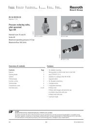
RE <strong>26</strong> <strong>576</strong>/02.03<br />
Replaces: 11.99<br />
Pressure reducing valve, direct actuated,<br />
with pressure monitoring<br />
Types DRHD 6 DP and ZDRHD 6 D.<br />
Nominal size 6<br />
Series 4X<br />
Maximum operating pressure 200 bar<br />
Maximum flow 40 L/min Type ZDRHD 6 DP2-4X/200-25K14 with plug-in connector and<br />
type DRHD 6 DP2-4X/200-25K14 with plug-in connector<br />
Overview of contents<br />
Contents Page<br />
Features 1<br />
Ordering details 2<br />
Plug-in connector 2<br />
Symbols 3<br />
Function, section 4<br />
Technical data 5<br />
Electrical connections 5<br />
Characteristic curves 6, 7<br />
Unit dimensions 8<br />
H6218+H6220<br />
Features<br />
– For subplate mounting or as a sandwich plate:<br />
Porting pattern to DIN 24 340 form A,<br />
ISO 4401 and CETOP–RP 121 H,<br />
for subplates see catalogue sheet RE 45 052<br />
(separate order)<br />
– Clamping pressure adjustment and monitoring in one unit<br />
– Common adjustment for clamping and monitoring pressure<br />
– Pressure monitoring optionally either internal or external<br />
at the actuator<br />
– The switching differential between the reduced and<br />
monitoring pressure is adjustable<br />
– Limitation of the minimum settable monitoring or<br />
secondary pressure<br />
© 2003<br />
by Bosch Rexroth AG, Industrial Hydraulics, D-97813 Lohr am Main<br />
All rights reserved. No part of this document may be reproduced or stored, processed, duplicated or circulated using<br />
electronic systems, in any form or by means, without the prior written authorisation of Bosch Rexroth AG. In the event of<br />
contravention of the above provisions, the contravening party is obliged to pay compensation.<br />
.DRHD 6 D. 1/8 RE <strong>26</strong> <strong>576</strong>/02.03
Ordering details<br />
Subplate mounting = No code<br />
Sandwich plate valve = Z<br />
Pressure reducing valve with<br />
pressure monitoring<br />
Nominal size 6 = 6<br />
Direct actuated = D<br />
Primary pressure in port P (controlled from „P1“) = P<br />
Primary pressure in port P (controlled from „A“) = A 1)<br />
Primary pressure in port P (controlled from „B“) = B 1)<br />
Adjustment element<br />
Rotary knob = 1<br />
Internal hexagon with protective cap = 2<br />
Lockable rotary knob = 3 2)<br />
Series 40 to 49 = 4X<br />
(40 to 49: unchanged installation and connection dimensions)<br />
Permissible operating pressure 200 bar<br />
Pressure stage<br />
= 200<br />
Maximum secondary pressure 25 bar = 25<br />
Maximum secondary pressure 50 bar = 50<br />
Maximum secondary pressure 100 bar = 100<br />
1) Only with sandwich plate valves<br />
2) H-key to material no. R900008158 is included within the scope of supply.<br />
3) Plug-in connector has to be separately ordered (see below).<br />
DRHD 6 D 4X 200 K14<br />
RE <strong>26</strong> <strong>576</strong>/02.03 2/8 .DRHD 6 D.<br />
*<br />
Further details<br />
in clear text<br />
No code = NBR seals<br />
(other seals on<br />
request)<br />
Attention!<br />
The compatibility of the<br />
seals and pressure fluid<br />
has to be taken into account!<br />
Electrical connections<br />
K14 3) = Individual connection;<br />
with component plug DIN EN 175 301-803,<br />
without plug-in connector<br />
No code = Pressure connection<br />
(for reduced and switching pressure), internal<br />
X = Pressure connection, external<br />
Y = Pressure connections (A; B),<br />
with shuttle valve<br />
(only with sandwich plate valves)<br />
Ordering details: plug-in connector to DIN EN 175 301-803 and ISO 4400 for component plug "K14"<br />
Further plugin<br />
connectors<br />
see<br />
RE 08 006<br />
Material no.<br />
With circuitry (indicator light)<br />
Colour Without circuitry 6 … 14 V 16 … 30 V 36 … 60 V 90 … 130 V 180 … 240 V<br />
Black R900001<strong>26</strong>0 R900545844 R900545845 R900545846 R900545847 R900545848
Symbols ( 1 = component side, 2 = subplate side)<br />
Subplate mounting<br />
Type DRHD 6 DP… Type DRHD 6 DP…X<br />
P A 2 B<br />
Sandwich plate valve<br />
Type ZDRHD 6 DA…<br />
X<br />
M<br />
P A 2 B<br />
Type ZDRHD 6 DP…<br />
P A 2 B<br />
1<br />
1<br />
1<br />
1<br />
P A 2 B<br />
T X<br />
T<br />
T<br />
T<br />
P A 2 B<br />
P A 2 B<br />
.DRHD 6 D. 3/8 RE <strong>26</strong> <strong>576</strong>/02.03 <strong>576</strong>/11.99<br />
X<br />
M<br />
Type ZDRHD 6 DB…<br />
Type ZDRHD 6 DP…X Type ZDRHD 6 DP…Y<br />
X<br />
Port T has to be drained at zero pressure!<br />
P A B<br />
1<br />
1<br />
1<br />
2<br />
T<br />
T<br />
T<br />
X<br />
M
Function, section<br />
The valve type .DRHD 6 D. is a direct actuated 3-way pressure reducing<br />
valve with pressure limitation of the secondary circuit and integrated<br />
pressure monitoring. It is used to reduce the system pressure and is<br />
optionally available with internal or external pressure monitoring, as<br />
well as a shuttle valve plate for monitoring ports A or B.<br />
The pressure reducing valve basically comprises of the housing (1), a<br />
pressure reducing spool (2), a pressure monitoring spool (3), two<br />
compression springs (4 and 5) as well as a pressure adjustment<br />
element (6). The conversion from the sandwich plate version to the<br />
subplate mounting version is via a conversion plate (7) P1 to A1.<br />
In the initial position the valve is open; pressure fluid flows from port<br />
P2 to port P1. The pressure in port P1 is, at the same time, applied to<br />
the pressure reducing spool (2) and the pressure monitoring spool<br />
(3) via the control line (8), this pressure acts against the springs (4<br />
and 5). If the pressure in port P1 rises above the value set at the<br />
adjustment element (6), the pressure reducing spool (2) moves against<br />
the compression spring (4) into the control position and thereby holds<br />
the set pressure in port P1 constant. The pressure reduction results<br />
from pressure being applied to the pressure reducing spool (2) from<br />
port P1.<br />
9<br />
Type ZDRHD 6 DP3…<br />
7<br />
1<br />
8<br />
B P A T<br />
B1 P1 A1 T1<br />
X B2 P2 A2 T2<br />
3 2 12<br />
The secondary pressure which is to be monitored also acts via control<br />
line (8) on the ring area of the pressure monitoring spool (3) (common<br />
pressure chamber for spools (2) and (3)).<br />
At a defined pressure, which lies below the secondary pressure, the<br />
switch (9) is actuated and an electrical signal is given. This signal<br />
can, for example, be used to switch on a chuck as soon as the minimum<br />
(switch actuation pressure) required pressure is reached. If the<br />
secondary pressure falls below the minimum pressure the chuck will<br />
be automatically switched off.<br />
The minimum settable monitoring or secondary pressure is adjustable<br />
via screw (10).<br />
The switching differential between the minimum<br />
clamping pressure and the working pressure can be<br />
optimally adjusted via the spindle (11).<br />
If the pressure in port P1 continues to increase due to outside forces<br />
at the actuator, then the pressure reducing spool (2) moves further<br />
against the compression spring (4).<br />
Due to this port P1, via control land (12) at the pressure reducing<br />
spool (2) and housing (1) is connection to port T.<br />
Pressure fluid continues to flow to the reservoir until the pressure no<br />
longer increases (secondary pressure limitation).<br />
The oil drain from the spring chamber (13) is always via port T.<br />
Type DRHD 6 DP3…<br />
(with conversion plate for subplate mounting)<br />
4 13 5 11 10 6<br />
RE <strong>26</strong> <strong>576</strong>/02.03 <strong>576</strong>/11.99<br />
4/8 .DRHD 6 D.
Technical data (for applications outside these parameters, please consult us!)<br />
General<br />
Installation optional<br />
Weight „No code“ „X“ „Y“<br />
Hydraulic<br />
1) The cleanliness class stated for the components must be<br />
adhered too in hydraulic systems. Effective filtration prevents<br />
faults from occurring and at the same time increases the<br />
component service life.<br />
For the selection of filters see catalogue sheets<br />
RE 50 070, RE 50 076 and RE 50 081.<br />
Electrical connections<br />
– Subplate mounting kg 2.2 3.0 –<br />
– Sandwich plate valve kg 1.8 2.6 2.6<br />
Maximum operating pressure<br />
Maximum secondary pressure<br />
Port P bar 200<br />
– Subplate mounting: Port A bar 100<br />
– Sandwich plate valve:<br />
Maximum permissible pressure in port T<br />
Port P1 bar 100<br />
– Subplate mounting bar 2<br />
– Sandwich plate valve bar 2<br />
Maximum flow L/min 40<br />
Pressure fluid Mineral oil (HL, HLP) to DIN 51 524;<br />
Fast bio-degradable pressure fluids to<br />
VDMA 24 568 (also see RE 90 221); HETG (rape seed oil);<br />
other pressure fluids on request<br />
Pressure fluid temperature range °C –30 to +80 (with NBR seals)<br />
Viscosity range mm2 /s 10 to 800<br />
Cleanliness class to ISO code Maximum permissible degree of contamination of the pressure<br />
fluid is to ISO 4406 (C) class 20/18/15 1)<br />
Electrical<br />
Electrical connection to DIN EN 175 301-803 plug connector 3-pin + SL (PE)<br />
Maximum connection cross-section mm2 1.5<br />
Contact loading – AC up to 250 V; 5A<br />
– DC up to 50 V; 1A<br />
up to 250 V; 0.02A<br />
Connections at plug connector<br />
4<br />
1 2<br />
.DRHD 6 D. 5/8 RE <strong>26</strong> <strong>576</strong>/02.03
Characteristic curves (measured with HLP46, ϑ oil = 40 °C ± 5 °C)<br />
Secondary pressure in bar →<br />
Differential pressure in bar →<br />
pA-qV-characteristic curves<br />
120<br />
100<br />
80<br />
60<br />
40<br />
20<br />
0 40 30 20 10 0 10 20 30 40<br />
30<br />
20<br />
10<br />
Type DRHD 6 DP (subplate mounting) Type ZDRHD 6 D. (sandwich plate valve)<br />
Flow in L/min →<br />
A to T P to A<br />
1<br />
2<br />
pA-qV-characteristic curves<br />
120<br />
∆p-q V -characteristic curves ∆p-q V -characteristic curves<br />
RE <strong>26</strong> <strong>576</strong>/02.03 6/8 .DRHD 6 D.<br />
100<br />
80<br />
60<br />
40<br />
20<br />
0 40 30 20 10 0 10 20 30 40<br />
0 10 20 30 40 0 10 20 30 40<br />
Flow in L/min → Flow in L/min →<br />
1 P to A<br />
3 P2 to P1<br />
2 A to T<br />
4 P1 to T<br />
30<br />
20<br />
10<br />
Flow in L/min →<br />
P1 to T P2 to P1<br />
The characteristic curves are valid for an output pressure p T = zero over the entire flow range!<br />
Secondary pressure in bar →<br />
Differential pressure in bar →<br />
4<br />
3
Pressure monitoring<br />
Monitored pressure in bar →<br />
Monitored pressure in bar →<br />
25<br />
22<br />
18<br />
14<br />
10<br />
100<br />
90<br />
80<br />
70<br />
60<br />
50<br />
40<br />
30<br />
20<br />
10<br />
6<br />
2<br />
0<br />
0<br />
Pressure stage 25<br />
Signal: clamping<br />
2 6 10 14 18 22 25<br />
Clamping pressure in bar →<br />
Pressure stage 100<br />
Signal: clamping<br />
Clamping pressure<br />
Signal: de-clamp<br />
Clamping pressure<br />
Signal: de-clamp<br />
10 20 30 40 50 60 70 80 90 100<br />
Clamping pressure in bar →<br />
Adjustable switching differential<br />
Adjustable switching differential<br />
Pressure stage 50<br />
50<br />
45 Signal: clamping<br />
40<br />
35<br />
30<br />
.DRHD 6 D. 7/8 RE <strong>26</strong> <strong>576</strong>/02.03<br />
Monitored pressure in bar →<br />
25<br />
20<br />
15<br />
10<br />
5<br />
0<br />
Clamping pressure<br />
Signal: de-clamp<br />
5 10 15 20 25 30 35 40 45 50<br />
Clamping pressure in bar →<br />
Adjustable switching differential<br />
Note:<br />
For readjusting the switching differential by means of the spindle<br />
(11), see sectional drawing on page 4:<br />
• Turning in the clockwise direction → switching differential<br />
increases<br />
• Turning in the anti-clockwise direction → switching differential<br />
becomes smaller
Unit dimensions (Dimensions in mm)<br />
13<br />
15<br />
18 25<br />
45<br />
Ø35<br />
0 1 2<br />
9<br />
8<br />
7; 9<br />
130<br />
1 Name plate<br />
2 Plug-in connector without circuitry 1)<br />
3 Plug-in connector with circuitry 1)<br />
Ø39<br />
4 Space required to remove the plug-in<br />
connector<br />
5 Shuttle valve (only with sandwich plate<br />
valve, version „Y“)<br />
6 Pressure connection plate (only with<br />
version „X“)<br />
7 Adjustment element „1“<br />
8 Adjustment element „2“<br />
9 Adjustment element „3“<br />
10 Seal ring for connection X<br />
11 Identical seal rings<br />
for ports A2, B2, T2, P2<br />
12 Internal hexagon A/F 6<br />
Bosch Rexroth AG<br />
Industrial Hydraulics<br />
D-97813 Lohr am Main<br />
Zum Eisengießer 1 • D-97816 Lohr am Main<br />
Telefon 0 93 52 / 18-0<br />
Telefax 0 93 52 / 18-23 58 • Telex 6 89 418-0<br />
eMail documentation@boschrexroth.de<br />
Internet www.boschrexroth.de<br />
105<br />
5<br />
6<br />
G 1/4<br />
102<br />
14<br />
40<br />
40<br />
Bosch Rexroth Limited<br />
A2 B2 X<br />
11 10 2<br />
M<br />
<strong>26</strong>2<br />
31<br />
237<br />
Cromwell Road, St Neots,<br />
Cambs, PE19 2ES<br />
Tel: 0 14 80/22 32 56<br />
Fax: 0 14 80/21 90 52<br />
eMail: info@boschrexroth.co.uk<br />
P A B T<br />
A2 B2<br />
A2 B2<br />
0,01/100mm<br />
R max4<br />
The data specified above only serves to describe<br />
the product. No statements concerning a certain<br />
condition or suitability for a certain application<br />
can be derived from our information.<br />
The details stated do not release you from the<br />
responsibility for carrying out your own<br />
assessment and verification. It must be<br />
remembered that our products are subject to a<br />
natural process of wear and ageing.<br />
RE <strong>26</strong> <strong>576</strong>/02.03 8/8 .DRHD 6 D.<br />
A1<br />
A1 B1<br />
12 1<br />
22 40,5<br />
T1<br />
65<br />
62<br />
70<br />
11,5<br />
B1<br />
P1<br />
15<br />
X<br />
17<br />
X<br />
X<br />
40<br />
20<br />
M<br />
X<br />
3<br />
G 1/4<br />
G 1/4<br />
11<br />
Pg 11<br />
Pg 11<br />
36<br />
42<br />
12<br />
12<br />
Required surface finish of<br />
mating piece<br />
8<br />
83<br />
16<br />
13 Hexagon A/F 27<br />
16 Porting pattern to DIN 24 340 form A,<br />
14 Conversion plate for subplate mounting ISO 4401 and CETOP–RP 121 H,<br />
15 Space required to remove the key<br />
Valve fixing screws<br />
M5 DIN 912-10.9<br />
tightening torque MA = 8.9 Nm,<br />
must be ordered separately.<br />
1) must be ordered separately,<br />
see page 2.<br />
31,75 0,75<br />
Ø38<br />
4<br />
4