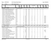
Center Stack Analysis Summary - PPPL EVMS Page
Center Stack Analysis Summary - PPPL EVMS Page
Center Stack Analysis Summary - PPPL EVMS Page

Create successful ePaper yourself
Turn your PDF publications into a flip-book with our unique Google optimized e-Paper software.
NSTX<br />
Supported by<br />
<strong>Analysis</strong> and Qualification Documentation<br />
Columbia U<br />
CompX<br />
General Atomics<br />
FIU<br />
INL<br />
Johns Hopkins U<br />
LANL<br />
LLNL<br />
Lodestar<br />
MIT<br />
Nova Photonics<br />
New York U<br />
ORNL<br />
<strong>PPPL</strong><br />
Princeton U<br />
Purdue U<br />
SNL<br />
Think Tank, Inc.<br />
UC Davis<br />
UC Irvine<br />
UCLA<br />
UCSD<br />
U Colorado<br />
U Illinois<br />
U Maryland<br />
U Rochester<br />
U Washington<br />
U Wisconsin<br />
The NSTX Upgrade Team<br />
Presented By Peter H. Titus<br />
NSTX <strong>Center</strong> <strong>Stack</strong> Upgrade<br />
Peer Review<br />
LSB B318<br />
May 18, 2011<br />
Culham Sci Ctr<br />
U St. Andrews<br />
York U<br />
Chubu U<br />
Fukui U<br />
Hiroshima U<br />
Hyogo U<br />
Kyoto U<br />
Kyushu U<br />
Kyushu Tokai U<br />
NIFS<br />
Niigata U<br />
U Tokyo<br />
JAEA<br />
Hebrew U<br />
Ioffe Inst<br />
RRC Kurchatov Inst<br />
TRINITI<br />
NFRI<br />
KAIST<br />
POSTECH<br />
ASIPP<br />
ENEA, Frascati<br />
CEA, Cadarache<br />
IPP, Jülich<br />
IPP, Garching<br />
ASCR, Czech Rep
Overview<br />
• This presentation is an overview of the analyses and documentation that<br />
provides the basis of the final design for the NSTX Upgrade:<br />
– Since the PDR, over 10,000 person-hours of analyses were performed.<br />
– A total of 47 state-of-the art analyses (electromagnetic, thermal, and stress) have been<br />
documented -most have been checked. (Available at:<br />
http:/nstxupgrade.pppl.gov/Engineering/Calculations/index_Calcs.htm)<br />
– The <strong>Center</strong>stack is the heart of the upgrade.<br />
• This has been carefully analyzed and redundant calculations were made for key<br />
components.<br />
• In addition to component analyses, systems analyses were performed on center<br />
stack, upgraded VV design, upgraded PF support design, and upgraded TF<br />
support design.<br />
– A Digital Coil Protection System, similar to the one used on TFTR, is also planned to<br />
assure that programmed conditions do not exceed operational limits.<br />
– Algorithm development is an integral part of the analysis effort.<br />
– The analyses show that the NSTX-U design can handle all 96<br />
planned operational scenarios.<br />
• A sound design, supported by this robust analysis effort and R&D, has<br />
been developed and we are ready to proceed with construction.<br />
NSTX NSTX <strong>Center</strong> <strong>Stack</strong> Upgrade Final Design Review (6/22/2011)
Our work is governed by:<br />
• The GRD<br />
• NSTX Criteria Document<br />
• ENG33<br />
• http://www.pppl.gov/~neumeyer/NSTX_CSU/Design_Point.html<br />
When a Document is Reviewed and Signed in Accordance with<br />
ENG 33 it:<br />
Satisfies the GRD<br />
Satisfies the NSTX Criteria Document<br />
Has Used or Considered the Latest Design Point Data<br />
Provides Design, Fabrication, Assembly Guidance, Material<br />
Selection in Accordance with Good Engineering Practice<br />
NSTX NSTX <strong>Center</strong> <strong>Stack</strong> Upgrade Final Design Review (6/22/2011) 3
Historically What is Available – Aside from a Wealth of Operating Experience<br />
NSTX CSU Calculation Index<br />
<br />
<br />
<br />
<br />
<br />
Based on Soft Truss<br />
Springs – Loads go<br />
Down<br />
NSTX NSTX <strong>Center</strong> <strong>Stack</strong> Upgrade Final Design Review (6/22/2011) 4
NSTX NSTX <strong>Center</strong> <strong>Stack</strong> Upgrade Final Design Review (6/22/2011) 5
M.Kalish<br />
<br />
<br />
<br />
M.Kalish<br />
<br />
<br />
NSTX NSTX <strong>Center</strong> <strong>Stack</strong> Upgrade Final Design Review (6/22/2011) 6
NSTX NSTX <strong>Center</strong> <strong>Stack</strong> Upgrade Final Design Review (6/22/2011) 7
http://nstx-upgrade.pppl.gov/Engineering/Calculations/index_Calcs.htm >)<br />
Available Documentation:<br />
47 Calculations Total<br />
NSTXU Calculation Web page<br />
http:/nstxupgrade.pppl.gov/Engineering/Calcul<br />
ations/index_Calcs.htm<br />
NSTX NSTX <strong>Center</strong> <strong>Stack</strong> Upgrade Final Design Review (6/22/2011) 8
NSTXU CALC 10-01-02<br />
Global Model (Titus)<br />
NSTXU CALC 12-07-00<br />
Umbrella (Titus/Zhang)<br />
NSTXU CALC 13-03-01<br />
DCPS Influence<br />
Coef(Hatcher/Titus)<br />
NSTXU CALC 13-03-01<br />
DCPS Moment<br />
Coef(Titus/Woolley)<br />
NSTXU CALC 131-01-01<br />
PF Coils (Woolley)<br />
NSTXU CALC 131-01-01<br />
PF Coils (Woolley)<br />
OH/PF Calculations<br />
NSTXU CALC 12-02-00<br />
Dome Rib (Titus)<br />
NSTXU CALC 133-01-<br />
01<br />
PF 1 abc(Myatt)<br />
NSTXU CALC 12-05-00<br />
PF2 and 3 Coil<br />
&Sup(Titus/Zatz)<br />
NSTXU CALC 133-04-00<br />
OH Preload<br />
Bellevilles(Rogoff/Zatz)<br />
NSTXU CALC 12-05-00<br />
PF4and 5 Coil<br />
&Sup(Titus/Zatz)<br />
STXU CALC 133-05-00<br />
S Casing Halo(Brooks/Titus)<br />
NSTXU CALC 132-04-00<br />
TF Outer Leg Support(Zhang)<br />
NSTXU CALC 133-06-00<br />
OH<br />
Cooling(Zolfaghari/Mardenfeld)<br />
NSTXU CALC 133-06-00<br />
OH Stress(Zolfaghari/HM Fan<br />
Dahlgren)<br />
NSTXU CALC 132-11-00<br />
CS Casing<br />
Stresses(Titus/Unassigned)<br />
NSTXU CALC 12-06-00<br />
Alum Block(Titus/Smith)<br />
NSTXU CALC 133-07-<br />
00<br />
OH Coax (Mardenfeld)<br />
NSTXU CALC 55-01-<br />
00<br />
BusBar Khodak<br />
NSTX NSTX <strong>Center</strong> <strong>Stack</strong> Upgrade Final Design Review (6/22/2011)
Machine Protection System Algorithms<br />
Every Calculation Must<br />
Address the DCPS<br />
PF1,2,3 supports, welds bolts – At this<br />
stage, These are just calculated from<br />
influence coefficient matrix loads divided<br />
by weld or bolt area. Proposing to add<br />
Moment Influence Coefficients<br />
PF 4/5 support weldment (see example)<br />
PF4/5 Conductor (Titus)<br />
OH Preload-Launch-TF temperature<br />
dependence<br />
PF1a-OH interaction Stress<br />
Vertical Loads on pedestal load path (TF<br />
Flag Bolts, Pedestal Hilti’s), (Ali)<br />
TF Strap (T. Willard)<br />
– Mostly designed to TF max Current.<br />
DCPS should trip if vertical field exceeds<br />
limit (.24T)<br />
-More – As a Guide on Scope: Use the<br />
number of calculations each with a few<br />
sensitive areas<br />
Hoop Stress in PF1b<br />
Bolt Loads are calculated from the<br />
vertical force and the moment divided<br />
by the width of the bolt pattern<br />
WBS 1.5.2 Upgrade Moment Influence Coefficients<br />
NSTXU-CALC-13-05-00 January 18 2011<br />
Prepared By: Peter Titus,<br />
Reviewed By: R. Woolley, Ron Hatcher, NSTX Cognizant<br />
Engineer<br />
NSTX NSTX <strong>Center</strong> <strong>Stack</strong> Upgrade Final Design Review (6/22/2011) 10
Longer Pulse, More Neutral Beam Power, More Plasma<br />
Current, Increases Heat Load on Vessel Components<br />
WBS 1.1.1 Plasma Facing Components,<br />
Global Thermal <strong>Analysis</strong> of <strong>Center</strong> <strong>Stack</strong> –<br />
Heat Balance NSTX-CALC-11-01-00<br />
Prepared By: Art Brooks, Reviewed by:<br />
Han Zhang, Cognizant Engineer: Jim<br />
Chrzanowski<br />
Active Cooling and Thermal Protection is<br />
Provided for<br />
The 8 Viton O-Rings (2 at each Ceramic<br />
Break, U&L)<br />
PF1b <strong>Center</strong>stack Casing Flange<br />
NSTX NSTX <strong>Center</strong> <strong>Stack</strong> Upgrade Final Design Review (6/22/2011) 11
Longer Pulse, More Neutral Beam Power, More Plasma<br />
Current, Increases Heat Loads on Tiles, Increased Disruption<br />
and Halo Specs Increase Mechanical Loads on Tiles<br />
WBS 1.1.1 Plasma Facing<br />
Components, Stress <strong>Analysis</strong> of Tiles<br />
NSTXU-CALC-11-03-00<br />
Prepared By: Art Brooks,<br />
Reviewed by: TBD, Cognizant<br />
Engineer: Kelsey Tresemer<br />
WBS 1.1.1 Basic Tile<br />
<strong>Analysis</strong> Qualification<br />
December 2010 NSTX-CALC-<br />
11-02-00 Prepared By: Joe<br />
Boales, Reviewed By: Art<br />
Brooks<br />
Cognizant Engineer: Kelsey<br />
Tresemer<br />
NSTX NSTX <strong>Center</strong> <strong>Stack</strong> Upgrade Final Design Review (6/22/2011) 12
Confirmation of ATJ Tensile Stress Allowable<br />
NSTX NSTX <strong>Center</strong> <strong>Stack</strong> Upgrade Final Design Review (6/22/2011)
Sources of Lorentz Loading – The Design Point Spreadsheet<br />
Qualification is based on Max and Min<br />
loads and load combinations for the 96<br />
Equilibria from the Design Point :<br />
With and Without Plasma<br />
Circular or Shaped Plasma<br />
With Inductively Driven Currents<br />
from the Disruption<br />
Max and Min Loads for the Scenarios are<br />
Tabulated<br />
Worst Case Power Supply Loads are<br />
Tabulated<br />
Very few areas are being qualified using<br />
maximum power supply loads from the<br />
design point. They were “Onerous”<br />
• Loads<br />
– Equilibria –Jon<br />
Mennard<br />
– 10% “Headroom” –<br />
Charlie Neumeyer<br />
– Power Supply<br />
Maxima and<br />
Minima – Charlie<br />
Neumeyer<br />
WBS 1.5.2 Force Influence Matrix<br />
Coefficients NSTXU-CALC-13-03-01<br />
Prepared by Ron Hatcher, Review by: Peter<br />
Titus, Cognizant Engineer: Ron Hatcher<br />
NSTX NSTX <strong>Center</strong> <strong>Stack</strong> Upgrade Final Design Review (6/22/2011)<br />
1<br />
4
What do We Do If We Compute the Loads In the <strong>Analysis</strong><br />
Models<br />
One Way is to Compute the Influence Coefficients as you Would For the DCPS and Calculate the<br />
Stress in a Spreadsheet. The Plasma can be Turned On and Off in the Spreadsheet – Remember to add<br />
10% Headroom<br />
WBS 1.1.3 TF Inner Leg Torsional<br />
Shear, Including Input to the DCPS<br />
NSTXU-CALC-132-07-00,<br />
Prepared By: Peter Titus, Reviewed by<br />
Bob Woolley<br />
Cognizant Engineer: Jim Chrzanowski<br />
NSTX NSTX <strong>Center</strong> <strong>Stack</strong> Upgrade Final Design Review (6/22/2011) 15
Screening Results for All 96 Scenaios, With 10% Headroom,<br />
Shaped and Circular Plasmas<br />
EQ1 (&16) produces the highest stress in the <strong>Center</strong><br />
Casing<br />
(Particularly from a Post Circular plasma disruption)<br />
WBS 1.1.3 Structural <strong>Analysis</strong><br />
of the PF1 Coils Leads and<br />
Supports, Rev1<br />
NSTX-CALC-133-01-01<br />
Prepared By: Leonard Myatt,<br />
Reviewed by: TBD, Cognizant<br />
Engineer: Jim Chrzanowski<br />
NSTX NSTX <strong>Center</strong> <strong>Stack</strong> Upgrade Final Design Review (6/22/2011)<br />
16
All New <strong>Center</strong> <strong>Stack</strong> Requires New <strong>Analysis</strong> and Qualification<br />
Cooling and Stress are Critical Sizing Issues<br />
OH Stress Calculation NSTXU-<br />
CALC-133-08-00, OH Stress<br />
Analyses<br />
Prepared by: Ali Zolfaghari,<br />
Reviewed by: H.M. Fan<br />
Cognizant Engineering: Jim<br />
Chrzanowski<br />
Stress Intensity in the OH Coil Due to Self<br />
Currents and Interaction with Current in<br />
Adjacent PF1A Poloidal Field Coil<br />
This Stress is not Accessible by Influence Calcs<br />
NSTX NSTX <strong>Center</strong> <strong>Stack</strong> Upgrade Final Design Review (6/22/2011) 17
OH Cooling Requires Metered Flow to Avoid Excessive<br />
Cooldown Stress<br />
OH Stress Calculation NSTXU-CALC-133-08-00, OH<br />
Stress Analyses<br />
Prepared by: Ali Zolfaghari, Reviewed by: H.M. Fan<br />
Cognizant Engineering: Jim Chrzanowski<br />
Coolant “Wave” Arrives at the<br />
End of the Coil in Different Times<br />
Depending on Path Length in the<br />
Layer<br />
OH Coolant Hole Optimization, NSTXU-CALC-133-06-00<br />
Prepared by: Ali Zolfaghari, Cognizant Engineering: Jim<br />
Chrzanowski<br />
NSTX NSTX <strong>Center</strong> <strong>Stack</strong> Upgrade Final Design Review (6/22/2011) 18
Sizing of the Machine is Driven by the OH Cyclic Stress Limit<br />
The OH Conductor Must have Manufacturing In-Process NDE to Meet Allowables<br />
Gary Voss has Provided Luvata Eddy Current Information – We are Evaluating<br />
whether Volumetric Inspection is Needed.<br />
(No Braze Joint has been Qualified)<br />
<br />
WBS 1.1.3 OH Conductor Fatigue <strong>Analysis</strong> Calculation<br />
Number NSTXU-CALC-133-09, Prepared By: Peter Titus,<br />
Reviewed by Irv Zatz Cognizant Engineer: Jim Chrzanowski<br />
NSTX NSTX <strong>Center</strong> <strong>Stack</strong> Upgrade Final Design Review (6/22/2011) 19
The OH Coax is at Bottom of the OH Coil. It is not Effected by the Vertical Expansion of<br />
the OH , But it is Effected by the Radial Expansion of the OH<br />
WBS 1.1.3 OH Coax and Lead Conductor <strong>Analysis</strong><br />
Calculation Number NSTXU-CALC-133-07<br />
Prepared By: Michael Mardenfeld , Reviewed By:<br />
Unassigned, Cognizant Engineer: Jim Chrzanowski<br />
Support/Flexibility is being Optimized<br />
CTD 425 – Possibly with Primer Can Take Shear<br />
Effect of Kapton is being assessed<br />
This needs to be Strengthened<br />
NSTX NSTX <strong>Center</strong> <strong>Stack</strong> Upgrade Final Design Review (6/22/2011) 20
The OH Must be Held in Contact with the Lower G-10 Support Skirt<br />
to Disallow the Possibility of separation and loading the<br />
terminations and Coolant Connections. This must be done for all<br />
Launching Loads, and Thermal Conditions<br />
OH Coil Pre Load System<br />
CS Structural/Emag<br />
Modeling<br />
A. Zolfaghari<br />
TF Flag<br />
SS Spacer<br />
BV Washer<br />
G-10<br />
OH Coil<br />
G10<br />
No<br />
currents,<br />
Cold TF,<br />
Cold OH<br />
Bellville<br />
stack, 18<br />
mm<br />
preload<br />
and 2.5e7<br />
N/m<br />
spring<br />
constant<br />
TF OH<br />
Launch<br />
Peak<br />
Temp. Temp. TF Current OH Current Force Peak OH Stress Peak TF Stress Displacement<br />
Hot OH, Cold<br />
TF, OH Self EM<br />
Load<br />
OH<br />
Lifted<br />
Case # Notes<br />
COLD COLD OFF OFF OFF 7-14 MPA 7-14 MPA 0.6 mm TF NO 00000 Bellville staff force only<br />
HOT COLD ON OFF OFF 102-115 MPA 38-51 MPA 8.8 mm TF NO 10100 TF grows pushing OH laterally<br />
COLD HOT OFF OFF OFF 10-19 MPA 19-29 MPA 4.6 mm OH NO 01000<br />
COLD HOT OFF ON OFF 125-140 MPA 16-31 MPA 1.6 mm OH NO 01010<br />
TF was off and OH current<br />
was turned on with hoop stress<br />
only<br />
COLD HOT OFF ON ON 123-138 MPA 16-31 MPA 1.9 mm OH NO 01011<br />
TF was off and OH current<br />
was turned on with hoop stress<br />
and launch force.<br />
HOT COLD ON ON ON 117-132 MPA 15-29 MPA 8.2 mm TF NO 10111<br />
Just in case, OH getting<br />
current before heating up<br />
HOT HOT ON ON ON 110-134 MPA 15-19 MPA 8.3 mm NO 11111<br />
Spring dimensions:<br />
26 disk springs/stack<br />
Di = 30.5 mm<br />
De =60.0 mm<br />
t = 3.5 mm<br />
Lo =5.0 mm<br />
E = 206,000. Mpa<br />
mu = 0.3<br />
Required 14 stack to maintain<br />
a minimum of 20,000. lbs.<br />
total load on the OH coil<br />
Required gap = 23.87 mm<br />
(maximum permitted compression<br />
on the stack. Protects overloading<br />
of permitted spring stresses. )<br />
Supporting calculations:<br />
“TFhot OHcold26_14.ppt”<br />
“TFcoldOHhot26_14.ppt”<br />
“TFhotOHhot26_14.ppt”<br />
“Spring Calculations in mm.x<br />
WBS 1.1.3 OH Preload System<br />
& Belleville Spring Design<br />
NSTXU-CALC-133-04-00,<br />
Prepared By: Peter Rogoff,<br />
Tested by T. Kozub, Cognizant<br />
Engineer: Jim Chrzanowski<br />
Note: Spring should be made from SS 301 mate<br />
Depending on Stainless Steel conditions<br />
modulus of elasticity may be slightly diffe<br />
In this case, minimum load on the OH coi<br />
decrease by a small percentage ( say 3 to<br />
while everything else will stay the same.<br />
NSTX NSTX <strong>Center</strong> <strong>Stack</strong> Upgrade Final Design Review (6/22/2011) 21
New Inner PF’s Require Qualification<br />
PF1a<br />
PF1b<br />
PF1c<br />
EQ51<br />
EQ18<br />
EQ33<br />
EQ18<br />
EQ54<br />
WBS 1.1.3 Structural <strong>Analysis</strong> of the PF1<br />
Coils Leads and Supports, Rev1<br />
NSTX-CALC-133-01-01<br />
Prepared By: Leonard Myatt, Reviewed by:<br />
TBD, Cognizant Engineer: Jim Chrzanowski<br />
NSTX NSTX <strong>Center</strong> <strong>Stack</strong> Upgrade Final Design Review (6/22/2011) 22
The 3D PF1a/b model reproduces the max<br />
axisymmetric mandrel stress of away 140<br />
MPa from the most significant 3D<br />
structural features<br />
The winding shell flexure at the lead<br />
opening produces some significant<br />
local stresses:<br />
Mem: 156 MPa (
Shear Stresses are < 7 Mpa – Only CTD 101 K without Primer is Required – But to Have<br />
Fatigue Documentation, We are testing CTD 425 Without Primer .<br />
PF1a<br />
PF1b<br />
PF1c<br />
NSTX NSTX <strong>Center</strong> <strong>Stack</strong> Upgrade Final Design Review (6/22/2011) 24
Past Difficulties with the TF Joint Demand a New Robust Joint<br />
Design<br />
TF Flex Joint and TF Bundle Stub NSTXU-CALC-132-06-00<br />
Prepared By: Tom Willard, Reviewed by: Ali Zolfaghari<br />
Cognizant Engineer: Jim Chrzanowski<br />
NSTX NSTX <strong>Center</strong> <strong>Stack</strong> Upgrade Final Design Review (6/22/2011) 25
Contact Pressures are Maintained with a Large Margin - Based on Lessons Learned form Original NSTX Flag<br />
Contact Pressure<br />
TF Flex Joint and TF Bundle Stub NSTXU-CALC-<br />
132-06-00<br />
Prepared By: Tom Willard, Reviewed by: Ali<br />
Zolfaghari<br />
Cognizant Engineer: Jim Chrzanowski<br />
Current Density<br />
Distribution –<br />
Temperature Agrees<br />
with Han’s Coupled<br />
EM-Thermal <strong>Analysis</strong><br />
TF Coupled Thermal Electromagnetic<br />
Diffusion <strong>Analysis</strong>,<br />
NSTXU-CALC-132-05-01,<br />
Prepared By: Han Zhang, Reviewed by Yuhu<br />
Zhai,<br />
Cognizant Engineer: Jim Chrzanowski<br />
Temperature<br />
Distribution at EOP<br />
NSTX NSTX <strong>Center</strong> <strong>Stack</strong> Upgrade Final Design Review (6/22/2011) 26
Up to 40% of the Plasma Current is Inductively Driven in The <strong>Center</strong>stack During a Disruption<br />
WBS 1.1.1 Disruption <strong>Analysis</strong> of Passive Plates, Vacuum Vessel & Components<br />
NSTXU-CALC-12-01-01 Rev 1 April, 2011<br />
Prepared By: Peter Titus, Contributing Authors: A. Brooks, Srinivas Avasarala,<br />
J. Boales Reviewed By: Yu Hu Zhai, Cognizant Engineer: Peter Titus<br />
Dynamic Results ~ 1 MPa<br />
NSTX NSTX <strong>Center</strong> <strong>Stack</strong> Upgrade Final Design Review (6/22/2011) 27
The Tall Narrow <strong>Center</strong>stack Could Experience Excessive Lateral Loads If Peaking Factors are Sustained.<br />
WBS 1.1.3 Magnet Systems, Halo Current<br />
<strong>Analysis</strong> of <strong>Center</strong> <strong>Stack</strong><br />
NSTXU-CALC-133-05-00<br />
Prepared By: Art Brooks, Reviewed by:<br />
Peter Titus,<br />
Cognizant Engineer: Jim Chrzanowski<br />
Stress Due<br />
Halo Current<br />
Strike<br />
NSTX NSTX <strong>Center</strong> <strong>Stack</strong> Upgrade Final Design Review (6/22/2011) 28
Stress Due Thermal Distribution<br />
Stress Due to PF Loads<br />
WBS 1.1.1 Plasma Facing Components,<br />
Global Thermal <strong>Analysis</strong> of <strong>Center</strong> <strong>Stack</strong> –<br />
Heat Balance NSTX-CALC-11-01-00<br />
Prepared By: Art Brooks, Reviewed by:<br />
Han Zhang, Cognizant Engineer: Jim<br />
Chrzanowski<br />
WBS 1.1.3 Structural <strong>Analysis</strong> of the PF1<br />
Coils Leads and Supports, Rev1<br />
NSTX-CALC-133-01-01<br />
Prepared By: Leonard Myatt, Reviewed by:<br />
TBD, Cognizant Engineer: Jim Chrzanowski<br />
NSTX Upgrade <strong>Center</strong>stack Casing Stress <strong>Summary</strong> NSTXU-<br />
CALC-133-03-00<br />
Rev 0 May 2011 Prepared By: Peter Titus, <strong>PPPL</strong> Engineering<br />
<strong>Analysis</strong> Branch, Contributing Authors: A. Brooks, L.Myatt<br />
Reviewed By: Unassigned<br />
Jim Chrzanowski, NSTX Cognizant Engineer<br />
Torsions + Thermal +Lorentz +Inductive + Halo<br />
50 + 261 + 42 + 1 + 60 = 414<br />
NSTX NSTX <strong>Center</strong> <strong>Stack</strong> Upgrade Final Design Review (6/22/2011) 29
Bellows Allow Vertical Expansion of the <strong>Center</strong>stack Casing – This is Axial Motion, but Lateral and Torsional Loads Exist<br />
Modulus of Elasticity = 29,000,000.<br />
stainless steel (FEA and EJMA)<br />
t = variable ( .02, .025, .03 ) in.<br />
Node #49436 – central, RBE2 independent<br />
Deformations and loads applied through it.<br />
Di = 38.0 inches<br />
Do =40.25 inches<br />
w = 1.095 in. convolution<br />
height<br />
q = 1.0 in. convolution<br />
pitch<br />
WBS 1.1.3 <strong>Center</strong> <strong>Stack</strong> Casing Bellows,<br />
Calculation Number NSTXU-CALC-133-10-00<br />
Prepared By: Peter Rogoff, Reviewed by Irv Zatz<br />
Cognizant Engineer: Jim Chrzanowski<br />
•Halo Current Loads (upper bellows only). Reference<br />
calculation #NSTX CALC 133-04-00.<br />
Fixed : x, y, z, Rx ,Ry, Rz<br />
•The upper bellows must allow thermal motion due to the<br />
bake-out and the normal operation where heat from the<br />
plasma is transferred to the CS casing through the<br />
insulating tiles. Reference calculation # NSTX CALC 11-01-<br />
00.<br />
Note: All stresses reported are for cquad4 surface “Z2” . This is the bellows inside surface.<br />
•The upper bellows must support the seismic loads,<br />
Reference calculation #NSTX CALC 10-01-02.<br />
•The upper and lower bellows transmit some portion of the<br />
torsional moment from the upper vessel structure to the<br />
center stack casing. This moment comes through the<br />
umbrella structure, Reference calculation # NSTX CALC 10-<br />
01-02.<br />
•Pressure due to vacuum conditions.<br />
These calculations were performed using:<br />
• EJMA (Expansion Joint Manufacturers Association)<br />
Basic equations presented in section 4.13 of the manual.<br />
•NASTRAN Version MSC FEA x64 2010.1.2 finite element<br />
code.<br />
NSTX NSTX <strong>Center</strong> <strong>Stack</strong> Upgrade Final Design Review (6/22/2011) 30
The Upper End of the <strong>Center</strong>stack Casing<br />
is Only Coupled to the Rest of the<br />
Machine Through the Bellows<br />
WBS 1.1.3 OH & PF1 & 2 Electromagnetic<br />
Stability Analyses<br />
NSTXU-CALC-133-11-00 Rev 0 March 2<br />
2010<br />
Prepared By: Peter Titus, Ali Zolfaghari,<br />
Reviewed By: H.M.Fan,<br />
Cognizant Engineer: Jim Chrzanowski<br />
NSTX NSTX <strong>Center</strong> <strong>Stack</strong> Upgrade Final Design Review (6/22/2011) 31
Single Width “Blade” Or Bitter Magnet Design<br />
Introduces Possibility of Transient Coupled<br />
Electromagnetic Thermal Diffusion<br />
TF coil<br />
air<br />
Arch: with anisotropic mat prop to<br />
simulate strips<br />
Upper flag: high strength copper:<br />
with 1/0.8 resistivity and 80% thermal<br />
conductivity<br />
TF coil<br />
Electrical insulation<br />
Contact area<br />
This Calculation<br />
Determines Current<br />
Distributions<br />
Lower flag: CuCrZr<br />
B. Toroidal field plot<br />
TF Coupled Thermal Electromagnetic Diffusion <strong>Analysis</strong>,<br />
NSTXU-CALC-132-05-01,<br />
Prepared By: Han Zhang, Reviewed by Yuhu Zhai,<br />
Cognizant Engineer: Jim Chrzanowski<br />
This Calculation<br />
Determines Temperatures,<br />
and Stresses<br />
NSTX NSTX <strong>Center</strong> <strong>Stack</strong> Upgrade Final Design Review (6/22/2011) 32
Single Width “Blade” Or Bitter Magnet Design Introduces Possibility of<br />
Transient Coupled Electromagnetic Thermal Diffusion<br />
Highly Localized Temperatures in the TF reach 113 degrees<br />
C – Testing is being extended to 115C. If tests are not<br />
favorable, TF Profile adjustment or control of ramp-down<br />
OOP loading will be used.<br />
TF Coupled Thermal Electromagnetic<br />
Diffusion <strong>Analysis</strong>,<br />
NSTXU-CALC-132-05-01,<br />
Prepared By: Han Zhang, Reviewed by Yuhu<br />
Zhai,<br />
Cognizant Engineer: Jim Chrzanowski<br />
NSTX NSTX <strong>Center</strong> <strong>Stack</strong> Upgrade Final Design Review (6/22/2011) 33
TF Flex Must be Conduction Cooled from Its Ends – Higher<br />
Resistivity High Strength Friction Stir Welded Flag Must<br />
Perform Adequately Thermally<br />
TF Coupled Thermal Electromagnetic Diffusion<br />
<strong>Analysis</strong>, (Part 2)<br />
NSTXU-CALC-132-05-01,<br />
Prepared By: Han Zhang, Reviewed by Yuhu Zhai,<br />
Cognizant Engineer: Jim Chrzanowski<br />
TF Cool-down using FCOOL CALC-132-10-00<br />
Prepared by: Ali Zolfaghari, Reviewed by: Mike Kalish<br />
Cognizant Engineer: Jim Chrzanowski<br />
NSTX NSTX <strong>Center</strong> <strong>Stack</strong> Upgrade Final Design Review (6/22/2011) 34
Higher Resistivity High Strength Friction Stir Welded Flag Must<br />
Perform Adequately<br />
TF Coupled Thermal Electromagnetic Diffusion<br />
<strong>Analysis</strong>, (Part 2)<br />
NSTXU-CALC-132-05-01,<br />
Prepared By: Han Zhang, Reviewed by Yuhu Zhai,<br />
Cognizant Engineer: Jim Chrzanowski<br />
NSTX NSTX <strong>Center</strong> <strong>Stack</strong> Upgrade Final Design Review (6/22/2011) 35
The Tokamak is Multiply Redundant, Global Model Model Simulations are Required<br />
Global Model Is Used For:<br />
Addressing Statically Indeterminate Structures<br />
Selecting Worst Cases<br />
Scoping Studies<br />
Providing Boundary Conditions for Other Models<br />
Cross-Checking other Models<br />
Seismic <strong>Analysis</strong><br />
<strong>Analysis</strong> of TF Outer<br />
Leg, NSTXU-CALC-<br />
132-04-00,<br />
Prepared By: Han<br />
Zhang, Reviewed by<br />
Peter Titus<br />
Cognizant Engineer:<br />
Mark Smith<br />
WP 1.1.1 Seismic<br />
<strong>Analysis</strong> NSTXU-<br />
CALC-10-02-00,<br />
Prepared by Peter<br />
Titus, Reviewed by F.<br />
Dahlgren, Cognizant<br />
Engineer: Peter Titus<br />
WP 1.1.0 NSTX<br />
Upgrade Global<br />
Model – Model<br />
Description, Mesh<br />
Generation, and<br />
Results NSTXU-<br />
CALC-10-01-02<br />
Prepared by Peter<br />
Titus, Reviewed by<br />
Han Zhang,<br />
Cognizant<br />
Engineer: Peter<br />
Titus<br />
NSTX NSTX <strong>Center</strong> <strong>Stack</strong> Upgrade Final Design Review (6/22/2011) 36
Spectral Acceleration, g<br />
Global Model Model is Used for the Seismic <strong>Analysis</strong><br />
MCE and 5% Damped MCE Ground Motion<br />
0.400<br />
0.350<br />
0.300<br />
0.250<br />
0.200<br />
MCE<br />
5% Damped MCE<br />
0.150<br />
0.100<br />
WP 1.1.1 Seismic <strong>Analysis</strong> NSTXU-CALC-10-02-00,<br />
Prepared by Peter Titus, Reviewed by F. Dahlgren,<br />
Cognizant Engineer: Peter Titus<br />
0.050<br />
0.000<br />
0.00 0.20 0.40 0.60 0.80 1.00 1.20 1.40 1.60 1.80 2.00<br />
Period, Sec<br />
NSTX NSTX <strong>Center</strong> <strong>Stack</strong> Upgrade Final Design Review (6/22/2011) 37
TF In-Plane Load is Four Times Larger<br />
Aluminum<br />
Blocks are<br />
Cast, Not<br />
Forged<br />
WBS 1.1.2 Upgrade TF to<br />
Umbrella Structure Aluminum<br />
Block Connection<br />
NSTXU-CALC-12-06-00,<br />
Prepared By: Peter Titus,<br />
Reviewed By: Mark Smith,<br />
NSTX Cognizant Engineer<br />
Mark Smith<br />
<strong>Analysis</strong> of TF Outer Leg,<br />
NSTXU-CALC-132-04-00,<br />
Prepared By: Han Zhang,<br />
Reviewed by Peter Titus<br />
Cognizant Engineer: Mark<br />
Smith<br />
WBS 1.1.2 Ring Bolted Joint,<br />
NSTXU-CALC-132-11-00<br />
Prepared By: Peter Rogoff,<br />
Reviewed By Irv Zatz,<br />
Cognizant Engineer: Mark Smith<br />
NSTX NSTX <strong>Center</strong> <strong>Stack</strong> Upgrade Final Design Review (6/22/2011) 38
Out-of-Plane Torque is Much Larger Inner Leg Torsional Shear is Limiting<br />
TF Inner Leg Torsional Shear<br />
Bob Woolley’s<br />
Moment Sum<br />
WBS 1.1.3 TF Inner Leg Torsional Shear,<br />
Including Input to the DCPS<br />
NSTXU-CALC-132-07-00,<br />
Prepared By: Peter Titus, Reviewed by Bob<br />
Woolley<br />
The Max torsional shear is 24<br />
Cognizant Engineer: Jim Chrzanowski<br />
MPa with an allowable of 21.7<br />
MPa<br />
NSTX NSTX <strong>Center</strong> <strong>Stack</strong> Upgrade Final Design Review (6/22/2011) 39
NSTX NSTX <strong>Center</strong> <strong>Stack</strong> Upgrade Final Design Review (6/22/2011)
Calculation of Inner Leg Torsional Shear Using the Global Model<br />
Derived Influence Coefficients<br />
WBS 1.1.3 TF Inner Leg<br />
Torsional Shear,<br />
Including Input to the<br />
DCPS<br />
NSTXU-CALC-132-07-00,<br />
Prepared By: Peter<br />
Titus, Reviewed by Bob<br />
Woolley<br />
Cognizant Engineer: Jim<br />
Chrzanowski<br />
NSTX NSTX <strong>Center</strong> <strong>Stack</strong> Upgrade Final Design Review (6/22/2011) 41
Calculation of Inner Leg Torsional Shear Using the Global Model<br />
Derived Influence Coefficients<br />
WBS 1.1.3 TF Inner Leg<br />
Torsional Shear,<br />
Including Input to the<br />
DCPS<br />
NSTXU-CALC-132-07-00,<br />
Prepared By: Peter<br />
Titus, Reviewed by Bob<br />
Woolley<br />
Cognizant Engineer: Jim<br />
Chrzanowski<br />
NSTX NSTX <strong>Center</strong> <strong>Stack</strong> Upgrade Final Design Review (6/22/2011) 42
Vertical Position (m)<br />
Bob Wooley’s Calculation of Inner<br />
Leg Torsional Shear Using Mark<br />
Smith’s Global Model Stiffnesses<br />
Important Node Numbers In Torsion Membrane Model<br />
3<br />
2<br />
1 1638<br />
1488<br />
1435<br />
1618<br />
1630<br />
1163<br />
1618<br />
1638<br />
1163<br />
1435<br />
0<br />
1; 2000<br />
-1<br />
-2<br />
363 371<br />
383 513566<br />
838<br />
1;2000<br />
838<br />
-3<br />
0 1 2 3<br />
Radial Position (m)<br />
Peak torsional shear stress in<br />
383<br />
the TF centerstack calculated<br />
by these methods is 25.18<br />
MPa. Bob’s Shears are Up-<br />
Down Symmetric<br />
363<br />
566<br />
NSTX NSTX <strong>Center</strong> <strong>Stack</strong> Upgrade Final Design Review (6/22/2011) 43
With Similar Stiffnesses to Bob Woolley/Mark Smith, Titus’s <strong>Analysis</strong> Produces Up-Down Symmetry<br />
WP 1.1.0 NSTX<br />
Upgrade Global<br />
Model – Model<br />
Description, Mesh<br />
Generation, and<br />
Results NSTXU-<br />
CALC-10-01-02<br />
Prepared by Peter<br />
Titus, Reviewed<br />
by Unassigned,<br />
Cognizant<br />
Engineer: Peter<br />
Titus<br />
WBS 1.1.2<br />
Lid/Spoke<br />
Assembly, Upper<br />
& Lower<br />
NSTX-CALC-12-<br />
08-00 Rev 0 May<br />
2011<br />
Prepared by:<br />
Peter Titus,<br />
Reviewed By:<br />
Unassigned,<br />
Cognizant<br />
Engineer: Mark<br />
Smith<br />
NSTX NSTX <strong>Center</strong> <strong>Stack</strong> Upgrade Final Design Review (6/22/2011) 44
NSTX NSTX <strong>Center</strong> <strong>Stack</strong> Upgrade Final Design Review (6/22/2011) 45
CTD Fatigue Tests<br />
100°C test cycle with 16 samples<br />
2 samples tested > 60.000 load cycles<br />
80°C test cycle with 10 samples<br />
no sample tested up to 60.000 load<br />
cycles<br />
Peak to Average at<br />
the Mid Plane of the<br />
SBS Sample is an<br />
additional Factor of<br />
1.30<br />
46<br />
46<br />
NSTX NSTX <strong>Center</strong> <strong>Stack</strong> Upgrade Final Design Review (6/22/2011)
Peak to Average at<br />
the Mid Plane of the<br />
SBS Sample is an<br />
additional Factor of<br />
1.30<br />
NSTX NSTX <strong>Center</strong> <strong>Stack</strong> Upgrade Final Design Review (6/22/2011) 47
Peak to Average at<br />
the Mid Plane of the<br />
SBS Sample is an<br />
additional Factor of<br />
1.30<br />
NSTX NSTX <strong>Center</strong> <strong>Stack</strong> Upgrade Final Design Review (6/22/2011) 48
With Two Independent Methods, Both Results for the Maximum<br />
TF Inner Leg Torsional Shear are Similar<br />
Bob Woolley Gets 25.18 Mpa<br />
P. Titus Gets:<br />
Based on the DCPS influence coefficient TF inner leg upper<br />
corner torsional shear stresses, for all scenarios, are all below<br />
20 MPa with and without plasma. Rigorously these should have<br />
the 10% headroom applied (the coefficients do not include this)<br />
- So the torsional shear stress to compare with the allowable is<br />
22 MPa.<br />
We have CTD -425 Qualification for 20 Mpa at 100C for ~<br />
300,000 cycles<br />
-And We Have DCPS Input Algorithm for TF Torsional Shear<br />
NSTX NSTX <strong>Center</strong> <strong>Stack</strong> Upgrade Final Design Review (6/22/2011) 49
Out-of-Plane Torque Equations in the Design Point Spreadsheet<br />
WBS 1.1.0 NSTXU 132-03-00, Torques On TF<br />
Conductors & Resulting Torsion & Shear Stress in<br />
NSTX CSU, 04 May2010 Design Point,<br />
Prepared by R. Woolley Reviewed by Peter Titus,<br />
Cognizant Engineer: Peter Titus<br />
Global Torque Sums Agree with FEA<br />
Calculations by Willard and Titus<br />
Net TF SystemOuterLeg Torque<br />
3519.9<br />
1 N - m<br />
3692.0<br />
13191<br />
I<br />
I<br />
PF1BU<br />
PF2U<br />
I<br />
1kA<br />
I<br />
1kA<br />
PF2L<br />
PF1BL<br />
16497<br />
4293.8<br />
I<br />
I<br />
PF3U<br />
I<br />
I<br />
1kA<br />
PF1AU<br />
PF1CU<br />
I<br />
1kA<br />
PF3L<br />
I<br />
1kA<br />
PF1CL<br />
PF1AL<br />
Net Upper Half TF SystemTorque<br />
1 N - m<br />
1580.6<br />
5197.5<br />
I<br />
PF1BU<br />
I<br />
PF2U<br />
I<br />
1kA<br />
I<br />
1kA<br />
I<br />
PF4<br />
56813.9<br />
1kA<br />
IOH<br />
13563.1<br />
1kA<br />
PF1BL<br />
PF2L<br />
1851.5<br />
21915.7<br />
I<br />
PF5U<br />
118636.5<br />
1kA<br />
I<br />
I<br />
2260.9<br />
PF1CU<br />
PF3U<br />
I<br />
1kA<br />
I<br />
1kA<br />
I<br />
PF1CL<br />
PF3L<br />
713308.9<br />
PF1AU<br />
I<br />
1kA<br />
I<br />
plasma<br />
1 MA<br />
PF1AL<br />
NSTX NSTX <strong>Center</strong> <strong>Stack</strong> Upgrade Final Design Review (6/22/2011) 50
Hoop Tension Develops from Thermal Distribution<br />
TF Coupled Thermal Electromagnetic Diffusion <strong>Analysis</strong>, (Part 2)<br />
NSTXU-CALC-132-05-01,<br />
Prepared By: Han Zhang, Reviewed by Yuhu Zhai,<br />
Cognizant Engineer: Jim Chrzanowski<br />
NSTX NSTX <strong>Center</strong> <strong>Stack</strong> Upgrade Final Design Review (6/22/2011) 51
Hoop Tension Develops from Thermal Distribution. But Not Where<br />
Torsional Shear is Greatest.<br />
TF Coupled Thermal<br />
Electromagnetic<br />
Diffusion <strong>Analysis</strong>,<br />
(Part 2)<br />
NSTXU-CALC-132-<br />
05-01,<br />
Prepared By: Han<br />
Zhang, Reviewed by<br />
Yuhu Zhai,<br />
Cognizant Engineer:<br />
Jim Chrzanowski<br />
WBS 1.1.3 TF Inner Leg Torsional Shear,<br />
Including Input to the DCPS<br />
NSTXU-CALC-132-07-00,<br />
Prepared By: Peter Titus, Reviewed by<br />
Bob Woolley<br />
Cognizant Engineer: Jim Chrzanowski<br />
NSTX NSTX <strong>Center</strong> <strong>Stack</strong> Upgrade Final Design Review (6/22/2011) 52
CTD 425 is a Blend which Uses the CTD 450 Cyanate Ester<br />
Primer . Adhesion of the insulation is expected to be<br />
governed by Cyanate Ester Properties. Zero Shear Tension<br />
Capacity at 80C is 60 Mpa.<br />
If there is Tensile or Shear Failure, It is desirable to have<br />
debonding at the Copper /Insulator Interface.<br />
From the CTD 425 Fatigue Qualification:<br />
From Gary Voss Paper on Cyanate Ester<br />
NSTX NSTX <strong>Center</strong> <strong>Stack</strong> Upgrade Final Design Review (6/22/2011)
Inner leg Torques are Partially Reacted by Connections to the Spoked Lids<br />
The Upper and Lower G-10 Crowns<br />
Transmit Torsional Shear from the<br />
Spoked Lids to the TF Flag Extensions<br />
The Final Design uses a Friction<br />
based Preloaded “Clutch Face”<br />
Approach. Figures Below Show<br />
Earlier Designs that Illustrate the<br />
Mechanics of the Interface<br />
Determination of Shear Forces between the TF Conductors<br />
NSTX-CALC-132-08-00<br />
Prepared by: Ali Zolfaghari, Reviewed by: Tom Willard<br />
Cognizant Engineering: Jim Chrzanowski<br />
NSTX NSTX <strong>Center</strong> <strong>Stack</strong> Upgrade Final Design Review (6/22/2011) 54
Moment From Spoked Lid <strong>Analysis</strong><br />
Pinned Connections are Used on Top and Bottom<br />
Determination of Shear Forces<br />
between the TF Conductors<br />
NSTX-CALC-132-08-00<br />
Prepared by: Ali Zolfaghari,<br />
Reviewed by: Tom Willard<br />
Cognizant Engineering: Jim<br />
Chrzanowski<br />
See: NSTXU 132-03-00,<br />
Torques On TF Conductors<br />
& Resulting Torsion &<br />
Shear Stress in NSTX CSU,<br />
by R. Woolley or,<br />
TF Inner Leg Torsional<br />
Shear, Including Input to<br />
the DCPS<br />
NSTXU-CALC-132-07-00,<br />
Prepared By: Peter Titus,<br />
For Inner Leg Shear<br />
NSTX NSTX <strong>Center</strong> <strong>Stack</strong> Upgrade Final Design Review (6/22/2011) 55
Out-of-Plane Torque is Much Larger. Most is taken by the Vessel, Some<br />
by the TF Outboard Legs, A little by the CS Casing and Central Column<br />
OOP Forces for Scenario<br />
#79 Summed from the joint<br />
flags out. From the<br />
aluminum blocks out the<br />
sum is 127000 N for the<br />
upper half.<br />
NSTX NSTX <strong>Center</strong> <strong>Stack</strong> Upgrade Final Design Review (6/22/2011)
Out-of-Plane Torque Must be Taken by Existing<br />
Structural Load Paths – Can the Vessel Take It<br />
Basic Elements of the OOP Load Carrying “Logic” Remain: i.e.<br />
Global Twist is Carried Predominantly by the Vacuum Vessel Equatorial Region With Some Help from TF<br />
TF OOP Loads are Still transferred to Umbrella Structure and Knuckle Clevis<br />
We tried other things – “Diamond Truss” , “Top Hat” and Truss to the Cell Walls<br />
WBS 1.1.2 Vessel Rework for the Neutral<br />
Beam and Thomson Scattering Port<br />
NSTXU-CALC-24-01-00<br />
Prepared By: T. Willard Reviewed by: A.<br />
Zolfaghari<br />
Cognizant Engineers: M. Smith, G. Labik,<br />
C. Priniski<br />
NSTX NSTX <strong>Center</strong> <strong>Stack</strong> Upgrade Final Design Review (6/22/2011) 57
Outer Leg In-Plane and Out-of-Plane Support Many<br />
Concepts Were Tried – Many had Interference<br />
Problems<br />
Diamond Truss Pinned Ring Rigid Truss Rigid Ring to Existing Clevis Soft Springs to Existing Clevis<br />
Outer Leg Support<br />
Must Control:<br />
Copper Stress<br />
Bending Related Bond<br />
Shear<br />
Loads at Attachment<br />
Points<br />
Displacements<br />
<strong>Analysis</strong> of TF Outer Leg,<br />
NSTXU-CALC-132-04-00,<br />
Prepared By: Han Zhang,<br />
Reviewed by Peter Titus<br />
Cognizant Engineer: Mark<br />
Smith<br />
WBS 1.1.2 TF Strut to<br />
Vessel Knuckle Clevis<br />
Connection<br />
NSTXU-CALC-132-09-00<br />
Rev 0 March 2011, Prepared<br />
By: Peter Titus,<br />
Reviewed by Han Zhang,<br />
Mark Smith, NSTX<br />
Cognizant Engineer<br />
NSTX NSTX <strong>Center</strong> <strong>Stack</strong> Upgrade Final Design Review (6/22/2011) 58
Existing Clevis Was Offset From the Surface of the Vessel and Was<br />
Held On by 5/16 Screws – It Had Little Load Capacity<br />
NSTX NSTX <strong>Center</strong> <strong>Stack</strong> Upgrade Final Design Review (6/22/2011) 59
Welded Clevis Replacement<br />
WBS 1.1.2 TF Strut to Vessel Knuckle<br />
Clevis Connection<br />
NSTXU-CALC-132-09-00 Rev 0 March<br />
2011, Prepared By: Peter Titus,<br />
Reviewed by Han Zhang, Mark Smith,<br />
NSTX Cognizant Engineer<br />
NSTX NSTX <strong>Center</strong> <strong>Stack</strong> Upgrade Final Design Review (6/22/2011) 60
Materials and Allowables<br />
718 Typical Mechanical Properties At Room Temperature:<br />
Ultimate Tensile Yield Strength Elongation in Elastic Modulus<br />
Strength (0.2 % offset) 50 mm (2") (Tension)<br />
MPa ksi MPa ksi % GPa 106 psi<br />
1240 180 1036 150 12 211 30.6<br />
1/3 Ult=60ksi 2/3 yield=100 ksi Sm=60ksi<br />
The allowed shear stress is .6*sm = 36 ksi Ref NSTX Criteria Doc<br />
The pin shear is 22185/(.75^2*pi/4)/2 =<br />
24.1ksi for 3/4 pins in double shear<br />
The pin shear is 22185/(1.0^2*pi/4)/2 =<br />
14.1ksi for 1 inch pins in double shear<br />
Pins are .75 inch in this<br />
model, but they must be tight<br />
fitting or there are bending<br />
Stresses.<br />
Actual Pin shear with 1.5 shear stress peak<br />
for ¾ in pins is 24.1*1.5 =36.75ksi<br />
Tresca is then 73.5 ksi,<br />
for 2 on stress or<br />
147 ksi for r=0 (circles), Life = ~90000 cycles<br />
90000>60000 (NSTX GRD)<br />
For Tresca = 73.6, life>1e7<br />
1e7/60000 = 167 >> 20<br />
Satisfies the GRD Requirement for<br />
60,000 cycles<br />
NSTX NSTX <strong>Center</strong> <strong>Stack</strong> Upgrade Final Design Review (6/22/2011)
Clamps Produce Local Stress Concentrations<br />
– Leg Braces Help – Do we Need Them<br />
This is the result<br />
with/without coil<br />
reinforcement.<br />
Without<br />
reinforcement, max<br />
stress is 90MPa.<br />
With reinforcement,<br />
it reduces to 86MPa.<br />
Comparing with<br />
previous spring<br />
design, 175MPa,<br />
it seems the tie bar<br />
stiffness is the main<br />
factor for coil<br />
stress..<br />
“Leg Brace”<br />
“Clamp”<br />
<strong>Analysis</strong> of TF Outer Leg,<br />
NSTXU-CALC-132-04-00,<br />
Prepared By: Han Zhang,<br />
Reviewed by Peter Titus<br />
Cognizant Engineer: Mark<br />
Smith<br />
NSTX NSTX <strong>Center</strong> <strong>Stack</strong> Upgrade Final Design Review (6/22/2011) 62
“Clamp”<br />
WBS 1.1.2 TF Clamp Assembly<br />
NSTXU-CALC-132-10-00 Rev 0 March<br />
2011, Prepared By: Peter Rogfff<br />
Reviewed by Unassigned, Mark Smith,<br />
NSTX Cognizant Engineer<br />
“Clamp”<br />
“Leg Brace”<br />
NASTRAN MPC<br />
ANSYS CP<br />
NSTX NSTX <strong>Center</strong> <strong>Stack</strong> Upgrade Final Design Review (6/22/2011) 63
K*l/r for<br />
2 inch<br />
PipeStrut<br />
2” Sch<br />
160 Pipe<br />
Strut<br />
Needing<br />
Bending<br />
Stress<br />
Evaluation<br />
Ratio of Euler<br />
Buckling<br />
Stress to the<br />
Yield Stress<br />
AISC Allowable =<br />
.43*Yield =12900psi<br />
=37000/2/cos(33.5)<br />
= 22185 Lb<br />
Applied Stress = 10132<br />
psi<br />
Ratio of AISC<br />
Allowable to the<br />
Yield Stress<br />
NSTX NSTX <strong>Center</strong> <strong>Stack</strong> Upgrade Final Design Review (6/22/2011)
The Ring Supports the Bursting Loads and OOP rotations. The Bolted Joint is Designed for Tension and Moments<br />
Loads with SPCDs and Moments<br />
Total Loads<br />
Bolt Pre Load = 44,000. lbs<br />
Total Distance between nodes #47432 and #47431 = 30.4 inches<br />
Calculations based on standard equations, See above<br />
See next slide<br />
Problem: 1.0 in. dia. Bolt , As= .663 in^2, Yield = 100.ksi, Based on 2/3 yield = 66.7 ksi.<br />
WBS 1.1.2 Ring Bolted Joint,<br />
NSTXU-CALC-132-11-00<br />
Prepared By: Peter Rogoff,<br />
Reviewed By Irv Zatz,<br />
Cognizant Engineer: Mark Smith<br />
Fp = 66.7ksi x .663in^2 = 44.22 Kips per bolt, If mu = .3, Fs = 44.22 Kips X .3 = 13,266 lbs/bolt<br />
Typical “nut factor” see the torque equation<br />
For two bolts Fs= 26532. lbs And required torque = 44,220 lbs. x .2 x 1.0 in.= 8,844 lb-in<br />
NSTX NSTX <strong>Center</strong> <strong>Stack</strong> Upgrade Final Design Review (6/22/2011) 65
Out-of-Plane Loads Are Transferred from the TF to the Vessel Via the<br />
Umbrella Structure as Well. Original Legs Were Too Weak<br />
WBS 1.1.2 NSTX Upgrade Umbrella Arch and<br />
Foot Reinforcements, Local Dome Details,<br />
NSTXU-CALC-12-07-00 May 2011Prepared by:<br />
Peter Titus, Han Zhang, Reviewed By: Irv<br />
Zatz, Cognizant Engineer: Mark Smith<br />
NSTX NSTX <strong>Center</strong> <strong>Stack</strong> Upgrade Final Design Review (6/22/2011) 66
Titus’s Model<br />
Han Zhang’s Model<br />
4.5 in<br />
4.0 in<br />
3 in by<br />
Real<br />
Constant<br />
3.55<br />
in<br />
80*4/3*4^2/3.55^2 = 143 MPa<br />
WBS 1.1.2 NSTX Upgrade Umbrella Arch and Foot Reinforcements,<br />
Local Dome Details, NSTXU-CALC-12-07-00 May 2011Prepared by:<br />
Peter Titus, Han Zhang, Reviewed By: Irv Zatz, Cognizant Engineer:<br />
Mark Smith<br />
NSTX NSTX <strong>Center</strong> <strong>Stack</strong> Upgrade Final Design Review (6/22/2011)
OOP and Vertical Load from Umbrella Legs, PF1c 2,and 3 Loads are<br />
Applied to the Ribs. Solid Models Needed Updating<br />
Bruce Paul Built the Solid Model of<br />
the Dome Rib Based on Non-<br />
Conformance Report<br />
NSTX NSTX <strong>Center</strong> <strong>Stack</strong> Upgrade Final Design Review (6/22/2011)
Dished Head Supports PF1c,2, and 3 Loads<br />
Sliding Block Allows Bake-Out Motion<br />
WBS 1.1.2 NSTX Upgrade Umbrella Arch and<br />
Foot Reinforcements, Local Dome Details,<br />
NSTXU-CALC-12-07-00 May 2011Prepared by:<br />
Peter Titus, Han Zhang, Reviewed By: Irv<br />
Zatz, Cognizant Engineer: Mark Smith<br />
NSTX NSTX <strong>Center</strong> <strong>Stack</strong> Upgrade Final Design Review (6/22/2011) 69
Out-of-Plane Torque Are Taken by Existing Structural Load Paths – Torque<br />
from Umbrella Structure Goes to Umbrella Legs – And to Upper Spoked Lid<br />
WBS 1.1.2 Lid/Spoke Assembly,<br />
Upper & Lower<br />
NSTX-CALC-12-08-00 Rev 0 May<br />
2011<br />
Prepared by: Peter Titus, Reviewed<br />
By: Unassigned,<br />
Cognizant Engineer: Mark Smith<br />
Upper Spoked<br />
Lid Must Flex<br />
Upward to<br />
Allow Thermal<br />
Growth of the<br />
<strong>Center</strong>stack<br />
NSTX NSTX <strong>Center</strong> <strong>Stack</strong> Upgrade Final Design Review (6/22/2011) 70
Lower Out-of-Plane Torque Load Path Was Changed to<br />
Ensure Adequate Access from Below<br />
WBS 1.1.2 <strong>Analysis</strong> of the NSTX Upgrade<br />
<strong>Center</strong>stack Support Pedestal<br />
NSTXU-CALC-12-09-00 May 2011 Prepared<br />
By: Peter Titus<br />
Reviewed By: Ali Zolfaghari, Cognizant<br />
Engineer: Mark Smith<br />
WBS 1.1.2 Lid/Spoke Assembly,<br />
Upper & Lower<br />
NSTX-CALC-12-08-00 Rev 0 May<br />
2011<br />
Prepared by: Peter Titus, Reviewed<br />
By: Unassigned,<br />
Cognizant Engineer: Mark Smith<br />
NSTX NSTX <strong>Center</strong> <strong>Stack</strong> Upgrade Final Design Review (6/22/2011) 71
Stiff Pedestal and Soft Lower Spoked Lid Could Introduce<br />
Loads on the Bellows<br />
WBS 1.1.2 Lid/Spoke Assembly,<br />
Upper & Lower<br />
NSTX-CALC-12-08-00 Rev 0 May<br />
2011<br />
Prepared by: Peter Titus, Reviewed<br />
By: Unassigned,<br />
Cognizant Engineer: Mark Smith<br />
Soft “Bent Spoke” Lower Lid was<br />
Considered.<br />
It Potentially Caused Loading of the<br />
Bellows – From Halo Loads as Well<br />
as From OOP Torques<br />
Stiffer Lower Spoked Lid Connects<br />
Umbrella and TF Central Column<br />
and Pedestal – Protecting the<br />
Bellows<br />
NSTX NSTX <strong>Center</strong> <strong>Stack</strong> Upgrade Final Design Review (6/22/2011) 72
PF Vertical or Axial Loads are Larger to Support 2 MA Operation<br />
PF2,3 <strong>Analysis</strong><br />
WBS 1.1.2 PF2 and PF3<br />
Coils and Support<br />
<strong>Analysis</strong><br />
NSTXU-CALC-12-04-00<br />
Rev0, March 2011<br />
Prepared By: Peter Titus<br />
Reviewed By: Irv Zatz,<br />
Cognizant Engineer: Mark<br />
Smith<br />
NSTX NSTX <strong>Center</strong> <strong>Stack</strong> Upgrade Final Design Review (6/22/2011) 73
1/8 inch Fillets on ¼ inch and greater stock are not accepted by AISC an AWS –<br />
But were used on NSTX. These were qualified by test.<br />
PF3 Support to<br />
Vessel Rib Weld<br />
PF3 Support Welds are Still Locally<br />
too High and Will be Increased<br />
Locally.<br />
NSTX NSTX <strong>Center</strong> <strong>Stack</strong> Upgrade Final Design Review (6/22/2011)
PF Vertical or Axial Loads are Larger to Support 2 MA Operation<br />
PF4,5 <strong>Analysis</strong><br />
New<br />
Stiffer<br />
Column<br />
WBS 1.1.2 <strong>Analysis</strong> of Existing & Upgrade PF4/5 Coils<br />
& Supports – With Alternating Columns, NSTXU-<br />
CALC-12-05-00,<br />
Prepared By: Peter Titus, Reviewed by Irv Zatz,<br />
Cognizant Engineer: Mark Smith<br />
NSTX NSTX <strong>Center</strong> <strong>Stack</strong> Upgrade Final Design Review (6/22/2011) 75
5 Second Pulse Adds More Joule Heat in the Coils<br />
Significant Increases in<br />
Temperature Occur in PF<br />
1 a,b<br />
And PF4 and 5<br />
WBS 1.1.3 Structural <strong>Analysis</strong><br />
of the PF1 Coils Leads and<br />
Supports, Rev1<br />
NSTX-CALC-133-01-01<br />
Prepared By: Leonard Myatt,<br />
Reviewed by: TBD, Cognizant<br />
Engineer: Jim Chrzanowski<br />
WBS 1.1.2 <strong>Analysis</strong> of<br />
Existing & Upgrade PF4/5<br />
Coils & Supports – With<br />
Alternating Columns, NSTXU-<br />
CALC-12-05-00,<br />
Prepared By: Peter Titus,<br />
Reviewed by Irv Zatz,<br />
Cognizant Engineer: Mark<br />
Smith<br />
NSTX NSTX <strong>Center</strong> <strong>Stack</strong> Upgrade Final Design Review (6/22/2011) 76
5 Second Pulse Adds More Joule Heat in the Coils<br />
Link Model Used To<br />
Model Radial Motion at<br />
Added PF4/5 Columns<br />
NSTX NSTX <strong>Center</strong> <strong>Stack</strong> Upgrade Final Design Review (6/22/2011)
Existing NSTX has been Cyclically Loaded.<br />
Many Existing Weldments are not “Fatigue Friendly”<br />
Qualify Analytically<br />
Where Possible<br />
Add<br />
Reinforcements/Radii<br />
Inspect<br />
Avoid Fatigue Sensitive<br />
Welds<br />
Small Fillets<br />
Intermittent Welds<br />
Partial Penetration<br />
Consider Peening<br />
NSTX NSTX <strong>Center</strong> <strong>Stack</strong> Upgrade Final Design Review (6/22/2011) 78
More Plasma Current, Higher TF Field, Higher PF Field, Increase<br />
Disruption Electromagnetic Loads in In-Vessel and Ex Vessel<br />
Components<br />
Opera 2D Electromagnetic <strong>Analysis</strong> NSTXU-CALC-12-03-00<br />
Prepared by: Ron Hatcher, Reviewed by: Art Brooks,<br />
Cognizant Engineer: Peter Titus<br />
2<br />
1.5<br />
1<br />
0.5<br />
0<br />
-0.5<br />
-1<br />
-1.5<br />
-2<br />
-1.5 -1 -0.5 0 0.5 1 1.5 2 2.5 3 3.5<br />
Opera Poloidal Fields Re-Constructed in ANSYS From<br />
OPERA Vector Potential Output<br />
NSTX NSTX <strong>Center</strong> <strong>Stack</strong> Upgrade Final Design Review (6/22/2011) 79
Complicated Components Needed to be Qualified. Large Models With<br />
Air Were Difficult to Mesh and Analyze Dynamically<br />
NSTX NSTX <strong>Center</strong> <strong>Stack</strong> Upgrade Final Design Review (6/22/2011) 80
Complicated Components Needed to be Qualified. Large Models With Air Were<br />
Difficult to Mesh and Analyze Dynamically<br />
2D Opera Results<br />
Were Imposed as<br />
Boundary<br />
Conditionns on 3D<br />
ANSYS<br />
Electromagnetic<br />
Models, Then<br />
Passsed to Dynamic<br />
Structural Analyses<br />
WBS 1.1.1 Disruption<br />
<strong>Analysis</strong> of Passive<br />
Plates, Vacuum Vessel &<br />
Components<br />
NSTXU-CALC-12-01-01<br />
Rev 1 April, 2011<br />
Prepared By: Peter<br />
Titus, Contributing<br />
Authors: A. Brooks,<br />
Srinivas Avasarala,<br />
J. Boales Reviewed By:<br />
Yu Hu Zhai, Cognizant<br />
Engineer: Peter Titus<br />
NSTX NSTX <strong>Center</strong> <strong>Stack</strong> Upgrade Final Design Review (6/22/2011) 81
P1-P5 Slow Quench Produces Unacceptable Stresses<br />
The allowable is 288 MPa<br />
NSTX NSTX <strong>Center</strong> <strong>Stack</strong> Upgrade Final Design Review (6/22/2011)
0.5” thick plate<br />
Stress and deflection of SPPs<br />
Checker’s Calculations are Much Lower<br />
Secondary Plate<br />
P1-P5 VDE SLOW disruption<br />
Secondary Plate<br />
Secondary Plate<br />
Secondary Plate<br />
High stress region in SPP: overall stress < 30<br />
MPa<br />
Max deflection on top of SPP ~0.3 mm<br />
NSTX NSTX <strong>Center</strong> <strong>Stack</strong> Upgrade Final Design Review (6/22/2011)
1 inch thick plate<br />
1/2 inch thick plate<br />
Exclusive of EM effects One Inch Plate Which is 2 times the thickness should have a stress improvement by a factor of 4<br />
1 Inch Plate Replacement is being Carried as the Final Design – but Pending Resolution of Checking – May not ne needed.<br />
NSTX NSTX <strong>Center</strong> <strong>Stack</strong> Upgrade Final Design Review (6/22/2011)
At 10 msec J=.259e9<br />
amp/m^2<br />
1 inch Plate, P1-P5 plus Slow Quench<br />
At 13 msec J=.132e9 amp/m^2<br />
NSTX NSTX <strong>Center</strong> <strong>Stack</strong> Upgrade Final Design Review (6/22/2011)
One Inch Plate P1 to P5 Plus Slow Quench<br />
NSTX NSTX <strong>Center</strong> <strong>Stack</strong> Upgrade Final Design Review (6/22/2011) 86
Other Disruption Analyses<br />
NSTX HHFW (High Harmonic Fast Wave) Eddy<br />
Current <strong>Analysis</strong> for Antenna<br />
NSTX-CALC-24-03-00 Jan 10, 2011 Prepared By:<br />
Han Zhang, Robert Ellis Reviewed By: Ron Hatcher<br />
Cognizant Engineer: Peter Titus,<br />
ARMOR BACKING PLATE, NSTX-CALC-<br />
24-02-00<br />
Prepared by: Larry Bryant, Reviewed by<br />
Irv Zatz, Pete Titus,<br />
Cognizant Engineer: Craig Prinski<br />
WBS 1.2.3 NSTXU Diagnostics<br />
Review and Database NSTXU-<br />
CALC-40-01-00 September 2010<br />
Prepared By: Joe Boales,<br />
Reviewed By: Yuhu Zhai, NSTX<br />
Cognizant Engineer Bob Kiata<br />
NSTX NSTX <strong>Center</strong> <strong>Stack</strong> Upgrade Final Design Review (6/22/2011) 87
The Bus Bars See Complicated Lorentz Loads and Thermal Loads, PF1a,b<br />
Move Upward with the Expansion of the <strong>Center</strong>stack<br />
WBS 1.5.5 Structural <strong>Analysis</strong> of PF1, TF & OH Bus Bars<br />
NSTXU-CALC-55-01 Prepared By: Andrei Khodak<br />
Reviewed by Peter Titus Cognizant Engineer: Mark Smith<br />
1<br />
ELEMENTS<br />
MAT NUM<br />
<strong>Center</strong>stack Casing Vertical Displacement From:<br />
WBS 1.1.1 Plasma Facing Components,<br />
Global Thermal <strong>Analysis</strong> of <strong>Center</strong> <strong>Stack</strong> –<br />
Heat Balance NSTX-CALC-11-01-00<br />
Prepared By: Art Brooks, Reviewed by:<br />
Han Zhang,<br />
File:<br />
Cognizant<br />
D:\NSTX\ohbus.agdb<br />
Engineer: Jim<br />
Chrzanowski<br />
NSTX NSTX <strong>Center</strong> <strong>Stack</strong> Upgrade Final Design Review (6/22/2011) 88
Conclusion<br />
As you have seen, the NSTX Upgrade design is well supported by careful analyses and<br />
redundant calculations for key components.<br />
• In addition to component analyses, systems analyses were performed on center<br />
stack, upgraded VV design, upgraded PF support design, and upgraded TF<br />
support design.<br />
• Furthermore, a Digital Coil Protection System, similar to the one used on TFTR,<br />
is also planned to assure that programmed conditions do not exceed operational<br />
limits.<br />
• Algorithm development is an integral part of the analysis effort.<br />
These analyses show that the NSTX-U Design will be able to satisfy all 96<br />
operational scenarios.<br />
NSTX-U is ready to proceed with construction.<br />
NSTX NSTX <strong>Center</strong> <strong>Stack</strong> Upgrade Final Design Review (6/22/2011)<br />
89
Back-Up<br />
NSTX NSTX <strong>Center</strong> <strong>Stack</strong> Upgrade Final Design Review (6/22/2011)<br />
90
Housekeeping Items – Can be Addressed in a Break-Out Session<br />
Some routine “clean up” is required yet, but we meet DOE’s 90% complete requirement. Items include:<br />
“I doting and t crossing “ and incorporation of checkers editorial and formatting comments.<br />
PF4/5 coil/support calculation concluded a stiffer PF4/5 column needed. Updated column design has been partially incorporated<br />
into the calculation.<br />
Slow VDE loading on passive plates needs design to accept large loads or analysis to show they are not needed. Results of<br />
calculations show that 1 inch thick plates work. Checkers calculations indicate they may not be needed.<br />
TF Clamp – No leg brace is needed. Hardware details have been analyzed by Pete Rogoff. Needs to be put into a calculation<br />
Fatigue Data for CTD 425 with Kapton is being tested. Requirements are not demanding – but there is no cyclic data for the 425 no<br />
primer epoxy system planned ( but it is much better than CTD 101K).<br />
Highly Localized Temperatures in the TF reach 113 degrees C – Testing is being extended to 115C. If tests are not favorable, TF<br />
Profile adjustment or control of ramp-down OOP loading will be used.<br />
<strong>Center</strong>stack Casing Loads and Stresses for Halo Strikes other than Mid-Plane, (Upward, not in GRD), Inductive Currents due to P1-<br />
P2,<br />
PF1a,b Upper Leads to Allow Vertical Motion, Flex of the bus, AND Radial Thermal Growth of the PF’s. We just need to pick a<br />
concept – Flexible leads or constrained thermal growth of the coils.<br />
The OH Conductor Must have Manufacturing In-Process NDE to Meet Allowables<br />
Gary Voss has Provided Luvata Eddy Current Information – We are Evaluating whether Volumetric Inspection is Needed.<br />
The Project has Provided 2 FTE’s for these efforts prior to CD-3<br />
Title 3 Support:<br />
DCPS Input and Testing. Running with Partially Cooled Coils<br />
Final Field Run Geometry of Bus Bars – And Cooling Provisions<br />
NSTX NSTX <strong>Center</strong> <strong>Stack</strong> Upgrade Final Design Review (6/22/2011) 91