2 - lombardini service
2 - lombardini service
2 - lombardini service

You also want an ePaper? Increase the reach of your titles
YUMPU automatically turns print PDFs into web optimized ePapers that Google loves.
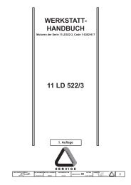
code 1.5302.711<br />
Wor<br />
orkshop Manual
REGISTRATION OF MODIFICATIONS TO THE DOCUMENT<br />
This document consists of 108 pages (sides -excluding the cover<br />
and title page). Each page is numbered in progressive order<br />
from 050530.01 to 050530.108.<br />
Any modifications to this document must be registered by the<br />
drafting body and approved by the head of the<br />
Quality Management System, by completing the<br />
following table.<br />
Drafting body<br />
Document<br />
code<br />
Edition<br />
Issue date<br />
Review<br />
date<br />
Replaced<br />
pages<br />
Added<br />
pages<br />
Eliminated<br />
pages<br />
ATLO 1-5302-711 1° 26-04-2007<br />
- 2 - Service Manual LGW 523 MPI automotive _ cod. 1.5302.711 - 1° ed_rev. 00
1 GENERAL REMARKS AND SAFETY<br />
INFORMATION<br />
1.1 PURPOSE OF THE MANUAL .................................. 5<br />
1.2 USING THIS MANUAL ............................................. 5<br />
1.3 MANUFACTURER AND ENGINE<br />
IDENTIFICATION ..................................................... 5<br />
1.4 GLOSSARY AND TERMINOLOGY ........................... 6<br />
1.5 WARRANTY CLAUSES ............................................ 6<br />
1.6 GENERAL SAFETY REGULATIONS ....................... 6<br />
1.7 GENERAL SAFETY DURING OPERATION ............ 6<br />
1.8 SAFETY AND ENVIRONMENTAL IMPACT .............. 7<br />
1.9 PRECAUTIONS WHEN THE ENGINE<br />
IS INSTALLED ON THE VEHICLE ......................... 7<br />
1.10 PRECAUTIONS WHEN THE ENGINE<br />
IS ON THE ROTATING STAND ............................... 7<br />
2 TECHNICAL INFORMATION<br />
2.1 GENERAL DESCRIPTION OF THE ENGINE ......... 9<br />
2.2 TECHNICAL SPECIFICATIONS ............................10<br />
2.3 PERFORMANCE CURVE DIAGRAM ..................... 12<br />
2.4 ALTERNATOR LOAD CURVE DIAGRAMS ............13<br />
2.5 LUBRICANTS ........................................................14<br />
2.6 COOLANT ..............................................................15<br />
2.7 FUEL SPECIFICATIONS ....................................... 15<br />
2.8 ROUTINE MAINTENANCE OF<br />
LGW 523 MPI ENGINE ..........................................15<br />
2.9 OPERATING PRINCIPLE FOR LUBRICATION ....16<br />
2.10 OPERATING PRINCIPLE FOR COOLING ............16<br />
2.11 OPERATING PRINCIPLE FOR FUEL SUPPLY ....17<br />
2.12 WIRING DIAGRAM .................................................18<br />
2.13 ELECTRONIC ENGINE CONTROL<br />
WIRING DIAGRAM ................................................20<br />
2.14 ELECTRICAL WIRING FOR ELECTRONIC<br />
ENGINE CONTROL ...............................................21<br />
2.15 FUEL SUPPLY SYSTEM ........................................22<br />
2.15.1 Electric fuel supply pump ......................................22<br />
2.15.2 Fuel filter ................................................................22<br />
2.15.3 Pressure regulator ................................................22<br />
2.15.4 Prefilter...................................................................22<br />
2.15.5 Injector supply pipe ...............................................23<br />
2.15.6 Injectors .................................................................23<br />
2.15.7 Inertial switch ......................................................... 23<br />
2.16 ELECTRONIC ENGINE CONTROL SYSTEM .......24<br />
2.16.1 Ignition coil .............................................................25<br />
2.16.2 Spark plug .............................................................25<br />
2.16.3 Lambda probe sensor ..........................................25<br />
2.16.4 Electronic control unit (E.C.U.) ..............................26<br />
2.16.5 Control unit identification plate .............................26<br />
2.16.6 Speed sensor ........................................................26<br />
2.16.7 Air temperature sensor .........................................27<br />
2.16.8 Absolute pressure sensor ....................................27<br />
2.16.9 Water temperature sensor ....................................27<br />
2.16.10 Throttle control sensor ..........................................28<br />
2.16.11 Throttle body ..........................................................28<br />
2.17 INTAKE SYSTEM ....................................................29<br />
2.18 EXHAUST SYSTEM ................................................29<br />
2.19 SPECIAL TOOLS AND EQUIPMENT<br />
FOR MAINTENANCE ............................................30<br />
2.20 TIGHTENING TORQUE TABLES ..........................30<br />
2.20.1 Table of tightening torques for standard<br />
screws (coarse thread) .........................................30<br />
2.20.2 Table of tightening torques for standard<br />
screws (fine thread) .............................................. 31<br />
2.20.3 Table of tightening torques for the<br />
main components .................................................31<br />
2.21 TABLE OF SEALANTS ...........................................32<br />
3 MALFUNCTIONS<br />
3.1 TABLE OF LIKELY ANOMALIES<br />
AND THEIR SYMPTOMS ........................................ 33<br />
4 STORING THE ENGINE<br />
4.1 HANDLING AND LIFTING .....................................35<br />
4.2 ENGINE STORAGE (UNINSTALLED) ...................35<br />
4.3 ENGINE STORAGE (INSTALLED) ........................35<br />
4.4 PROTECTIVE TREATMENT .................................. 36<br />
4.5 PREPARING THE ENGINE FOR<br />
OPERATION AFTER PROTECTIVE<br />
TREATMENT ..........................................................36<br />
5 REMOVING THE ASSEMBLIES<br />
5.1 RECOMMENDATIONS FOR REMOVING<br />
THE ASSEMBLIES .................................................37<br />
5.2 REMOVING THE EXHAUST AND<br />
INTAKE MANIFOLDS ............................................. 37<br />
5.2.1 Disassembling the intake manifold ..................... 37<br />
5.2.2 Disassembling the air flow sensors ....................40<br />
5.2.3 Disassembling the exhaust manifold ..................40<br />
5.3 REMOVING THE COOLING FAN BELT DRIVE .....41<br />
5.3.1 Disassembling the cooling fan belt<br />
(with external alternator) ........................................ 42<br />
5.3.2 Disassembling the cooling fan belt<br />
(with internal alternator) ........................................ 42<br />
5.4 REMOVING THE TIMING BELT DRIVE .................43<br />
5.4.1 Disassembling the timing belt guard ...................43<br />
5.4.2 Timing belt and gears ...........................................43<br />
5.4.3 Removing the speed sensor ................................44<br />
5.4.4 Disassembling the synchronous timing belt.......44<br />
5.4.5 Sliding pulley and belt tightener ........................... 44<br />
5.4.6 Disassembling the synchronous timing<br />
belt pulleys (camshaft and crankshaft) ................ 45<br />
5.4.7 Disassembling the coolant circulation pump ......45<br />
5.4.8 Disassembling the pump scroll ........................... 46<br />
5.5 REMOVING THE CYLINDER HEAD<br />
AND COMPONENTS ............................................. 46<br />
5.5.1 Disassembling the spark plug .............................46<br />
5.5.2 Disassembling the rocker arm cover ...................47<br />
5.5.3 Disassembling the rocker arm assembly ...........47<br />
5.5.4 Disassembling the injectors ................................48<br />
5.5.5 Disassembling the camshaft ...............................50<br />
5.5.6 Disassembling the thermostatic valve body ........50<br />
5.5.7 Removing the cylinder head ................................. 51<br />
5.6 DISASSEMBLING THE VALVES ............................ 51<br />
5.7 REMOVING THE CRANK GEAR AND<br />
CRANKCASE ......................................................... 52<br />
5.7.1 Disassembling the flywheel ................................. 52<br />
5.7.2 Disassembling the oil pump ................................52<br />
5.7.3 Disassembling the crankcase and crankshaft .... 53<br />
5.7.4 Disassembling the connecting rod and piston ... 54<br />
5.8 DISASSEMBLING THE PISTON ............................ 54<br />
Service Manual LGW 523 MPI automotive _ cod. 1.5302.711 - 1° ed_rev. 00<br />
- 3 -
6 OVERHAULS AND TUNING<br />
6.1 RECOMMENDATIONS FOR OVERHAULS<br />
AND TUNING .........................................................57<br />
6.1.1 Shaft seals .............................................................57<br />
6.1.2 O-rings ...................................................................57<br />
6.1.3 Bearings ................................................................57<br />
6.2 OVERHAULING THE CRANK GEARS<br />
AND CRANKCASE .................................................57<br />
6.2.1 Overhauling cylinders and pistons .......................57<br />
6.2.2 Dimensional check and overhaul of cylinders .....58<br />
6.2.3 Dimensional check and overhaul of pistons .......58<br />
6.2.4 Dimensional check of sealing rings ....................59<br />
6.2.5 Dimensional check and overhaul of crankshaft ..60<br />
6.2.6 Dimensional check and overhaul<br />
of connecting rods .................................................61<br />
6.2.7 Checking parallelism of the connecting<br />
rod axes .................................................................61<br />
6.2.8 Checking and overhauling the oil pump ..............62<br />
6.2.9 Overhauling the decanting device ........................63<br />
6.3 OVERHAULING THE CYLINDER HEAD<br />
AND COMPONENTS .............................................63<br />
6.3.1 Checking and overhauling the cylinder head .......63<br />
6.3.2 Checking and overhauling the valves ...................64<br />
6.3.3 Checking and overhauling the rocker arm pin .....65<br />
6.3.4 Hydraulic tappets ..................................................66<br />
6.3.5 Checking and replacing the camshaft .................68<br />
6.4 DIAGRAM OF TIMING BELT RATES ......................69<br />
6.5 CHECKING THE SPARK PLUG ............................69<br />
6.6 REPLACING THE FLYWHEEL RING GEAR .........70<br />
7 INSTALLATION OF ASSEMBLIES<br />
7.1 RECOMMENDATIONS FOR<br />
INSTALLING ASSEMBLIES ...................................71<br />
7.2 INSTALLING VALVES ............................................71<br />
7.2.1 Assembling the valves ..........................................71<br />
7.3 PREASSEMBLY OF SEALING<br />
RINGS - PISTONS ................................................72<br />
7.4 PRE-ASSEMBLY OF CONNECTING<br />
RODS – PISTONS .................................................73<br />
7.5 INSTALLATION OF CRANK GEAR<br />
AND CRANKCASE .................................................73<br />
7.5.1 Installing piston/connecting rod - engine block ...73<br />
7.5.2 Assembling the crankshaft ...................................74<br />
7.5.3 Assembling the crankcase ...................................75<br />
7.5.4 Checking crankshaft axial clearance ...................75<br />
7.5.5 Assembling the crankshaft flange<br />
(flywheel side) .......................................................76<br />
7.5.6 Installing the pump scroll .....................................76<br />
7.5.7 Installing the coolant circulation pump ................77<br />
7.5.8 Assembling the oil pump ......................................77<br />
7.5.9 Assembling the flywheel .......................................78<br />
7.5.10 Determining clearance volume ............................79<br />
7.6 INSTALLATION OF CYLINDER HEAD<br />
AND COMPONENTS ............................................ 80<br />
7.6.1 Assembling the cylinder head ..............................80<br />
7.6.2 Assembling the camshaft .....................................80<br />
7.6.3 Installing the camshaft support and<br />
timing belt pulley ...................................................81<br />
7.6.4 Installing the rocker arm assembly ......................81<br />
7.6.5 Installing the rocker arm cover .............................81<br />
7.6.6 Installing the spark plug ........................................82<br />
7.6.7 Installing the injectors ...........................................82<br />
7.6.8 Installing the thermostatic valve body ..................83<br />
7.7 INSTALLATION OF THE TIMING BELT DRIVE .....84<br />
7.7.1 Assembling the phase sensor .............................84<br />
7.7.2 Assembling the timing belt pulleys<br />
(camshaft and crankshaft) ....................................85<br />
7.7.3 Adjusting the phase sensor ..................................85<br />
7.7.4 Assembling the synchronous timing belt ............85<br />
7.7.5 Assembling the timing belt guard ........................86<br />
7.8 INSTALLATION OF THE COOLING<br />
FAN BELT DRIVE ................................................... 87<br />
7.8.1 Assembling the cooling fan belt drive pulleys .....87<br />
7.8.2 Assembling the cooling fan belt<br />
(with internal alternator) ........................................88<br />
7.8.3 Assembling the cooling fan belt<br />
(with external alternator) ........................................89<br />
7.9 INSTALLATION OF THE EXHAUST<br />
AND INTAKE MANIFOLDS .....................................90<br />
7.9.1 Assembling the throttle and sensors ...................90<br />
7.9.2 Assembling the intake manifold ........................... 90<br />
7.9.3 Assembling the exhaust manifold ........................92<br />
8 VEHICLE CONTROLS<br />
8.1 VEHICLE CONTROLS ...........................................95<br />
8.1.1 Preliminary checks ................................................95<br />
8.2 COMPONENTS LAYOUT<br />
INSIDE THE ENGINE CASE ..................................95<br />
8.2.1 Petrol pressure check ...........................................96<br />
8.2.2 Injector check ......................................................... 96<br />
8.2.3 Adjusting the accelerator cable ............................97<br />
8.3 DIAGNOSTIC ......................................................... 98<br />
8.3.1 Using the diagnostic procedures .........................98<br />
8.3.2 Technical features .................................................98<br />
8.3.3 Total view of the tool ..............................................98<br />
8.3.4 Accessories ...........................................................99<br />
8.3.5 Autodiagnostic software ........................................99<br />
8.4 PRELIMINARY OPERATIONS ............................ 100<br />
8.4.1 Connecting to the vehicle ................................... 100<br />
8.4.2 Vehicle and system selection............................ 100<br />
8.5 AVAILABLE FUNCTIONS FOR DIAGNOSTIC ... 102<br />
8.5.1 Autodiagnostic .................................................... 102<br />
8.5.2 Detecting faults ................................................... 102<br />
8.5.3 Menu bar ............................................................. 103<br />
8.5.4 Important to be pointed out before starting ....... 103<br />
8.6 ERRORS ............................................................. 104<br />
8.7 CONSTRUCTION PARAMETERS ...................... 105<br />
- 4 - Service Manual LGW 523 MPI automotive _ cod. 1.5302.711 - 1° ed_rev. 00
GENERAL REMARKS AND SAFETY INFORMATION<br />
1<br />
1.1 PURPOSE OF THE MANUAL<br />
- This manual was written by the manufacturer to<br />
provide technical and operating information to<br />
authorised LOMBARDINI after-sales <strong>service</strong> centres<br />
to carry out assembly, disassembly,overhauling,<br />
replacement and tuning operations.<br />
- This information is provided by the manufacturer in<br />
its own language (Italian) and may be translated into<br />
other languages to satisfy legislative and/or<br />
commercial requirements.<br />
- As well as employing good operating techniques and<br />
observing the right timing for operations, operators<br />
must read the information very carefully and comply<br />
with it scrupulously.<br />
- Time spent reading this information will help to<br />
prevent health and safety risks and financial damage.<br />
Written information is accompanied by illustrations<br />
in order to facilitate your understanding of every step<br />
of the operating phases.<br />
- Important remarks and features of the text are<br />
highlighted using symbols, which are explained<br />
below.<br />
Danger – Attention<br />
This indicates situations of grave danger which, if<br />
ignored, may seriously threaten the health and<br />
safety of individuals.<br />
Caution – Warning<br />
This indicates that it is necessary to take proper<br />
precautions to prevent any risk to the health and<br />
safety of individuals and avoid financial damage.<br />
Important<br />
This indicates particularly important technical<br />
information that should not be ignored.<br />
1.2 USING THIS MANUAL<br />
- This manual is divided into several chapters.<br />
- The first chapter gives general information and details<br />
about safety (purpose of the manual, safety, etc.).<br />
- The second, third and fourth chapters provide general<br />
technical information (technical specifications,<br />
diagrams, tightening torques, malfunctions, etc.).<br />
- The fifth, sixth, seventh and eighth chapters describe<br />
the most important operating procedures (removal,<br />
overhaul and tuning, installation, replacements, etc.).<br />
- This final section, which is reserved specifically for<br />
LOMBARDINI after-sales <strong>service</strong> centres, has been<br />
prepared with technical and practical considerations<br />
in mind.<br />
- However, the actual sequence of operations that<br />
LOMBARDINI <strong>service</strong> centres use may in some<br />
cases be different from the ones described in this<br />
manual. For this reason, readers should refer to the<br />
index to find their topic of interest quickly.<br />
1.3 MANUFACTURER AND ENGINE IDENTIFICATION<br />
The identification plate shown in the figure<br />
can be found directly on the engine. It<br />
contains the model, engine identity and all<br />
information needed to operate safely.<br />
A) Manufacturer’s identity<br />
B) Engine type<br />
C) Engine serial number<br />
D) Maximum operating speed<br />
E) Number of the customer version (form K)<br />
Service Manual LGW 523 MPI automotive _ cod. 1.5302.711 - 1° ed_rev. 00<br />
- 5 -
General remarks and safety information<br />
1<br />
1.4 GLOSSARY AND TERMINOLOGY<br />
For clarity, here are the definitions of a number of terms<br />
used recurrently in the manual.<br />
- Cylinder number one: first piston «viewed from the<br />
flywheel side of the engine».<br />
- Rotation direction: clockwise or anticlockwise<br />
«viewed from the timing belt side of the engine».<br />
1.5 WARRANTY CLAUSES<br />
LOMBARDINI issues a warranty certificate for each<br />
engine giving details of all relevant general terms.<br />
1.6 GENERAL SAFETY REGULATIONS<br />
- In designing and building its product, the<br />
manufacturer has paid particular attention to those<br />
aspects that pose a risk to the health and safety of<br />
persons handling the engine. In addition to legislative<br />
requirements, all «rules for good technical<br />
construction» have been applied.<br />
- The purpose of this information is to invite operators<br />
to pay particular attention in order to prevent any<br />
form of risk. Caution is always the best policy.<br />
Safety is also the responsibility of all operators who<br />
handle the engine.<br />
- All persons carrying out work on the engine at any<br />
point in its life, must possess precise technical<br />
qualifications and skills, as well as recognised<br />
experience gained in the specific sector. Noncompliance<br />
with these requirements may cause<br />
damage to the health and safety of individuals.<br />
- Do not tamper with, sidestep, eliminate or bypass the<br />
installed safety devices. Non-compliance with this<br />
requirement may be hazardous to the health and<br />
safety of individuals.<br />
1.7 GENERAL SAFETY DURING OPERATING PHASES<br />
- The procedures contained in this manual have been<br />
tested and selected by the manufacturer’s technical<br />
experts, and hence are to be recognised as<br />
authorised operating methods.<br />
- A number of procedures must be carried out with the<br />
aid of equipment and tools that simplify and improve<br />
the timing of operations.<br />
- Some of these tools are normal workshop equipment,<br />
while others are specific instruments that have been<br />
constructed by the engine manufacturer.<br />
- All tools must be in good working condition so that<br />
engine components are not damaged and that<br />
operations are carried out properly and safely.<br />
It is important to wear the personal safety devices<br />
prescribed by work safety laws and also by the<br />
standards of this manual.<br />
- Holes must be lined up methodically and with the aid<br />
of suitable equipment. Do not use your fingers to<br />
carry out this operation to avoid the risk of<br />
amputation.<br />
- Some phases may require the assistance of more<br />
than one operator. If so, it is important to inform and<br />
train them regarding the type of activity they will be<br />
performing in order to prevent risks to the health and<br />
safety of all persons involved.<br />
- Do not use flammable liquids (petrol, diesel, etc.) to<br />
degrease or wash components. Use special products.<br />
- Keep flames away from the engine to avoid the risk of<br />
fire.<br />
- Replace worn or damaged parts exclusively with<br />
original LOMBARDINI spare parts. This will<br />
contribute to ensuring better performance and longer<br />
product life.<br />
- Use the oils and greases recommended by the<br />
manufacturer.<br />
Do not mix different brands or combine oils with<br />
different characteristics.<br />
- Use a torque wrench to tighten the main fixing points<br />
of engine components. Comply with the tightening<br />
torques indicated by the manufacturer.<br />
- Discontinue use of the engine if any irregularities<br />
arise, particularly in the case of unusual vibrations.<br />
- The engine has been designed and built to satisfy all<br />
the operating conditions described by the<br />
manufacturer.<br />
- Do not tamper with any devices to alter the level of<br />
performance guaranteed by the manufacturer.<br />
- 6 - Service Manual LGW 523 MPI automotive _ cod. 1.5302.711 - 1° ed_rev. 00
General remarks and safety information<br />
1<br />
1.8 SAFETY AND ENVIRONMENTAL IMPACT<br />
Every organisation has a duty to implement procedures<br />
to identify, assess and monitor the influence of its own<br />
activities (products, <strong>service</strong>s, etc.) on the environment.<br />
Procedures for identifying the extent of the impact on<br />
the environment must consider the following factors:<br />
- Liquid waste<br />
- Waste management<br />
- Soil contamination<br />
- Atmospheric emissions<br />
- Use of raw materials and natural resources<br />
- Regulations and directives regarding environmental<br />
impact<br />
In order to minimise the impact on the environment, the<br />
manufacturer now provides a number of indications to be<br />
followed by all persons handling the engine, for any<br />
reason, during its expected lifetime.<br />
- All packaging components must be disposed of in<br />
accordance with the laws of the country in which<br />
disposal is taking place.<br />
- Keep the fuel and engine control systems and the<br />
exhaust pipes in efficient working order to limit<br />
environmental and noise pollution.<br />
- When discontinuing use of the engine, select all<br />
components according to their chemical<br />
characteristics and dispose of them separately.<br />
1.9 PRECAUTIONS WHEN THE ENGINE IS INSTALLED ON THE VEHICLE<br />
- All operations, except where expressly stated<br />
otherwise, must be carried out when the engine is<br />
not running and has cooled sufficiently to avoid the<br />
risk of burns.<br />
- Do not keep the engine running in areas that are<br />
closed and inadequately ventilated. Take all<br />
necessary precautions to prevent a build up of<br />
exhaust fumes.<br />
1.10 PRECAUTIONS WHEN THE ENGINE IS ON THE ROTATING STAND<br />
- Before removing the engine from the vehicle on which<br />
it is installed, disconnect the electric current, the<br />
fuel supply, coolant and all connections including<br />
mechanical ones.<br />
- To lift the engine, attach the lifting device at the<br />
points (eyebolts) specified by the manufacturer.<br />
- Close all engine openings carefully (exhaust, intake,<br />
etc.) wash the outside and dry with a jet of<br />
compressed air.<br />
- Anchor the engine to the rotating stand to facilitate all<br />
operations.<br />
Note: the engine may also be placed on the<br />
workbench, depending on the type of work to be<br />
carried out.<br />
Service Manual LGW 523 MPI automotive _ cod. 1.5302.711 - 1° ed_rev. 00<br />
- 7 -
General remarks and safety information<br />
1<br />
Notes :<br />
. ..........................................................................................................................................................................<br />
. ..........................................................................................................................................................................<br />
. ..........................................................................................................................................................................<br />
. ..........................................................................................................................................................................<br />
...........................................................................................................................................................................<br />
. ..........................................................................................................................................................................<br />
. ..........................................................................................................................................................................<br />
. ..........................................................................................................................................................................<br />
. ..........................................................................................................................................................................<br />
. ..........................................................................................................................................................................<br />
. ..........................................................................................................................................................................<br />
. ..........................................................................................................................................................................<br />
. ..........................................................................................................................................................................<br />
...........................................................................................................................................................................<br />
. ..........................................................................................................................................................................<br />
. ..........................................................................................................................................................................<br />
. ..........................................................................................................................................................................<br />
. ..........................................................................................................................................................................<br />
. ..........................................................................................................................................................................<br />
. ..........................................................................................................................................................................<br />
. ..........................................................................................................................................................................<br />
. ..........................................................................................................................................................................<br />
...........................................................................................................................................................................<br />
. ..........................................................................................................................................................................<br />
. ..........................................................................................................................................................................<br />
. ..........................................................................................................................................................................<br />
. ..........................................................................................................................................................................<br />
. ..........................................................................................................................................................................<br />
. ..........................................................................................................................................................................<br />
...........................................................................................................................................................................<br />
...........................................................................................................................................................................<br />
- 8 - Service Manual LGW 523 MPI automotive _ cod. 1.5302.711 - 1° ed_rev. 00
TECHNICAL INFORMATION<br />
2<br />
2.1 GENERAL DESCRIPTION OF THE ENGINE<br />
Main components<br />
1) Cylinder head<br />
2) Engine block 10) Alternator<br />
3) Crankcase 11) Oil filter<br />
4) Timing assembly 12) Exhaust manifold and thermal protection<br />
5) Flywheel and crankshaft assembly 13) Starter motor<br />
6) Air intake assembly 14) Dipstick<br />
7) Throttle body 15) Thermostatic valve body<br />
8) Cooling fan 16) Tappet cover<br />
9) Breather circuit 17) Engine anchor points (Eye bolts)<br />
Description<br />
- Four-stroke petrol engine, two in-line cylinders<br />
- Cylinder block and head in aluminium alloy.<br />
- Timing system with two valves per cylinder regulated<br />
by overhead camshaft driven by toothed belt,<br />
hydraulic tappets for automatic valve clearance<br />
adjustment.<br />
- Timed sequential indirect multipoint fuel injection,<br />
with motorised drive-by-wire throttle and Lambda<br />
exhaust probe. Integrated injection and ignition<br />
control.<br />
- Forced lubrication by crankshaft-driven oil pump.<br />
- Cooling by forced liquid circulation.<br />
Approval<br />
- Able to satisfy pollution limits set by 2002/51/EC for<br />
vehicles belonging to the category of «quadricycles».<br />
Service Manual LGW 523 MPI automotive _ cod. 1.5302.711 - 1° ed_rev. 00<br />
- 9 -
Technical information<br />
2<br />
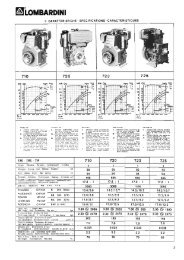
2.2. TECHNICAL SPECIFICATIONS<br />
(1)(2)<br />
A<br />
372,9<br />
D<br />
163,5<br />
DIMENSIONS (mm)<br />
H 37<br />
P<br />
145<br />
R<br />
182<br />
B<br />
C<br />
484,2<br />
480,7<br />
E<br />
G<br />
180,1<br />
209,4<br />
M<br />
N<br />
280<br />
339,2<br />
Q<br />
45,5 ( 1 )<br />
58 ( 2 )<br />
S<br />
T<br />
160<br />
91,5<br />
(1) with intake fan<br />
(2) with exhaust fan<br />
GENERAL DETAILS<br />
Operating cycle<br />
Cylinders<br />
Bore x stroke<br />
Displacements<br />
Compression rate<br />
Intake<br />
Cooling<br />
Crankshaft rotation<br />
Combustion sequence<br />
Timing system<br />
Valves<br />
Shaft<br />
Tappets<br />
Fuel injection<br />
Dry weight of engine<br />
Volume of air flow (at 5,000 RPM)<br />
Volume of cooling air (at 5,000 RPM)<br />
POWER AND TORQUE<br />
Maximum operating speed<br />
Max. power (N 80/1269/EEC - ISO 1585 - DIN 7020)<br />
Maximum torque (at 2150 RPM)<br />
Axial load allowed on crankshaft<br />
Four-stroke petrol<br />
n°<br />
2 in line<br />
mm<br />
72x62<br />
cm 3<br />
505<br />
10,7:1<br />
Dry air filter<br />
Liquid<br />
Clockwise (from timing system side)<br />
1:2<br />
Synchronous toothed belt<br />
n° 2 per cylinder<br />
overhead camshaft<br />
hydraulic<br />
indirect sequential multipoint<br />
Kg 52<br />
l/min<br />
910<br />
m 3 /min<br />
36<br />
RPM<br />
kW<br />
Nm<br />
Kg<br />
5500<br />
15 *<br />
34<br />
300<br />
* Self-limiting power for quadricycle applications.<br />
- 10 - Service Manual LGW 523 MPI automotive _ cod. 1.5302.711 - 1° ed_rev. 00
Technical information<br />
2<br />
FUEL SUPPLY CIRCUIT<br />
Fuel type<br />
Fuel supply<br />
Fuel filter<br />
Unleaded petrol min. 95 RON<br />
Electric pump<br />
in line<br />
Filter capacity<br />
Circuit pressure<br />
µm<br />
bar<br />
8÷10<br />
3,5<br />
LUBRICATION CIRCUIT<br />
Type of lubrication<br />
Circuit supply<br />
Maximum oil quantity<br />
Maximum oil quantity<br />
Completely forced<br />
Trochoid pump<br />
including filter (l)<br />
excluding filter (l)<br />
1,3<br />
1,2<br />
Oil pressure at minimum speed (with oil temperature of 120°C)<br />
Oil filter cartridge<br />
Maximum operating pressure<br />
Maximum combustion pressure<br />
Filter capacity<br />
By-pass valve setting<br />
Filtering surface<br />
no lower than 1 bar<br />
bar<br />
bar<br />
µm<br />
bar<br />
cm 2 7<br />
20<br />
15<br />
1,5÷1,7<br />
730<br />
COOLING CIRCUIT<br />
Coolant<br />
50% water - 50% liquid anti-freeze liquid<br />
Thermostatic valve<br />
Opening temperature<br />
Stroke at 94°C<br />
Liquid return<br />
°C<br />
mm<br />
l/h<br />
78°÷82°<br />
7<br />
30÷80<br />
ELECTRICAL SYSTEM<br />
Nominal voltage<br />
Alternator (nominal voltage)<br />
Internal/external alternator (nominal current)<br />
(see «Alternator load curve diagrams»)<br />
Starter motor power<br />
Oil pressure switch<br />
Operating pressure bars<br />
Coolant temperature monitoring sensor<br />
V<br />
V<br />
A<br />
kW<br />
bar<br />
12<br />
14<br />
40<br />
1,1<br />
0,45÷0,75<br />
Electrical circuit<br />
Unipolar system<br />
Supply voltage<br />
Absorbed power<br />
Closed circuit temperature<br />
V<br />
W<br />
°C<br />
6÷24<br />
3<br />
97°÷103°<br />
Service Manual LGW 523 MPI automotive _ cod. 1.5302.711 - 1° ed_rev. 00<br />
- 11 -
Technical information<br />
2<br />
2.3 PERFORMANCE DIAGRAM<br />
Legend<br />
N* (80/1269/EEC-ISO 1585) = Power curve. Automotive power: discontinuous <strong>service</strong>s at variable RPM and load.<br />
MN* = Torque curve<br />
C* = specific consumption curve<br />
* The above curves are approximate since they depend on the intake and exhaust systems in use and on engine<br />
mapping<br />
The above power levels refer to the engine equipped with air filter, muffler, fully broken-in suction fan, and ambient<br />
conditions of 20°C and 1 bar.<br />
The maximum power is guaranteed with a tolerance of 5%.<br />
These power rates are reduced by approx. 1% every 100m of altitude and by 2% for every 5°C exceeding 25°C.<br />
Note:<br />
Please contact Lombardini for power, torque, and specific consumption curves at different speeds from the above.<br />
Caution – Warning<br />
Please remember that any variation in the intake or exhaust system during the application phase of LGW<br />
523 engines involves a variation in fuel.<br />
Optimisation must be carried out beforehand at Lombardini testing centres.<br />
Non-approval by Lombardini for any modifications releases the company from any damages incurred by the<br />
engine.<br />
- 12 - Service Manual LGW 523 MPI automotive _ cod. 1.5302.711 - 1° ed_rev. 00
Technical information<br />
2<br />
2.4 ALTERNATOR LOAD CURVE DIAGRAMS<br />
Reading taken after heat stabilisation at 25°C and<br />
constant voltage 14V.<br />
External 40A alternator load curve diagram<br />
Current supplied (A)<br />
Alternator RPM<br />
Internal 30A alternator load curve diagram<br />
Internal 40A alternator load curve diagram<br />
Current supplied (A)<br />
Current supplied (A)<br />
Alternator RPM<br />
Alternator RPM<br />
Reading taken after heat stabilisation at 20°C and<br />
constant voltage 12.5V.<br />
* The alternator turns at the same rate as the engine.<br />
Service Manual LGW 523 MPI automotive _ cod. 1.5302.711 - 1° ed_rev. 00<br />
- 13 -
Technical information<br />
2<br />
2.5 LUBRICANTS<br />
SAE classification<br />
In the SAE classification oils are identified<br />
according to viscosity without considering any<br />
other qualitative characteristic.<br />
The first number refers to the viscosity when cold,<br />
for use during winter (W= winter), while the<br />
second number is for viscosity at high<br />
temperatures. The criteria for choosing an oil<br />
must include the minimum ambient temperature<br />
to which the engine is to be exposed during the<br />
winter and the maximum temperature during<br />
operation in the summer.<br />
Monograde oils are generally used when the<br />
operating temperature varies little.<br />
Multigrade oils are less sensitive to temperature<br />
variations.<br />
- - - - - - - -<br />
40 35 30 25 20 15 10 5 0<br />
SAE 10W*<br />
+<br />
5<br />
SAE 20W*<br />
SAE 10W-30**<br />
SAE 30*<br />
SAE 10W-40**<br />
SAE 10W-60**<br />
SAE 15W-40 **<br />
SAE 15W-40 **<br />
SAE 40*<br />
SAE 20W-60 **<br />
SAE 5W-30 ***<br />
SAE 5W-40 ***<br />
SAE 0W-30 ***<br />
+ + + + + + + +<br />
10 15 20 25 30 35 40 45<br />
+<br />
50<br />
* Mineral base<br />
** Semi-synthetic base<br />
*** Synthetic base<br />
API/MIL Sequences<br />
DIESEL<br />
PETROL<br />
1234567890123456789012<br />
123456789012345678<br />
1234567890123456781234567890123456789012<br />
API CH-4 CG-4 CF-4 CF-2 CF CE CD CC CB CA SA SB SC SD SE SF SG SH SJ SL<br />
1234567890123456781234567890123456789012<br />
123456789012345678 1234567890123456789012<br />
1234567890123456781234567890123456789012<br />
MIL<br />
L - 2104 D / E<br />
L - 46152 B / C / D / E<br />
CORRENTI - CURRENT<br />
123456789012345678<br />
123456789012345678<br />
OBSOLETI-OBSOLETE<br />
123456789012345678<br />
Key to abbreviations<br />
A.P.I.<br />
MIL<br />
ACEA<br />
: (American Petroleum Institute)<br />
: USA military specifications for engine oils issued for logistics reasons<br />
: European Automobile Manufacturers Association<br />
ACEA Standards – ACEA sequences<br />
PETROL<br />
A1 = Low-viscosity, for friction reduction<br />
A2 = Standard<br />
A3 = High performance<br />
LIGHT DIESELS<br />
B1 = Low-viscosity, for friction reduction<br />
B2 = Standard<br />
B3 = High performance (indirect injection)<br />
B4 = High quality (direct injection)<br />
HEAVY DIESELS<br />
E1 = Obsolete<br />
E2 = Standard<br />
E3 = Heavy conditions (Euro 1 - Euro 2 engines)<br />
E4 = Heavy conditions (Euro 1 - Euro 2 - Euro 3<br />
engines)<br />
E5 = High performance in heavy conditions (Euro 1 -<br />
Euro 2 - Euro 3 engines)<br />
- 14 - Service Manual LGW 523 MPI automotive _ cod. 1.5302.711 - 1° ed_rev. 00
Technical information<br />
2<br />
Recommended oil<br />
Description Oil type Oil characteristics<br />
Engine<br />
oil<br />
Agip SINT<br />
2000 5W40<br />
API SJ/CF ACEA<br />
A3-96 B3-96<br />
MIL-L-4615 D/E<br />
Engine oil capacity<br />
Oil volume at max. level<br />
(including oil filter)<br />
Oil volume at max. level<br />
(without filter)<br />
Litres<br />
Litres<br />
1,3<br />
1,2<br />
2.6 COOLANT<br />
The use of anti-freeze protection liquid (e.g. AGIP ANTIFREEZE) is recommended mixed with water, preferably<br />
decalcified.<br />
The freezing point of the cooling mixture depends on the product concentration in water:<br />
at -15°C (30%), at -20°C (35%), at -25°C (40%), at -30°C (45%), at -35°C (50%).<br />
It is therefore recommended to use a 50% diluted mixture which guarantees a certain degree of overall protection.<br />
As well as lowering the freezing point, the permanent liquid also raises the boiling point.<br />
2.7 FUEL SPECIFICATIONS<br />
Unleaded petrol min. 95 RON.<br />
2.8 ROUTINE ENGINE MAINTENANCE – LGW 523 MPI<br />
Important<br />
Non-compliance with the operations described in<br />
the table may lead to technical damage to the<br />
engine and vehicle, and furthermore, releases the<br />
manufacturer from the warranty obligations.<br />
Important<br />
Even if the set mileage has not been reached, the<br />
following must nevertheless be replaced:<br />
- engine oil after one year<br />
- coolant after two years<br />
- fan/alternator belt after four years<br />
- timing belt after four years<br />
PROCEDURE<br />
CHECK<br />
CHANGE<br />
DETAIL<br />
ENGINE OIL<br />
COOLANT LEVEL<br />
COOLING SYSTEM<br />
ALTERNATOR/FAN BELT TENSION<br />
AIR FILTER<br />
FUEL PIPES AND UNIONS<br />
EXHAUST SYSTEM<br />
ENGINE OIL<br />
OIL FILTER<br />
FUEL FILTER<br />
AIR FILTER CARTRIDGE<br />
ALTERNATOR/FAN BELT<br />
SPARK PLUGS<br />
COOLANT<br />
TIMING BELT(*)<br />
REGULARITY per 1000km<br />
1 10 20 30 40 50 60 70 80 90 100<br />
EVERY 2.500 Km<br />
EVERY 2.500 Km<br />
(*) Replace the timing belt whenever it is removed, even if has not completed its scheduled motion time.<br />
Maintain the same maintenance intervals above 100,000 km.<br />
Service Manual LGW 523 MPI automotive _ cod. 1.5302.711 - 1° ed_rev. 00<br />
- 15 -
Technical information<br />
2<br />
2.9 OPERATING PRINCIPLE FOR LUBRICATION<br />
Réf.<br />
1<br />
2<br />
3<br />
4<br />
5<br />
6<br />
7<br />
8<br />
9<br />
10<br />
11<br />
12<br />
13<br />
14<br />
15<br />
Description<br />
Pressure switch<br />
Rocker arm pin<br />
Connecting rod big end pin<br />
Oil filter cartridge<br />
Main journal<br />
Oil drain plug<br />
Dipstick<br />
Breather pipe<br />
Oil refill plug<br />
Camshaft<br />
Oil pressure adjustment valve<br />
Oil pump<br />
Crankshaft<br />
Oil suction filter<br />
Hydraulic tappet<br />
2.10 OPERATING PRINCIPLE FOR COOLING<br />
Réf.<br />
1<br />
2<br />
3<br />
4<br />
5<br />
6<br />
7<br />
8<br />
Description<br />
Coolant refill plug<br />
Compensation tank<br />
Thermostatic valve<br />
Cylinder block<br />
Liquid temperature monitoring thermostat<br />
Circulation pump<br />
Fan<br />
Radiator<br />
- 16 - Service Manual LGW 523 MPI automotive _ cod. 1.5302.711 - 1° ed_rev. 00
Technical information<br />
2<br />
2.11 OPERATING PRINCIPLE FOR FUEL SUPPLY<br />
1<br />
10<br />
4<br />
3<br />
8<br />
5<br />
2<br />
9<br />
7<br />
11<br />
6<br />
11<br />
9<br />
7<br />
Réf.<br />
1<br />
2<br />
3<br />
4<br />
5<br />
6<br />
7<br />
8<br />
9<br />
10<br />
11<br />
Description<br />
Refill pipe<br />
Tank<br />
Dipstick/pump assembly<br />
Filter<br />
Supply duct<br />
Injector supply pipe<br />
Injector<br />
Pressure regulator<br />
Injector check spring<br />
Return pipe from the pressure regulator<br />
Fastening screws of the supply pipe<br />
Service Manual LGW 523 MPI automotive _ cod. 1.5302.711 - 1° ed_rev. 00<br />
- 17 -
Technical information<br />
2<br />
2.12 WIRING DIAGRAM<br />
With external alternator<br />
BLACK<br />
BLACK<br />
GREEN<br />
WHITE<br />
RED<br />
BLACK<br />
BROWN<br />
BLACK<br />
BLUE<br />
BLACK<br />
Réf.<br />
1<br />
2<br />
3<br />
4<br />
5<br />
6<br />
7<br />
8<br />
9<br />
10<br />
11<br />
12<br />
Description<br />
40A Alternator<br />
Starter motor<br />
Battery (44Ah-210A-DIN recommended)<br />
Ignition switch<br />
5A fuse<br />
Coolant temperature indicator light<br />
Coolant thermostat indicator light<br />
Engine oil pressure indicator light<br />
Oil pressure switch<br />
Battery load indicator light<br />
Coolant thermometer<br />
Coolant thermometer sensor<br />
Rif.<br />
13<br />
14<br />
15<br />
Description<br />
Fuel level light<br />
Fuel level indicator<br />
Vehicle/engine interface connector<br />
- 18 - Service Manual LGW 523 MPI automotive _ cod. 1.5302.711 - 1° ed_rev. 00
Technical information<br />
2<br />
With internal alternator<br />
BLACK<br />
RED<br />
YELLOW<br />
BLACK<br />
GREEN<br />
WHITE<br />
BLACK<br />
PURPLE<br />
BROWN<br />
BLACK<br />
BLEU<br />
BLACK<br />
Réf.<br />
1<br />
2<br />
3<br />
4<br />
5<br />
6<br />
7<br />
8<br />
9<br />
10<br />
11<br />
12<br />
Description<br />
40A/30A Alternator<br />
Starter motor<br />
Battery (44Ah-210A-DIN recommended)<br />
Ignition switch<br />
5A fuse<br />
Coolant temperature indicator light<br />
Coolant thermostat indicator light<br />
Engine oil pressure indicator light<br />
Oil pressure switch<br />
Battery load indicator light<br />
Voltage regulator<br />
Coolant thermometer<br />
Rif.<br />
13<br />
14<br />
15<br />
16<br />
17<br />
Description<br />
Coolant temperature sensor<br />
Fuel level light<br />
Fuel level indicator<br />
25 V - 10000 ìF condenser<br />
Vehicle/engine interface connector<br />
Service Manual LGW 523 MPI automotive _ cod. 1.5302.711 - 1° ed_rev. 00<br />
- 19 -
2.13 ELECTRONIC ENGINE CONTROL WIRING DIAGRAM<br />
Technical information<br />
2<br />
MASSE SUR<br />
MOTEUR<br />
ELECTRIC WIRE<br />
VEHICLE CONNECTION<br />
+ EARTHED ENGINE<br />
ACC. PEDAL POTENTIOMETER.<br />
CANISTER SOLENOID VALVE<br />
WATER TEMPERATURE<br />
INDICATOR LIGHT<br />
+15 KEY<br />
FAULTY INDICATOR<br />
REL_ FAN 1<br />
REL_ FAN 2<br />
REV. COUNTER SIGN. OUTPUT<br />
PETROL PUMP INERTIA SWITCH<br />
MAIN<br />
RELAY<br />
15A EI SUPPLY<br />
FUSE.<br />
PETROL<br />
PUMP RELAY<br />
INJECTION CONTROL UNIT (BLACK)<br />
15A PETROL<br />
PUMP FUSE<br />
LAMBDA<br />
PROBE<br />
IGNITION<br />
COIL<br />
INJECTION CONTROL UNIT (BROWN)<br />
ENGINE WATER<br />
TEMPERATURE<br />
SENSOR<br />
AIR PRESSURE<br />
GAUGE ON THE<br />
INTAKE<br />
MANIFOLD<br />
TOP DEAD<br />
CENTRE<br />
SENSOR<br />
AIR<br />
TEMPERATURE<br />
SENSOR<br />
INJECTION CONTROL UNIT (GREY)<br />
+ 15 KEY<br />
K LINE<br />
+ B (BATTERY)<br />
- EARTH*<br />
DIAGNOSTIC<br />
INJECTOR 2<br />
INJECTOR 1<br />
THROTTLE<br />
POTENTIOMETER<br />
- 20 - Service Manual LGW 523 MPI automotive _ cod. 1.5302.711 - 1° ed_rev. 00
2.14 ELECTRICAL WIRING FOR ELECTRONIC ENGINE CONTROL<br />
Technical information<br />
2<br />
See page 20 for descriptions and reference numbers.<br />
Service Manual LGW 523 MPI automotive _ cod. 1.5302.711 - 1° ed_rev. 00<br />
- 21 -
Technical information<br />
2<br />
2.15 FUEL SUPPLY SYSTEM<br />
2.15.1 Electric fuel supply pump<br />
(not supplied by Lombardini)<br />
Required features:<br />
Capacity: 20 l/h<br />
Minimum pressure 3.5 bars<br />
The fuel supply pipe may be external or submerged in the tank:<br />
- Example of external pump:<br />
1 Electric fuel supply pump<br />
2 Fuel filter<br />
3 Pressure regulator<br />
To the engine<br />
To the tank<br />
2<br />
From the tank<br />
3<br />
1<br />
- Example of submerged pump:<br />
1 Electric fuel supply pump<br />
22 Fuel filter<br />
3 Pressure regulator<br />
4 Prefilter<br />
5 Fuel level indicator<br />
4<br />
5<br />
1<br />
3<br />
2<br />
2.15.2 Fuel filter<br />
(not supplied by Lombardini)<br />
Required features:<br />
Filtering capacity: 8-10 ìm<br />
Please comply with the manufacturer’s data when replacing.<br />
2.15.3 Pressure regulator<br />
(Calibrated to 3.5 bars)<br />
2.15.4 Prefilter<br />
Filtering capacity: 70 ìm<br />
- 22 - Service Manual LGW 523 MPI automotive _ cod. 1.5302.711 - 1° ed_rev. 00
Technical information<br />
2<br />
2.15.5 Injector supply pipe<br />
Non-return complete with quick-fitting hose-end<br />
fitting.<br />
Injector supply pipe<br />
Fitting<br />
Injector check<br />
spring<br />
Injector check<br />
spring<br />
2.15.6 Injectors<br />
Static flow: 53.5 - 58.5 cc/min at 3.5 bars<br />
Resistance: 12Ù(20°C)<br />
2.15.7 Inertial switch<br />
(not supplied by Lombardini)<br />
Cuts off fuel supply pump in the event of violent<br />
collisions. Usually located inside the cabin.<br />
Service Manual LGW 523 MPI automotive _ cod. 1.5302.711 - 1° ed_rev. 00<br />
- 23 -
Technical information<br />
2<br />
2.16 ELECTRONIC ENGINE CONTROL SYSTEM<br />
Indirect multipoint injection device with motorised throttle.<br />
This device controls injection and ignition simultaneously, based mainly on air pressure to the intake<br />
manifold, the throttle angle, air flow temperature, coolant temperature, the position and speed of the<br />
crankshaft.<br />
Regulation of the air/petrol mixture occurs continuously based on the information from the Lambda probe.<br />
The device integrates the self-diagnostic functions and ensures protection against engine runaway and<br />
stalling.<br />
Calibration of the control unit is done by Lombardini s.r.l. and tailored to all approved vehicles.<br />
Engine RPM/TDC<br />
Main relay<br />
Air flow absolute<br />
pressure<br />
Air flow<br />
temperature<br />
Accelerator<br />
position<br />
ELECTRONIC<br />
PETROL<br />
INJECTION<br />
CONTROL<br />
MODULE<br />
Fuel pump<br />
relay<br />
Injectors<br />
Ignition coil<br />
Water<br />
temperature<br />
Throttle<br />
position<br />
Lambda probe<br />
Throttle<br />
motor<br />
Electric<br />
cooling<br />
fan<br />
- 24 - Service Manual LGW 523 MPI automotive _ cod. 1.5302.711 - 1° ed_rev. 00
Technical information<br />
2<br />
2.16.1 Ignition coil<br />
The coil is constantly powered by the battery<br />
and controlled by the control unit. To charge the<br />
coil the control unit is connected to earth via an<br />
current circulating internal contact (regulated by<br />
the control unit at no more than 6A) and the<br />
primary magnetic circuit of the coil is charged.<br />
The earth connection is opened at the moment<br />
when the spark is about to set off and this<br />
creates a rapid rise in voltage in the secondary<br />
circuit, thus generating the spark.<br />
The timing of the spark is chosen from a table<br />
memorised in the control unit according to<br />
rotation speed.<br />
The coil is activated for 1.5ms (0.0015 sec) at<br />
the end of which the spark plug is set off.<br />
Primary winding resistance: 570 mÙ ± 50 mÙ<br />
Secondary winding resistance: 7330Ù ± 500 mÙ<br />
2.16.2 Spark plug<br />
- Currently, only EYQUEM brand RFN52LZ<br />
spark plugs are allowed.<br />
- A 16mm hexagon is used to remove and<br />
remount the spark plug.<br />
- Length: 18mm. Thread: M14x1.25<br />
EYQUEM brand<br />
RNN52LZ<br />
spark plugs<br />
2.16.3 Lambda probe sensor<br />
This sensor is used to detect the condition of the<br />
exhaust fumes, guaranteeing control of the exact<br />
ratio of the air/petrol mixture, which is<br />
fundamental for correct functioning of the engine<br />
and the catalytic converter.<br />
Components:<br />
4<br />
Probe voltage(grey) -<br />
Probe voltage +<br />
(black)<br />
Probe heating (white) -<br />
Probe heating (white)+<br />
2<br />
1 «CINCH» Connector<br />
2 Protective pipe<br />
3 Formed PTFE pipe<br />
4 Sensor<br />
Resistance: 9 Ù<br />
3<br />
1<br />
Service Manual LGW 523 MPI automotive _ cod. 1.5302.711 - 1° ed_rev. 00<br />
- 25 -
Technical information<br />
2<br />
2.16.4 Electronic control unit (E.C.U.)<br />
The electronic control unit controls the engine<br />
and the vehicle.<br />
Identification<br />
plate<br />
Important<br />
- The control unit must be used exclusively<br />
with the calibration carried out by<br />
Lombardini s.r.l. for each specific vehicle.<br />
- Control units are not interchangeable and<br />
modifiable.<br />
Important<br />
- Each control unit is supplied with its own<br />
adhesive identification plate.<br />
- Attach it to the vehicle frame in a cool<br />
area safe from humidity and knocks. Do<br />
not attach it to the engine.<br />
2.16.5 Control unit identification plate<br />
(Sample)<br />
1 Engine type<br />
2 Control unit serial number<br />
3 Number of the customer version (form K)<br />
4 Software version number and control unit<br />
calibration number.<br />
Important<br />
If it is necessary to replace the E.C.U., supply<br />
the control unit serial number carried on the<br />
identification plate to the Lombardini Spare<br />
Parts Centre.<br />
1<br />
2<br />
3<br />
4<br />
2.16.6 Speed sensor<br />
Coil resistance: 200Ù - 270Ù<br />
Important<br />
A heat-shrink sleeve should be used to<br />
secure the cable connector.<br />
- 26 - Service Manual LGW 523 MPI automotive _ cod. 1.5302.711 - 1° ed_rev. 00
Technical information<br />
2<br />
2.16.7 Air temperature sensor<br />
Air intake temperature sensor, mounted on the<br />
intake manifold.<br />
Heat resistance values<br />
Temp. °C R Nom. Ω Tot. Ω ± %<br />
20<br />
2509<br />
3,<br />
6 5,<br />
40<br />
1157<br />
1,<br />
5 9,<br />
2.16.8 Absolute pressure sensor<br />
This sensor is attached to the intake manifold to<br />
detect absolute pressure.<br />
Output voltage: 5V ±0.25V<br />
2.16.9 Water temperature sensor<br />
Temperature sensor for the water in the cooling<br />
circuit, attached to the thermostat case.<br />
Temp. °C<br />
Heat resistance CTN INJ with P1 - P2<br />
(resistance inÙ)<br />
25<br />
2252<br />
±112 1,<br />
80<br />
282 6, 3<br />
±7 8, 3<br />
Service Manual LGW 523 MPI automotive _ cod. 1.5302.711 - 1° ed_rev. 00<br />
- 27 -
Technical information<br />
2<br />
2.16.10 Throttle control sensor<br />
Sensor that determines opening of the throttle.<br />
2.16.11 Throttle body<br />
This is assembled on the intake manifold via four<br />
stud bolts and regulates air flow into the intake<br />
manifold based on information from the control<br />
unit.<br />
DC motor: Resistance 1.5 Ù Potentiometer:<br />
Resistance 1.25 kÙ ± 30%<br />
- 28 - Service Manual LGW 523 MPI automotive _ cod. 1.5302.711 - 1° ed_rev. 00
Technical information<br />
2<br />
2.17 INTAKE SYSTEM<br />
Components:<br />
1 Air filter<br />
2 Air filter hose/throttle body<br />
3 Throttle body<br />
4 Breather pipe<br />
5 Air intake filter<br />
6 Intake manifold<br />
7 Fresh air the intake pipe<br />
1<br />
2<br />
3<br />
Important<br />
The air intake system must in no way be<br />
altered from the specifications approved by<br />
Lombardini for the version. Any<br />
modifications prevent the proper functioning<br />
of the engine.<br />
A<br />
5 4<br />
6<br />
2.18 EXHAUST SYSTEM<br />
Components:<br />
8<br />
1 Exhaust manifold<br />
2 Manifold gaskets<br />
3 Thermal protection<br />
4 Lambda probe<br />
5 Flange/muffler gasket<br />
6 Catalytic converter<br />
7 Silencers<br />
8 Elastic supports<br />
2 1 3<br />
7<br />
8<br />
Important<br />
The exhaust system must in no way be<br />
altered from the specifications approved by<br />
Lombardini for the version. Any<br />
modifications prevent the proper functioning<br />
of the engine.<br />
5<br />
4<br />
6<br />
7<br />
Service Manual LGW 523 MPI automotive _ cod. 1.5302.711 - 1° ed_rev. 00<br />
- 29 -
Technical information<br />
2<br />
2.19 SPECIAL TOOLS AND EQUIPMENT FOR MAINTENANCE<br />
Serial number<br />
Description<br />
Serial number<br />
Description<br />
1460-191<br />
Diagnostic instrument<br />
7107-1460-047<br />
Tool for installing intake and exhaust<br />
valve guide gasket<br />
7107-1460-051<br />
Driving shaft clamping tool<br />
7107-1460-049<br />
Tool for adjusting timing belt tension<br />
Nelle tabelle sono riportate le coppie di serraggio per le<br />
viti standard ed i componenti principali.<br />
2.20 TIGHTENING TORQUE TABLES<br />
The tables show the tightening torques for standard<br />
screws and the main components.<br />
Tightening torques are provided again, along with<br />
method and sequence, in the instructions for<br />
assembling components and/or assemblies<br />
2.20.1 Table of tightening torques for standard screws (coarse thread)<br />
Resistance class (R)<br />
Quality/<br />
Dimensions<br />
4.6 4.8 5.6 5.8 6.8 8.8 10.9 12.9<br />
Diameter<br />
M3<br />
M4<br />
M5<br />
M6<br />
M8<br />
M10<br />
M12<br />
M14<br />
M16<br />
M18<br />
M20<br />
M22<br />
M24<br />
M27<br />
M30<br />
R>400N/mm 2 R>500N/mm 2 R>600N/mm 2 R>800N/mm 2 R>1000N/mm 2 R>1200N/mm 2<br />
Nm<br />
0,5<br />
1,1<br />
2,3<br />
3,8<br />
9,4<br />
18<br />
32<br />
51<br />
79<br />
109<br />
154<br />
206<br />
266<br />
394<br />
544<br />
Nm<br />
0,7<br />
1,5<br />
3<br />
5<br />
13<br />
25<br />
43<br />
68<br />
105<br />
145<br />
205<br />
275<br />
355<br />
525<br />
725<br />
Nm<br />
0,6<br />
1,4<br />
2,8<br />
4,7<br />
12<br />
23<br />
40<br />
63<br />
98<br />
135<br />
193<br />
260<br />
333<br />
500<br />
680<br />
Nm<br />
0,9<br />
1,8<br />
3,8<br />
6,3<br />
16<br />
31<br />
54<br />
84<br />
131<br />
181<br />
256<br />
344<br />
444<br />
656<br />
906<br />
Nm<br />
1<br />
2,2<br />
4,5<br />
7,5<br />
19<br />
37<br />
65<br />
101<br />
158<br />
218<br />
308<br />
413<br />
533<br />
788<br />
1088<br />
Nm<br />
1,4<br />
2,9<br />
6<br />
10<br />
25<br />
49<br />
86<br />
135<br />
210<br />
290<br />
410<br />
550<br />
710<br />
1050<br />
1450<br />
Nm<br />
1,9<br />
4,1<br />
8,5<br />
14<br />
35<br />
69<br />
120<br />
190<br />
295<br />
405<br />
580<br />
780<br />
1000<br />
1500<br />
2000<br />
Nm<br />
2,3<br />
4,9<br />
10<br />
17<br />
41<br />
83<br />
145<br />
230<br />
355<br />
485<br />
690<br />
930<br />
1200<br />
1800<br />
2400<br />
- 30 - Service Manual LGW 523 MPI automotive _ cod. 1.5302.711 - 1° ed_rev. 00
Technical information<br />
2<br />
2.20.2 Table of tightening torques for standard screws (fine thread)<br />
Resistance class (R)<br />
Quality/<br />
Dimensions<br />
4.6 4.8 5.6 5.8 6.8 8.8 10.9 12.9<br />
Diameter<br />
M 8x1<br />
M 10x1<br />
M 10x1,25<br />
M 12x1,25<br />
M 12x1,5<br />
M 14x1,5<br />
M 16x1,5<br />
M 18x1,5<br />
M 18x2<br />
M 20x1,5<br />
M 20x2<br />
M 22x1,5<br />
M 24x2<br />
M 27x2<br />
M 30x2<br />
R>400N/mm 2 R>500N/mm 2 R>600N/mm 2 R>800N/mm 2 R>1000N/mm 2 R>1200N/mm 2<br />
Nm<br />
10<br />
21<br />
20<br />
36<br />
38<br />
56<br />
84<br />
122<br />
117<br />
173<br />
164<br />
229<br />
293<br />
431<br />
600<br />
Nm<br />
14<br />
28<br />
26<br />
48<br />
45<br />
75<br />
113<br />
163<br />
157<br />
230<br />
218<br />
305<br />
390<br />
575<br />
800<br />
Nm<br />
13<br />
26<br />
24<br />
45<br />
42<br />
70<br />
105<br />
153<br />
147<br />
213<br />
204<br />
287<br />
367<br />
533<br />
750<br />
Nm<br />
17<br />
35<br />
33<br />
59<br />
56<br />
94<br />
141<br />
203<br />
196<br />
288<br />
273<br />
381<br />
488<br />
719<br />
1000<br />
Nm<br />
20<br />
42<br />
39<br />
71<br />
68<br />
113<br />
169<br />
244<br />
235<br />
345<br />
327<br />
458<br />
585<br />
863<br />
1200<br />
Nm<br />
27<br />
56<br />
52<br />
95<br />
90<br />
150<br />
225<br />
325<br />
313<br />
460<br />
436<br />
610<br />
780<br />
1150<br />
1600<br />
Nm<br />
38<br />
79<br />
73<br />
135<br />
125<br />
210<br />
315<br />
460<br />
440<br />
640<br />
615<br />
860<br />
1100<br />
1600<br />
2250<br />
Nm<br />
45<br />
95<br />
88<br />
160<br />
150<br />
250<br />
380<br />
550<br />
530<br />
770<br />
740<br />
1050<br />
1300<br />
1950<br />
2700<br />
2.20.3 Table of tightening torques for the main components<br />
Description<br />
Connecting rod<br />
Rocker arm cover<br />
Crankcase (screws for fixing crankshaft)<br />
Crankcase (screws for fixing engine block)<br />
Timing belt pulley nut<br />
Rocker arm support nut<br />
Oil sealing ring flange screws (flywheel side)<br />
Crankshaft pulley screw (timing belt side)<br />
Camshaft pulley screw<br />
Timing belt shaft bearing plate<br />
Camshaft support flange<br />
Seal flange<br />
Intake manifold fastening screw<br />
Speed sensor support screw<br />
Speed sensor screw<br />
Oil pressure switch<br />
Oil plug<br />
Cylinder head screws<br />
Flywheel screws<br />
Coolant thermostat<br />
Diameter x thread (mm)<br />
8x1<br />
6x1<br />
M 10<br />
M 6<br />
M 10<br />
10x1,5<br />
M 6<br />
16x1,5 sin.<br />
10x1,25<br />
M6x1<br />
M6x1<br />
M6x1<br />
M6x1<br />
M6x1<br />
M8x1,25<br />
12x1,5<br />
12x1,5<br />
10x1,5<br />
Tightening torques (Nm)<br />
50<br />
9<br />
50<br />
10<br />
40<br />
40<br />
12<br />
180 (1)<br />
50<br />
10<br />
10<br />
10<br />
10<br />
10<br />
10<br />
25<br />
40<br />
(2)<br />
80<br />
30<br />
(1)<br />
Lubricate the underside of the screw and pulley centring pin with «Molyslip».<br />
(2)<br />
For more detailed information see «Assembling the cylinder head».<br />
Service Manual LGW 523 MPI automotive _ cod. 1.5302.711 - 1° ed_rev. 00<br />
- 31 -
Technical information<br />
2<br />
2.21 TABLE OF SEALANTS<br />
Area of application<br />
Oil filter cartridge union (M 20x1.5)<br />
Timing shaft bearing screw (M 6)<br />
Stud bolt for tightening pulley (M 10)<br />
Cylinder head plug (ø 18)<br />
Engine and engine block cylinder head plug (ø 30)<br />
Oil pump fastening TE screw<br />
Oil circuit surfaces between crankcase and engine block<br />
Sealant<br />
Loctite 601<br />
Loctite 270<br />
Loctite 601<br />
Loctite 510<br />
Loctite 510<br />
Loctite 270<br />
Loctite Q3 7091<br />
Notes . ..........................................................................................................................................................................<br />
:<br />
. ..........................................................................................................................................................................<br />
. ..........................................................................................................................................................................<br />
. ..........................................................................................................................................................................<br />
...........................................................................................................................................................................<br />
. ..........................................................................................................................................................................<br />
. ..........................................................................................................................................................................<br />
. ..........................................................................................................................................................................<br />
. ..........................................................................................................................................................................<br />
. ..........................................................................................................................................................................<br />
. ..........................................................................................................................................................................<br />
. ..........................................................................................................................................................................<br />
. ..........................................................................................................................................................................<br />
...........................................................................................................................................................................<br />
. ..........................................................................................................................................................................<br />
. ..........................................................................................................................................................................<br />
. ..........................................................................................................................................................................<br />
. ..........................................................................................................................................................................<br />
. ..........................................................................................................................................................................<br />
. ..........................................................................................................................................................................<br />
. ..........................................................................................................................................................................<br />
- 32 - Service Manual LGW 523 MPI automotive _ cod. 1.5302.711 - 1° ed_rev. 00
MALFUNCTIONS<br />
3<br />
3.1 TABLE OF LIKELY ANOMALIES AND THEIR SYMPTOMS<br />
The engine does not start<br />
Difficulty starting when the engine is cold<br />
Difficulty starting when the engine is hot<br />
The engine overheats<br />
Unstable minimum<br />
Minimum too high<br />
Minimum too low<br />
Switches off at minimum RPM<br />
Switches off intermittently<br />
Irregular pick-up<br />
Jolts when speed has stabilised<br />
Gaps in acceleration<br />
Low performance<br />
High consumption<br />
High noise level (rattling and/or ticking)<br />
Chugging<br />
Blue fumes<br />
White fumes<br />
Damaged catalytic converter<br />
Air supply<br />
Air filter<br />
Leaking manifold<br />
Throttle body<br />
Fuel supply<br />
The pressure regulator stays open<br />
The pressure regulator stays closed<br />
Blocked pipes<br />
No pump delivery<br />
Dripping injector<br />
Bad fuel quality<br />
Ignition<br />
Coil (short circuit in winding)<br />
Defective spark plug wires<br />
Worn spark plugs<br />
Spark plugs too cold<br />
Spark plugs too hot<br />
Exhaust<br />
Leaking manifold<br />
Lambda probe<br />
Engine and mechanics<br />
Badly sealed intake valve<br />
Sticking valve<br />
Badly sealed valve guide<br />
Casing/piston wear and tear<br />
Caked combustion chamber<br />
Insufficient cooling<br />
Damaged cylinder head gasket<br />
Damaged rotation sensor phonic wheel<br />
Faulty hydraulic tappets<br />
Oil level too high<br />
Electrical system<br />
Bad fuel pump connector contact<br />
Burnt-out fuse<br />
Faulty relays<br />
Faulty engine wiring<br />
Battery element out of order<br />
Sulphurised battery clamps<br />
Service Manual LGW 523 MPI automotive _ cod. 1.5302.711 - 1° ed_rev. 00<br />
- 33 -
Malfunctions<br />
3<br />
Notes :<br />
. ..........................................................................................................................................................................<br />
. ..........................................................................................................................................................................<br />
. ..........................................................................................................................................................................<br />
. ..........................................................................................................................................................................<br />
...........................................................................................................................................................................<br />
. ..........................................................................................................................................................................<br />
. ..........................................................................................................................................................................<br />
. ..........................................................................................................................................................................<br />
. ..........................................................................................................................................................................<br />
. ..........................................................................................................................................................................<br />
. ..........................................................................................................................................................................<br />
. ..........................................................................................................................................................................<br />
. ..........................................................................................................................................................................<br />
...........................................................................................................................................................................<br />
. ..........................................................................................................................................................................<br />
. ..........................................................................................................................................................................<br />
. ..........................................................................................................................................................................<br />
. ..........................................................................................................................................................................<br />
...........................................................................................................................................................................<br />
. ..........................................................................................................................................................................<br />
. ..........................................................................................................................................................................<br />
. ..........................................................................................................................................................................<br />
. ..........................................................................................................................................................................<br />
. ..........................................................................................................................................................................<br />
. ..........................................................................................................................................................................<br />
. ..........................................................................................................................................................................<br />
. ..........................................................................................................................................................................<br />
...........................................................................................................................................................................<br />
. ..........................................................................................................................................................................<br />
. ..........................................................................................................................................................................<br />
. ..........................................................................................................................................................................<br />
. ..........................................................................................................................................................................<br />
. ..........................................................................................................................................................................<br />
. ..........................................................................................................................................................................<br />
...........................................................................................................................................................................<br />
...........................................................................................................................................................................<br />
- 34 - Service Manual LGW 523 MPI automotive _ cod. 1.5302.711 - 1° ed_rev. 00
STORING THE ENGINE<br />
4<br />
4.1 HANDLING AND LIFTING<br />
- Secure the engine using a lifting device<br />
(lifting beam) of suitable capacity.<br />
- Hook the lifting device to the points indicated<br />
in the drawing.<br />
- Before lifting, check the load’s centre of<br />
gravity.<br />
Important<br />
The dimensions of the brackets on the<br />
fastening points have been specially<br />
conceived to lift only the engine and have<br />
not been tested for lifting additional<br />
weights. Do not lift the engine using<br />
different methods from those described.<br />
Non-observance of this requirement will<br />
invalidate the insurance warranty from any<br />
damages caused in this way.<br />
4.2 STORING THE ENGINE (UNINSTALLED)<br />
- If the engine is not to be used for extensive periods,<br />
check the surroundings and the type of packaging<br />
and make sure that these are suitable for correct<br />
storage.<br />
If necessary, cover the engine with a protective sheet.<br />
- Avoid storing the engine directly on the ground or in<br />
an environment that is humid, exposed to bad<br />
weather or close to sources of danger, including less<br />
visible hazards such as high-voltage power lines, etc.<br />
Important<br />
If the engine is not to be used for more than 1<br />
month,it is necessary to apply protective measures<br />
that arevalid for 6 months (see «Protective<br />
treatment»).<br />
Important<br />
If, after the first 6 months, the engine is still not to be<br />
used, it is necessary to carry out a further measure to<br />
extend the protection period (see «Protective<br />
treatment»).<br />
4.3 ENGINE STORAGE (INSTALLED)<br />
If the engine has been installed on a vehicle and is not<br />
due to be used for extensive periods, it is necessary to<br />
carry out a few maintenance measures in order to<br />
ensure it remains efficient and to protect its<br />
components.<br />
If the engine is installed on the vehicle and is not to be<br />
used for short periods of time, the following measures<br />
must be carried out:<br />
- Check the condition of the electrical contacts and<br />
protect them, if necessary, using an anti-rust spray.<br />
- Disconnect the battery.<br />
- Empty the fuel tank to prevent the risk of fire.<br />
- Remove the key from the dashboard and put it in a<br />
safe place to avoid acts of vandalism.<br />
- Lock the cabin and the cowls to prevent strangers<br />
getting access.<br />
Important<br />
If the engine is not to be used for more than 1<br />
month, it is necessary to apply protective measures<br />
that are valid for 6 months (see «Protective<br />
treatment»).<br />
Important<br />
If, after the first 6 months, the engine is still not to<br />
be used, it is necessary to carry out a further<br />
measure to extend the protection period (see<br />
«Protective treatment»).<br />
Service Manual LGW 523 MPI automotive _ cod. 1.5302.711 - 1° ed_rev. 00<br />
- 35 -
Storing the engine<br />
4<br />
4.4 PROTECTIVE TREATMENT<br />
1 - Check that the engine oil and coolant are up to level.<br />
2 - Start the engine and keep idle at minimum speed for<br />
15 minutes.<br />
3 - Switch off the engine.<br />
4 - Remove the lubrication oil.<br />
5 - Fill the casing with AGIP RUSTIA protective oil.<br />
6 - Start the engine and check for fuel and oil leaks.<br />
7 - Start the engine and bring to ¾ of the maximum speed<br />
for 5-10 minutes.<br />
8 - Switch off the engine.<br />
9 - Empty the fuel tank completely.<br />
10 - Replace the fuel filter.<br />
11 - Spray SAE 10W oil on the exhaust and intake<br />
manifolds.<br />
12 - Close all openings to prevent foreign bodies from<br />
entering.<br />
13 - Thoroughly clean all external parts of the engine using<br />
suitable products.<br />
14 - Treat non-painted parts with protective products (AGIP<br />
RUSTIA 100/F).<br />
15 - Loosen the alternator/fan belt.<br />
16 - If necessary, cover the engine with a protective<br />
sheet.<br />
Important<br />
After a year of engine inactivity, the coolant loses its<br />
properties and must be replaced.<br />
4.5 PREPARING THE ENGINE FOR OPERATION AFTER PROTECTIVE TREATMENT<br />
After a period of inactivity and before installing and running<br />
the engine, it is necessary to carry out a few measures in<br />
order to ensure that it runs at maximum efficiency.<br />
1 - Remove the protective sheet.<br />
2 - Eliminate any blockages in the exhaust and<br />
intake ducts.<br />
3 - Use a cloth soaked in degreasing product to remove<br />
the external protective treatment.<br />
4 - Remove the intake manifold.<br />
5 - Inject lubrication oil (no more than 2 cm 3 ) into the<br />
valves and install the intake manifold.<br />
6 - Adjust the alternator/fan belt tension.<br />
7 - Turn the flywheel manually to check the<br />
movement of the mechanical parts. 8 - Refill the<br />
tank with fresh fuel.<br />
9 - Start the engine and bring to ¾ of the maximum<br />
speed for 5-10 minutes.<br />
10 - Switch off the engine.<br />
11 - Remove the protective oil to replace with engine<br />
oil.<br />
12 - Introduce new oil (see «Table of lubricants») up to<br />
the correct level marked on the dipstick.<br />
13 - Replace the filters (air, oil, fuel) with original spare<br />
parts.<br />
14 - Empty the cooling circuit completely and pour in the<br />
new coolant up to the correct level.<br />
Important<br />
Over time, a number of engine components<br />
andlubricants lose their properties, even when<br />
theengine is not in use, and so it is important to<br />
consider whether they need replacing, based not only<br />
on the number of hours of use, but also on age and<br />
wear.<br />
15 - Install the engine onto the vehicle and make the<br />
necessary connections and unions.<br />
16 - Make sure that electrical contacts are intact and<br />
efficient.<br />
17 - Check that the engine oil and coolant are up to<br />
level.<br />
18 - Start the engine and keep at minimum speed for a few<br />
minutes.<br />
19 - Check for leaks and, if necessary, find and eliminate<br />
the cause.<br />
20 - Switch off the engine.<br />
21 - Double check that the engine oil and coolant are<br />
up to level.<br />
- 36 - Service Manual LGW 523 MPI automotive _ cod. 1.5302.711 - 1° ed_rev. 00
REMOVING THE ASSEMBLIES<br />
5<br />
5.1 RECOMMENDATIONS FOR REMOVING THE ASSEMBLIES<br />
Important<br />
To locate specific topics, the reader should refer to<br />
the index.<br />
- Before any intervention, the operator should lay out<br />
all equipment and tools in such a way as to enable<br />
him to carry out operations correctly and safely.<br />
- Before proceeding with operations, make sure that<br />
appropriate safety conditions are in place, in order<br />
to safeguard the operator and any persons involved.<br />
- For safety and convenience, you are advised to<br />
place the engine on a special rotating stand for<br />
engine overhauls.<br />
Caution – Warning<br />
Please remember that any variation in the intake<br />
system during the application phase of LGW 523<br />
engines involves a variation in fuel and mapping of<br />
the electronic control unit.<br />
Optimisation must be carried out beforehand at<br />
Lombardini testing centres. Non-approval by<br />
Lombardini of any modifications, releases the<br />
company from any damages incurred by the<br />
engine.<br />
5.2 REMOVING THE EXHAUST AND INTAKE MANIFOLDS<br />
5.2.1 Disassembling the intake manifold<br />
1 - Disconnect the clamp (A) from the air filter<br />
support (S).<br />
(S)<br />
(A)<br />
2 - Disconnect the breather pipe (B).<br />
3 - Disconnect the air filter hose (C) from the<br />
throttle body.<br />
4 - Remove the entire air filter.<br />
5 - Unscrew the two fastening screws on the<br />
filter support (S) and remove it.<br />
(C)<br />
(B)<br />
Service Manual LGW 523 MPI automotive _ cod. 1.5302.711 - 1° ed_rev. 00<br />
- 37 -
Removing assemblies<br />
5<br />
6 - Disconnect the connector (D) from the throttle<br />
body (E).<br />
(E)<br />
(D)<br />
7 - Disconnect the connector (F) from the<br />
absolute pressure sensor and connector (F1)<br />
from the temperature sensor.<br />
(F)<br />
(F1)<br />
8 - Unscrew the fastening nuts and remove the<br />
throttle body.<br />
- 38 - Service Manual LGW 523 MPI automotive _ cod. 1.5302.711 - 1° ed_rev. 00
Removing assemblies<br />
5<br />
9 - Disconnect the spark plug power supply<br />
cables.<br />
10 - Disconnect the ignition coil supply cable.<br />
11 - Unscrew the fastening screws and remove<br />
the coil.<br />
12 - Unscrew the fastening screws and remove<br />
the intake manifold.<br />
13 - Remove the gaskets between the cylinder<br />
head pipes and the intake manifold.<br />
14 - Close the openings and ducts to prevent<br />
foreign bodies from entering.<br />
Service Manual LGW 523 MPI automotive _ cod. 1.5302.711 - 1° ed_rev. 00<br />
- 39 -
Removing assemblies<br />
5<br />
5.2.2 Disassembling the air flow sensors<br />
1 - With a tool, remove the air temperature and<br />
pressure sensors from the intake manifold,<br />
taking good care not to damage them.<br />
5.2.3 Disassembling the exhaust manifold<br />
1 - Remove the case holding the dipstick.<br />
2 - Take off the thermal protection.<br />
Caution – Warning<br />
Do not start the engine when the thermal<br />
protection is not in place.<br />
- 40 - Service Manual LGW 523 MPI automotive _ cod. 1.5302.711 - 1° ed_rev. 00
Removing assemblies<br />
5<br />
3 - Using a 22mm spanner, loosen the nut<br />
holding<br />
the Lambda probe to the exhaust pipe.<br />
Unscrew the probe and remove. This<br />
operation should be carried out with<br />
extreme care to avoid damaging the probe<br />
or cables.<br />
4 - Unscrew the fastening nuts and<br />
disassemble the exhaust manifold.<br />
5 - Remove the gaskets.<br />
6 - Close the openings and ducts to prevent<br />
foreign bodies from entering<br />
5.3 REMOVING THE COOLING FAN BELT DRIVE<br />
Danger - Attention<br />
Before disassembling the cooling fan,<br />
isolate the positive battery cable to prevent<br />
accidental short-circuiting and,<br />
consequently, activation of the starter motor.<br />
Fan (A)<br />
1 - Remove the cooling fan (A).<br />
Service Manual LGW 523 MPI automotive _ cod. 1.5302.711 - 1° ed_rev. 00<br />
- 41 -
Removing assemblies<br />
5<br />
Important<br />
The cooling fan belt drive may be for an<br />
external or internal alternator.<br />
With external alternator<br />
With internal alternator<br />
5.3.1 Disassembling the cooling fan belt<br />
(with external alternator)<br />
1 - Loosen the nuts (B - B1).<br />
2 - Loosen the belt (D) by adjusting the<br />
alternator (C) manually.<br />
3 - Remove the belt (D).<br />
Nut (B)<br />
Alternator/fan belt (D)<br />
Alternator (C)<br />
Nut (B1)<br />
4 - Remove the fan hub (E) and flange.<br />
5 - Remove the pulley (F), washers and<br />
spacer.<br />
pulley flange<br />
Fan hub (E)<br />
Belt (D)<br />
Pulley (F)<br />
5.3.2 Disassembling the cooling fan belt<br />
(with internal alternator)<br />
Fan hub (E)<br />
pulley flange<br />
1 - Remove the fan hub (E) and flange.<br />
2- Remove the belt (D).<br />
3 - Remove the pulley (F), washers and spacer<br />
Belt (D)<br />
- 42 - Service Manual LGW 523 MPI automotive _ cod. 1.5302.711 - 1° ed_rev. 00
Removing assemblies<br />
5<br />
5.4 REMOVING THE TIMING BELT DRIVE<br />
5.4.1 Disassembling the timing belt guard<br />
1 - Disassemble the starter motor.<br />
2 - Install tool «7107-1460-051» to inhibit<br />
rotation of the crankshaft.<br />
3 - Loosen the screw (G).<br />
Caution – Warning<br />
The screw is left-handed. Turn clockwise to<br />
unscrew.<br />
Tool 7107-1460-051<br />
Screw (G)<br />
Pulley (H)<br />
4 - Loosen the screw and remove the pulley (H).<br />
5 - Remove the guard (L).<br />
Guard (L)<br />
Pulley (H)<br />
5.4.2 Timing belt and gears<br />
Components:<br />
1<br />
1 Camshaft toothed pulley<br />
2 Timing belt<br />
3 Crankshaft toothed pulley<br />
4 Coolant circulation pump gear<br />
5 Sliding pulley and belt tightener<br />
6 Speed sensor<br />
4<br />
5<br />
2<br />
3<br />
6<br />
Service Manual LGW 523 MPI automotive _ cod. 1.5302.711 - 1° ed_rev. 00<br />
- 43 -
Removing assemblies<br />
5<br />
5.4.3 Removing the speed sensor<br />
1 - Unscrew the fastening screws.<br />
2 - Using a cutter slit the heat-shrink sleeve (A) to<br />
remove it.<br />
3 - Disconnect the connector.<br />
(A)<br />
5.4.4 Disassembling the synchronous<br />
timing belt<br />
Pulley (P)<br />
1 - Twist the pulley nut (M) to fully loosen the<br />
belt (N).<br />
2 - Remove the belt (N), working it away in<br />
sequence first from pulley (P) and then from<br />
the others.<br />
Important<br />
The timing belt must always be replaced<br />
with an original spare part whenever it is<br />
removed.<br />
Pulley nut (M)<br />
Timing belt (N)<br />
5.4.5 Sliding pulley and belt tightener<br />
Components:<br />
1 Nut<br />
2 Washer<br />
3 Belt sliding pulley<br />
4 Ball bearing<br />
5 Shaft axle<br />
6 Base plane<br />
7 Toothed belt tensioning lever<br />
- 44 - Service Manual LGW 523 MPI automotive _ cod. 1.5302.711 - 1° ed_rev. 00
Removing assemblies<br />
5<br />
5.4.6 Disassembling the synchronous<br />
timing belt pulleys (camshaft and<br />
crankshaft)<br />
Pulley (P)<br />
1 - Remove pulley (P).<br />
2 - Remove pulley (Q).<br />
Pulley (Q)<br />
5.4.7 Disassembling the coolant circulation<br />
pump<br />
1 - Unscrew the water pump fastening screws<br />
and nuts.<br />
2 - Extract the water pump and its gasket.<br />
Service Manual LGW 523 MPI automotive _ cod. 1.5302.711 - 1° ed_rev. 00<br />
- 45 -
Removing assemblies<br />
5<br />
5.4.8 Disassembling the pump scroll<br />
It is possible to disassemble the water pump<br />
scroll to inspect the cooling circuit.<br />
1 - To dismount the water pump unscrew the<br />
fastening screws.<br />
2 - Remove the scroll and the gasket.<br />
5.5 REMOVING THE CYLINDER HEAD AND COMPONENTS<br />
5.5.1 Disassembling the spark plug<br />
Important<br />
The engine must always be cold before<br />
disassembling the spark plugs to avoid<br />
damaging the cylinder head thread.<br />
- 46 - Service Manual LGW 523 MPI automotive _ cod. 1.5302.711 - 1° ed_rev. 00
Removing assemblies<br />
5<br />
5.5.2 Disassembling the rocker arm cover<br />
1 - Loosen the screws in the rocker arm cover.<br />
2 - Remove the rocker arm cover.<br />
Rocker arm cover components:<br />
1 Lubrication ducts of the camshaft and rocker<br />
arm pin.<br />
2 Lubrication channels of the camshaft and<br />
rocker arm pin.<br />
3 Rocker arm cover<br />
4 Rocker arm cover gasket<br />
5.5.3 Disassembling the rocker arm<br />
assembly<br />
1 - Loosen the nuts in the rocker arm supports.<br />
Service Manual LGW 523 MPI automotive _ cod. 1.5302.711 - 1° ed_rev. 00<br />
- 47 -
Removing assemblies<br />
5<br />
2 - Extract the rocker arm assembly along with<br />
pin and supports.<br />
5.5.4 Disassembling the injectors<br />
1 - Disconnect the electrical connections<br />
from the injectors by squeezing the check<br />
spring (B).<br />
(B)<br />
2 - Loosen the anchoring bracket screws on<br />
the injector supply pipe.<br />
- 48 - Service Manual LGW 523 MPI automotive _ cod. 1.5302.711 - 1° ed_rev. 00
Removing assemblies<br />
5<br />
3 - Extract the injectors from the cylinder<br />
head complete with the mounted supply<br />
pipe.<br />
4 - With the aid of a screwdriver remove the<br />
injector check spring (A), then repeat the<br />
operation on the other injector.<br />
5 - Disconnect the injectors from the fuel supply<br />
pipe.<br />
Service Manual LGW 523 MPI automotive _ cod. 1.5302.711 - 1° ed_rev. 00<br />
- 49 -
Removing assemblies<br />
5<br />
5.5.4 Disassembling the camshaft<br />
(A)<br />
1 - Loosen the screws in the camshaft<br />
support.<br />
2 - Extract the support (A) and the spacer<br />
(B).<br />
(B)<br />
3 - Remove the cover (X).<br />
4 - Extract the camshaft (Y) from the cylinder<br />
head.<br />
Cover (X)<br />
Camshaft (Y)<br />
5.5.6 Disassembling the thermostatic valve<br />
body<br />
1 - Loosen the screws.<br />
2 - Remove the thermostatic valve body.<br />
- 50 - Service Manual LGW 523 MPI automotive _ cod. 1.5302.711 - 1° ed_rev. 00
Removing assemblies<br />
5<br />
5.5.7 Removing the cylinder head<br />
Important<br />
Do not disassemble while hot to avoid<br />
distortion.<br />
5 1 4<br />
1 - Loosen the fastening bolts in the cylinder<br />
head following the number order shown in<br />
the photo.<br />
2 - Remove the cylinder head and place it in a<br />
container to be washed.<br />
3 - Remove the cylinder head gasket.<br />
6<br />
2<br />
3<br />
5.6 DISASSEMBLING THE VALVES<br />
1 - Place the cylinder head on the workbench.<br />
2 - Press down hard on the cup (A), using the<br />
special tool.<br />
3 - Remove the half collets (B) blocking the cup<br />
(A), the spring (C), the collar (D) and the<br />
gasket (E).<br />
Half collets (B)<br />
Cup (A)<br />
Spring (C)<br />
Collar (D)<br />
Gasket(E)<br />
4 - Remove the valves (F).<br />
Important<br />
Keep components together during the<br />
disassembly phase, in order to be able to<br />
reassemble correctly.<br />
Fan (F)<br />
Service Manual LGW 523 MPI automotive _ cod. 1.5302.711 - 1° ed_rev. 00<br />
- 51 -
Removing assemblies<br />
5<br />
5.7 REMOVING THE CRANK GEAR AND CRANKCASE<br />
5.7.1 Disassembling the flywheel<br />
1 - Disassemble the starter motor (A).<br />
2 - Install tool «7107-1460-051» to inhibit<br />
rotation of the crankshaft.<br />
3 - Remove the flywheel (B).<br />
Starter motor (A)<br />
Tool 7107-1460-051<br />
Flywheel (B)<br />
4 - Disassemble the starter motor support (C).<br />
Support (C)<br />
5.7.2 Disassembling the oil pump<br />
Important<br />
The oil pump has been tested before and<br />
after assembly. Therefore, do not open unless<br />
strictly necessary for reasons of<br />
malfunctioning.<br />
Support (D)<br />
1 - Remove the support (D).<br />
2 - In order to remove the pump the key (A)<br />
must be passed through the case (B). To<br />
do this, position the first cylinder (on the<br />
flywheel side) at the top dead centre.<br />
- 52 - Service Manual LGW 523 MPI automotive _ cod. 1.5302.711 - 1° ed_rev. 00
Removing assemblies<br />
5<br />
Important<br />
You should in no way try to force removal<br />
of the pump, if its activation key is not lined<br />
up with the break in the flange.<br />
4 - Remove the oil pump (F).<br />
5 - Take off the gasket (G).<br />
Oil pump (F)<br />
Gasket (G)<br />
5.7.3 Disassembling the crankcase and<br />
crankshaft<br />
1 - Remove the flange (H).<br />
2 - Take off the gasket (L).<br />
Gasket (L)<br />
Flange (H)<br />
3 - Remove the crankcase (M).<br />
Crankcase (M)<br />
Service Manual LGW 523 MPI automotive _ cod. 1.5302.711 - 1° ed_rev. 00<br />
- 53 -
Removing assemblies<br />
5<br />
4 - Remove the connecting rod cap (N).<br />
Important<br />
Keep all caps together with their own<br />
connecting rod.<br />
Crankshaft (P)<br />
5 - Remove the crankshaft (P) and place it in a<br />
container to be washed.<br />
Important<br />
Be careful not to damage the shoulder<br />
half-rings during removal.<br />
Cap (N)<br />
5.7.4 Disassembling the connecting rod<br />
and piston<br />
1 - Extract the connecting rod/piston<br />
assembly (Q).<br />
2 - Remove the crankshaft and connecting rod<br />
half bearings.<br />
Caution – Warning<br />
The crankshaft and connecting rod half<br />
bearings are made out of special leadfree<br />
material, and hence must strictly be<br />
replaced with new ones every time they<br />
are removed in order to prevent seizure.<br />
Connecting<br />
rod-piston (Q)<br />
Half bearings<br />
Half rings<br />
5.8 DISASSEMBLING THE PISTON<br />
1 - Remove the lock ring (B).<br />
2 - Extract the wrist pin (C) to separate the piston<br />
(D) from the connecting rod (E).<br />
Important<br />
Keep each connecting rod together with its<br />
piston and wrist pin.<br />
Lock rings (B)<br />
Connecting rod (E)<br />
piston (D)<br />
Wrist pin (C)<br />
- 54 - Service Manual LGW 523 MPI automotive _ cod. 1.5302.711 - 1° ed_rev. 00
Removing assemblies<br />
5<br />
3 - Remove sealing rings (F).<br />
Sealing ring (F)<br />
Service Manual LGW 523 MPI automotive _ cod. 1.5302.711 - 1° ed_rev. 00<br />
- 55 -
Removing assemblies<br />
5<br />
Notes :<br />
. ..........................................................................................................................................................................<br />
. ..........................................................................................................................................................................<br />
. ..........................................................................................................................................................................<br />
. ..........................................................................................................................................................................<br />
...........................................................................................................................................................................<br />
. ..........................................................................................................................................................................<br />
. ..........................................................................................................................................................................<br />
. ..........................................................................................................................................................................<br />
. ..........................................................................................................................................................................<br />
. ..........................................................................................................................................................................<br />
. ..........................................................................................................................................................................<br />
. ..........................................................................................................................................................................<br />
. ..........................................................................................................................................................................<br />
...........................................................................................................................................................................<br />
. ..........................................................................................................................................................................<br />
. ..........................................................................................................................................................................<br />
. ..........................................................................................................................................................................<br />
. ..........................................................................................................................................................................<br />
...........................................................................................................................................................................<br />
. ..........................................................................................................................................................................<br />
. ..........................................................................................................................................................................<br />
. ..........................................................................................................................................................................<br />
. ..........................................................................................................................................................................<br />
. ..........................................................................................................................................................................<br />
. ..........................................................................................................................................................................<br />
. ..........................................................................................................................................................................<br />
. ..........................................................................................................................................................................<br />
...........................................................................................................................................................................<br />
. ..........................................................................................................................................................................<br />
. ..........................................................................................................................................................................<br />
. ..........................................................................................................................................................................<br />
. ..........................................................................................................................................................................<br />
. ..........................................................................................................................................................................<br />
. ..........................................................................................................................................................................<br />
...........................................................................................................................................................................<br />
...........................................................................................................................................................................<br />
- 56 - Service Manual LGW 523 MPI automotive _ cod. 1.5302.711 - 1° ed_rev. 00
OVERHAULS AND TUNING<br />
6<br />
6.1 RECOMMENDATIONS FOR OVERHAULS AND TUNING<br />
– Information is given in a logical order in terms of timing<br />
and sequence of operations. The methods have been<br />
selected, tested and approved by the manufacturer’s<br />
technical experts.<br />
– This chapter describes procedures for checking,<br />
overhauling and tuning assemblies and/or individual<br />
components.<br />
Important<br />
To locate specific topics, the reader should refer to<br />
the index.<br />
– Before any intervention, the operator should lay out<br />
all equipment and tools in such a way as to enable<br />
him to carry out operations correctly and safely.<br />
– The operator must comply with the specific measures<br />
described in order to avoid errors that might cause damage<br />
to the engine.<br />
– Wash the components with special detergent and do not<br />
use steam or hot water.<br />
– Do not use flammable products (petrol, diesel, etc.) to<br />
degrease or wash components. Use special products.<br />
– Dry all washed surfaces and components thoroughly with<br />
a jet of air or special cloths before reassembling them.<br />
– Apply a layer of lubricant over all surfaces to protect them<br />
against oxidation.<br />
– Check all components for intactness, wear and tear,<br />
seizure, cracks and/or faults to be sure that the engine is<br />
in good working condition.<br />
– Some mechanical parts must be replaced en bloc,<br />
together with their coupled parts (e.g. valve guide/valve<br />
etc.) as specified in the spare parts catalogue.<br />
– Before carrying out any operation, clean the<br />
assemblies and/or components thoroughly and<br />
eliminate any deposits or residual material.<br />
6.1.1 Shaft seals<br />
– Clean the shaft thoroughly and make sure that it is not<br />
damaged or scored or become oval-shaped in the areas<br />
of contact with the seals.<br />
– Lubricate the seal lips, and pointing them in the right<br />
direction, place them in their seat using a special<br />
pad.<br />
– Do not use a hammer directly on the gaskets during<br />
assembly, to avoid damaging them.<br />
– Be careful not to damage the gaskets while joining them<br />
to the shaft.<br />
6.1.2 O-rings<br />
– Lubricate the seal before introducing it to its seat.<br />
– Avoid «rolling» the gasket during the attachment phase.<br />
6.1.3 Bearings<br />
– Use special extractors or plugs to remove bearings.<br />
– Clean the bearings thoroughly. Check their condition and,<br />
if they are fully intact, lubricate all over, otherwise replace<br />
with original spares.<br />
– Do not use a hammer directly on the bearings during<br />
assembly, to avoid damaging them.<br />
6.2 OVERHAULING THE CRANK GEARS AND CRANKCASE<br />
6.2.1 Overhauling cylinders and pistons<br />
Before deciding what kind of overhaul needs to be<br />
done, it is important to carry out a dimensional check<br />
and verify the correspondence of cylinders, pistons,<br />
sealing rings, crankshaft and connecting rods.<br />
Service Manual LGW 523 MPI automotive _ cod. 1.5302.711 - 1° ed_rev. 00<br />
- 57 -
Overhauls and tuning<br />
6<br />
6.2.2 Dimensional check and overhaul of<br />
cylinders<br />
1 - Place the engine block on the workbench.<br />
2 - Using a dial indicator, measure the diameter<br />
at points 1-2-3 (see figure).<br />
3 - Rotate the dial indicator 90° and re-measure.<br />
4 - Check the table to identify the class of the values<br />
detected. The class letter is engraved on the<br />
engine block surface (see figure). If ovalization<br />
or wear is greater than 0.05mm, the cylinder<br />
must be ground.<br />
Important<br />
– The increases recommended by the manufacturer<br />
for the cylinder head are 0.5 and 1mm.<br />
– When grinding make sure that the working angle is<br />
45-55° and that the average roughness is Ra=0.5-1.<br />
– Do not sand the internal surfaces of the cylinders<br />
using emery cloth.<br />
– Protect the contact surfaces with lubricant oil,<br />
to prevent them from rusting.<br />
The table shows the reference values and their class<br />
(only applies to new engines).<br />
Table of cylinder-piston classes and dimensions<br />
Dimension<br />
class<br />
Ø Cylinders (mm) Ø Pistons (mm)<br />
A 71 9, 90÷72 0, 00<br />
71 9, 40÷71 9, 50<br />
B 72 0, 00÷72 0, 10<br />
71 9, 50÷71 9, 60<br />
Clearance<br />
(mm)<br />
0 0, 4÷0 0, 6<br />
Important<br />
Pistons with nominal diameter are supplied only<br />
in class (A) spares. Those uprated by 0.5 and 1mm<br />
have the uprating reference (ø72.5 and ø73) engraved<br />
on the upper part of the piston (crown).<br />
6.2.3 Dimensional check and overhaul of<br />
pistons<br />
1 - Clean the piston thoroughly.<br />
2 - Using a micrometer, measure the piston<br />
9mm from the base of the skirt.<br />
3 - Check the table to identify the class of the<br />
values detected. The class letter is engraved<br />
on the piston crown. If clearance between<br />
cylinder and piston is greater than 0.06mm, the<br />
piston and sealing rings must be replaced.<br />
Important<br />
Before replacing the pistons, check that the<br />
weight difference between the two integral<br />
preassembled connecting rod-piston-wrist pin<br />
assemblies does not exceed 6g to prevent<br />
weight imbalances.<br />
Protect the contact surfaces with lubricant<br />
oil, to prevent them from rusting.<br />
- 58 - Service Manual LGW 523 MPI automotive _ cod. 1.5302.711 - 1° ed_rev. 00
Overhauls and tuning<br />
6<br />
6.2.4 Dimensional check of sealing rings<br />
1 - Place a sealing ring in the cylinder and<br />
measure the ring end gap using a thickness<br />
gauge (H).<br />
2 - Repeat for all the sealing rings. If the ring<br />
end gap does not correspond to the values<br />
indicated in the table, replace the sealing<br />
ring with an original spare.<br />
Dimensional table of sealing rings<br />
Sealing<br />
rings<br />
Ring end gap<br />
(mm)<br />
Wear and tear<br />
limit (mm)<br />
1°<br />
0 2, 5÷0 4, 5<br />
2°<br />
0 2, 5÷0 4, 5<br />
1 0,<br />
3°<br />
0 2, 0÷0 4, 5<br />
3 - Put the sealing rings on the piston in the<br />
order shown in the figure.<br />
Important<br />
Place the sealing rings with the markings<br />
facing up towards the piston crown.<br />
4 - Using a thickness gauge, measure the<br />
clearance of each sealing ring with its seat.<br />
If clearance does not correspond to the values<br />
shown in the table, replace the sealing rings<br />
with original spares.<br />
Table of sealing ring/piston clearance<br />
Sealing rings<br />
Clearance (mm)<br />
1 °<br />
L1=<br />
0 0, 90÷0 1, 25<br />
2 °<br />
L2=<br />
0 0, 50÷0 0, 85<br />
3 °<br />
L3=<br />
0 0, 40÷0 0, 75<br />
Important<br />
– Sealing rings cannot be replaced<br />
separately.<br />
– Protect the contact surfaces with lubricant<br />
oil, to prevent them from rusting.<br />
Service Manual LGW 523 MPI automotive _ cod. 1.5302.711 - 1° ed_rev. 00<br />
- 59 -
Overhauls and tuning<br />
6<br />
6.2.5 Dimensional check and overhaul of<br />
crankshaft<br />
1 - Wash the crankshaft thoroughly using<br />
suitable detergent.<br />
2 - Introduce a pipe cleaner into the lubrication<br />
ducts to remove any residual dirt.<br />
3 - Blow compressed air into the points indicated<br />
to free the ducts from oil.<br />
4 - Check the surfaces of the main journals and<br />
crank pins for wear and tear to see whether<br />
grinding is necessary.<br />
5 - Using a micrometer, measure the diameter<br />
of the main journals (A1) and crank pins (B1).<br />
6 - Using a dial indicator, measure the inside<br />
diameters of the crankshaft (A2) and<br />
connecting rod (B2) half bearings .<br />
Important<br />
– Half bearings cannot be replaced<br />
separately.<br />
– If the crankshaft needs to be ground,<br />
establish the diameters of the<br />
connecting rod and crank pins, in order<br />
to choose the matching measurements<br />
available of connecting rod and half<br />
bearing spare parts (see «Table of<br />
diameters of crankshaft and<br />
connecting rod half bearings»).<br />
– When grinding the crankshaft it is possible<br />
to downrate the crankshaft and<br />
connecting rod pins by 0.25mm and<br />
0.5mm.<br />
– When grinding the crankshaft it is also<br />
necessary to consider grinding the sides<br />
(shoulder) to be able to choose uprated<br />
half-ring replacements (see «Table of<br />
uprated shoulder half-rings»).<br />
Table of diameters of crankshaft and connecting rod<br />
half bearings<br />
Wear and<br />
Max<br />
Réf.<br />
Dimensions<br />
tear limit Clearance (mm)<br />
(mm)<br />
clearance<br />
(mm)<br />
(mm)<br />
A1<br />
47 9, 84÷48 0, 00<br />
47 9, 5<br />
A2<br />
48 0, 25÷48 0, 71<br />
48 1,<br />
B1<br />
39 9, 84÷40 0, 00<br />
39 9, 5<br />
B2<br />
40 0, 21÷40 0, 5 40 0, 8<br />
A<br />
A2-A 1= 00, 25÷0 0, 87<br />
0 1, 2<br />
B2-B 1= 00, 21÷0 0, 66<br />
0 1, 0<br />
Tableau agrandissements demi-bagues d’épaulement<br />
Half rings<br />
Standard<br />
1 st increase<br />
2 a increase<br />
3 a increase<br />
Dimensions (mm)<br />
B Clearance<br />
22 7, 87÷22 9, 20 23 0, 50÷23 1, 00<br />
22 9, 87÷23 1, 20 23 2, 50÷23 3, 00<br />
23 0, 87÷23 2, 20 23 3, 50÷23 4, 00<br />
23 1, 87÷23 3, 20 23 4, 50÷23 5, 00<br />
C =A -B<br />
0 1, 30÷0 3, 13<br />
Important<br />
Protect the contact surfaces with lubricant<br />
oil, to prevent them from rusting.<br />
- 60 - Service Manual LGW 523 MPI automotive _ cod. 1.5302.711 - 1° ed_rev. 00
Overhauls and tuning<br />
6<br />
6.2.6 Dimensional check and overhaul of<br />
connecting rods<br />
1 - Check that the contact surfaces are perfectly<br />
clean and intact.<br />
Caution – Warning<br />
The crankshaft and connecting rod half<br />
bearings are made out of special lead-free<br />
material, and hence must strictly be<br />
replaced with new ones every time they<br />
are removed in order to prevent seizure.<br />
bielle<br />
capot (N)<br />
2 - Assemble the cap (N) onto the connecting<br />
rod big end together with the new half bearings<br />
and tighten the screws to a torque of 40 Nm.<br />
3 - Using a dial indicator, measure diameters C -<br />
B.<br />
Important<br />
– Make sure that the connecting rod and<br />
crankshaft half bearings are properly<br />
matched (see «Table of crankshaft and<br />
connecting rod half bearing dimensions»).<br />
– The half-bearings are supplied smaller than<br />
the nominal dimensions, by 0.25 and 0.5mm.<br />
– If the diameter of the connecting rod small<br />
end (B) does not match the diameter of the<br />
wrist pin, the small end bearing must be<br />
replaced to achieve the correct fit (see «Table<br />
of connecting rod dimensions»).<br />
– Protect the contact surfaces with<br />
lubricant oil, to prevent them from<br />
rusting.<br />
Table of connecting rod dimensions<br />
Réf.<br />
Dimensions (mm)<br />
A 106 9, 8÷107 0, 2<br />
B 18 0, 15÷18 0, 25<br />
D 17 9, 95÷18<br />
C 40 0, 21÷40 0, 5<br />
E 50 9, ÷51 1,<br />
Clearance<br />
(mm)<br />
B -D<br />
0 0, 15÷0 0, 3<br />
Wear<br />
and tear<br />
limit(mm)<br />
0 0, 6<br />
6.2.7 Checking parallelism of the connected<br />
rod axes<br />
1 - Insert the wrist pin into the small end of the<br />
connecting rod.<br />
2 - Use a dial indicator to check that there is<br />
parallelism between the small end and big end<br />
axes.<br />
Parallel deviation, measured at the very tip<br />
of the wrist pin, must not exceed 0.015-<br />
0.03mm.<br />
If parallel values do not correspond to those<br />
indicated, replace the connecting rod with an<br />
original spare.<br />
3 - Before replacing the connecting rods, check that<br />
the weight difference between the two integral<br />
preassembled connecting rod-piston-wrist pin<br />
assemblies does not exceed 6g to prevent<br />
weight imbalances.<br />
4 - After carrying out all checks and overhauls,<br />
remount the connecting rods, pistons and<br />
sealing rings (see «Pre-assembly of sealing<br />
rings - pistons» and «Pre-assembly of<br />
connecting rods - pistons»).<br />
Important<br />
Protect the contact surfaces with lubricant oil, to<br />
prevent them from rusting.<br />
Service Manual LGW 523 MPI automotive _ cod. 1.5302.711 - 1° ed_rev. 00<br />
- 61 -
Overhauls and tuning<br />
6<br />
6.2.8 Checking and overhauling the oil pump<br />
Disassemble the oil pump before checking or<br />
overhauling. See «Disassembling the oil pump»<br />
for the correct procedure.<br />
1 - Remove the plate (A).<br />
2 - Remove the O-ring (B).<br />
3 - Remove the sealing ring (C) from the flange and<br />
clean the seat.<br />
4 - Unscrew the plug (D) and extract the gasket<br />
(E), the spring (F) and the valve (G).<br />
5 - Disassemble the rotors (H).<br />
6 - Blow compressed air into the valve seat to<br />
clean it.<br />
7 - Thoroughly clean all the components.<br />
8 - Check that the rotor working surfaces (H)<br />
on the pump case are perfectly intact and<br />
clean and are not worn. If there is severe<br />
wear, replace the oil pump with an original<br />
spare.<br />
9 - Mount the rotors (H) with the reference<br />
notches facing upwards so that they are<br />
visible.<br />
10 - Using a thickness gauge, measure the<br />
clearance between the rotor teeth.<br />
If clearance is above the 0.25mm limit for<br />
wear, replace the rotors with original<br />
spares.<br />
11 - Check that the contact surfaces are perfectly<br />
clean, intact and not deformed.<br />
12 - Mount a new O-ring (B).<br />
Rotors (H)<br />
O-ring (B)<br />
Spring (F)<br />
Gasket (E)<br />
Plug (D)<br />
Plate (A)<br />
O-ring (B)<br />
Valve (G)<br />
Plate (A)<br />
Important<br />
The O-ring must always be replaced with<br />
an original spare part whenever the pump<br />
is disassembled.<br />
O-ring (B)<br />
Sealing ring (C)<br />
Screw (L)<br />
13 - Replace the plate (A) and put in the screws (L).<br />
14 - Tighten the screws (L) to a final torque of<br />
10 Nm.<br />
15 - Measure the length of the spring (F).If the<br />
length of the spring is not between 27.50 and<br />
27.75mm, replace it with an original spare.<br />
16 - Replace the valve (G), the spring (F), the<br />
gasket (E) and the plug (D).<br />
17 - Fill the sealing ring (C) with grease and<br />
lubricate the rim with oil.<br />
18 - Mount the new sealing ring (C) using a special<br />
tool.<br />
rotors (H)<br />
Pump case<br />
Important<br />
Given the particular function played by this<br />
sealing ring, it is important to use only<br />
original spares.<br />
- 62 - Service Manual LGW 523 MPI automotive _ cod. 1.5302.711 - 1° ed_rev. 00
Overhauls and tuning<br />
6<br />
6.2.9 Overhauling the decanting device<br />
In order to overhaul the decanting device, it is<br />
necessary to disassemble the starter motor.<br />
Pipe (A)<br />
1 - Loosen the clamp and extract the pipe (A).<br />
2 - Remove the cover (B).<br />
3 - Thoroughly clean the inside of the cover and<br />
blow on compressed air to eliminate all<br />
residues.<br />
4 - Check that the decanting device is intact<br />
and, if necessary, replace it with an original<br />
spare.<br />
5 - Slip on a new gasket (D).<br />
6 - Replace the cover (B) and tighten the<br />
screws to a final torque of 10 Nm.<br />
7 - Replace the pipe (A) and fasten it using the<br />
clamp.<br />
8 - Install the starter motor and tighten the screws<br />
to a torque of 45 Nm.<br />
Cover (B)<br />
Gasket (D)<br />
Clamp<br />
6.3 5.3 OVERHAUL OF CYLINDER HEAD AND COMPONENTS<br />
6.3.1 Checking and overhauling the cylinder<br />
head<br />
1 - Place the cylinder head on a surface plate and<br />
position it with the corners on the stud bolts.<br />
2 - Using a dial indicator, make sure the<br />
cylinder head is level.<br />
Important<br />
If the level deviation is greater than 0.10mm,<br />
the cylinder head must be ground, removing<br />
no more than 0.2mm.<br />
Service Manual LGW 523 MPI automotive _ cod. 1.5302.711 - 1° ed_rev. 00<br />
- 63 -
6<br />
6.3.2 Checking and overhauling the valves<br />
In order to carry out a control of the valves, it<br />
is necessary to remove them from the cylinder<br />
head.See «Disassembling the valves» for the<br />
correct procedure.<br />
1 - Use a gauge to measure the length of the springs<br />
(see «Table of dimensions for springs – valve<br />
stems - valve guides»).<br />
Table of dimensions for springs – valve stems –<br />
valve guides<br />
Réf.<br />
Dimensions<br />
(mm)<br />
Øx<br />
7 0, 05÷7 0, 20<br />
Øy<br />
6 9, 60÷6 9, 90<br />
Z 37 5, ÷39 8,<br />
Clearance<br />
(mm)<br />
X -Y<br />
0 0, 15÷0 0, 6<br />
Wear and<br />
tear limit<br />
(mm)<br />
0 1, 0<br />
W 05, ÷0 8,<br />
1 1,<br />
J 16, ÷1 7,<br />
2 0,<br />
Valve guide<br />
Valve guide<br />
If the length does not correspond to the value<br />
shown, replace the springs with original<br />
spares.<br />
2 - Use a micrometer to measure the diameters of<br />
the valve stems and a dial indicator to measure<br />
valve guide diameters (see «Table of dimensions<br />
for springs – valve stems – valve guides»). If the<br />
diameters do not correspond to the values<br />
show, replace the valves and guides with<br />
original spares.<br />
Valve guide<br />
Important<br />
Take measurements in several places in<br />
order to detect possible ovalization and/or<br />
severe wear.<br />
3 - Thoroughly clean the valves and their seats.<br />
4 - Measure the width of the seal (J) for each valve and the<br />
indentation (W) from the flat part of the cylinder head<br />
(see «Table of dimensions for springs – valve stems –<br />
valve guides»). If the dimensions do not correspond to<br />
the values shown, replace with original spare parts.<br />
5 - Use a pointed tool to take out the valve seats.<br />
6 - Remove any debris, clean the valve seat holder<br />
carefully and scrape the mouth.<br />
7 - Lubricate the new valve seats and put them into the<br />
holder manually.<br />
8 - Use the special tool to put the valve seats into the holder.<br />
9 - Slide the valves into their seats.<br />
Valve seat<br />
10 - Measure the degree of indentation of each valve from the<br />
flat part of the cylinder head (see «Table of dimensions<br />
for springs – valve stems – valve guides»). If the<br />
dimensions do not correspond to the values shown,<br />
grind each valve into its seat.<br />
Important<br />
Protect the contact surfaces with lubricant oil, to<br />
prevent them from rusting.<br />
11 - Assemble the valves (see «Assembling the valves»).<br />
- 64 - Service Manual LGW 523 MPI automotive _ cod. 1.5302.711 - 1° ed_rev. 00
6<br />
6.3.3 Checking and overhauling the rocker<br />
arm pin<br />
1 - In order to carry out a control of the rocker<br />
arm assembly, it is necessary to<br />
disassemble the cylinder head.See<br />
«Disassembling the rocker arms» for the<br />
correct procedure.<br />
2 - Bore a hole in the blocking pin (A), using a<br />
4mm bit, to remove it.<br />
3 - Enlever les supports et les culbuteurs du goujon<br />
(B).<br />
4 - Thoroughly clean the components.<br />
Pivot (B)<br />
Pin (A)<br />
5 - Using a micrometer measure the diameters<br />
of the pivot pin and the rocker arms (see<br />
«Table of pin-rocker arm dimensions «).<br />
Table of pin-rocker arm dimensions<br />
Réf.<br />
Dimensions<br />
(mm)<br />
Clearance<br />
(mm)<br />
Wear and<br />
tear limit<br />
(mm)<br />
Øa<br />
17 9, 89÷18 0, 00<br />
Øb<br />
18 0, 15÷18 0, 30<br />
Ø a-Ø b=<br />
0 0, 15÷0 0, 41<br />
0 0. 90<br />
If the diameters do not correspond to the<br />
values shown, replace the pin and, if<br />
necessary, the rocker arms with original<br />
spares.<br />
If the pin can be re-used, remove the plugs<br />
and clean the inside carefully, to eliminate<br />
residual dirt.<br />
6 - Place the new plugs in the pin.<br />
7 - Carefully clean and lubricate the supports and<br />
rocker arms and remount on the pin.<br />
Service Manual LGW 523 MPI automotive _ cod. 1.5302.711 - 1° ed_rev. 00<br />
- 65 -
6<br />
8 - Insert a new pin (E) and drive it in 0 - 1mm<br />
from the flat part of the support.<br />
9 - Reassemble the rocker arm assembly in the<br />
cylinder head (see «Assembling the rocker<br />
arms»).<br />
Pin (E)<br />
6.3.4 Hydraulic tappets<br />
Hydraulic tappets functioning diagram<br />
Components:<br />
1 Hydraulic tappet<br />
2 Rocker arm<br />
3 Rocker arm pin<br />
4 Camshaft<br />
5 Valve<br />
6 Cylinder head<br />
The hydraulic tappet is a device that enables<br />
elimination of clearance between timing<br />
system components and provides the following<br />
advantages:<br />
- Reduces noise levels during operation.<br />
- Reduces wear of the timing system components,<br />
thanks to there being no collisions at the opening<br />
with consequent breaking of the oil film.<br />
- No maintenance.<br />
- 66 - Service Manual LGW 523 MPI automotive _ cod. 1.5302.711 - 1° ed_rev. 00
6<br />
Hydraulic tappet components:<br />
1 Pad<br />
2 Non-return valve<br />
3 Plunger<br />
4 Tappet body<br />
5 Spring<br />
A Low-pressure chamber<br />
B High-pressure chamber<br />
The operating principle of the hydraulic tappet<br />
is based on the uncompromisability of liquids<br />
and on controlled leakage. From the rocker arm<br />
and through pad 1 the oil gets into the tappet in<br />
chamber A on the downward stroke, maintaining a<br />
constant flow of oil in the low-pressure chamber.<br />
The oil can only enter the high-pressure<br />
chamber B through the non-return valve 2 and<br />
leave via the clearance between the plunger 3<br />
and the tappet body 4 (controlled leakage).<br />
Chamber B is filled when the rocker arm is on the<br />
bottom of the camshaft and the spring 5 keeps the<br />
plunger 3 pressed against the valve stem, thereby<br />
eliminating clearance in the system. The lengthening of<br />
the spring causes the tappet to «extend», creating a<br />
slight depression in chamber B and causing the nonreturn<br />
valve 2 to open, thus allowing the oil in chamber<br />
A to flow into chamber B re-establishing the amount of<br />
oil needed to maintain zero clearance in the valves.<br />
Difficult operating conditions:<br />
For correct functioning of the hydraulic tappets the<br />
pressure chamber of plunger 3 must always be filled<br />
with oil.<br />
However, this is not possible in some conditions in that,<br />
when the engine is not running, oil leakages may cause<br />
partial emptying of the tappets. This situation will cause<br />
excessive clearance which will make itself apparent<br />
through an unusual ticking sound that is not to be<br />
confused with the normal ticking of the injectors.<br />
2 - Engine very hot: at minimum speed, the oil<br />
pressure is low and tiny air bubbles may form<br />
inside it (more than 5% of its volume). This<br />
causes the lubricant to become compressible<br />
and the tappet is squeezed slightly creating<br />
clearance and, thus making a noise.<br />
3 - Starting and stopping the engine repeatedly<br />
(very rare): in this situation the tappets may<br />
empty temporarily.<br />
In all three cases the ticking should not last too long. If this<br />
is not the case, the problem is definitely due to a<br />
manufacturing fault, wear and tear or dirt, which can be<br />
drawn in by the oil and get between the non-return valve and<br />
its seat inside the plunger, thus compromising the<br />
functioning of the tappets. In this case the hydraulic tappets<br />
must be replaced.<br />
1 - Starting from cold: the engine has not been used<br />
for some time and oil may have leaked out of the<br />
pressure chamber of the tappets. Moreover,<br />
lubricant flows with greater difficulty at low<br />
temperatures, and hence several seconds may go<br />
by before the tappets are once again supplied with oil.<br />
Service Manual LGW 523 MPI automotive _ cod. 1.5302.711 - 1° ed_rev. 00<br />
- 67 -
6<br />
6.3.5 Checking and replacing the camshaft<br />
In order to carry out a control of the camshaft, it is<br />
necessary to disassemble it from the cylinder<br />
head. See «Disassembling the camshaft» for<br />
the correct procedure.<br />
1 - Using a dial indicator, measure the diameters<br />
of the seats (X) and, with a micrometer, find the<br />
diameters of the camshaft (Y) (see «Table of<br />
camshaft dimensions»).<br />
Table of camshaft dimensions<br />
Réf.<br />
Dimensions<br />
(mm)<br />
Clearance<br />
(mm)<br />
Wear and<br />
tear limit<br />
(mm)<br />
ØX<br />
37 0, 35÷37 0, 60<br />
ØY<br />
36 9, 75÷37 0, 00<br />
Ø X -Ø Y =<br />
0 0, 35÷0 0, 85<br />
0 1. 70<br />
If the diameters do not correspond to the values<br />
shown, replace the camshaft with an original spare.<br />
2 - Use a micrometer to measure the maximum<br />
dimensions of the involutes of the intake<br />
and exhaust cams (see «Table of cam<br />
dimensions»).<br />
Table of cam dimensions<br />
Réf.<br />
Dimensions (mm)<br />
H 29 5, 78÷29 6, 3<br />
If the dimensions of cam involutes are lower<br />
than the values shown by 0.1mm (maximum<br />
dimension), replace the camshaft with an<br />
original spare.<br />
Important<br />
Protect the contact surfaces with lubricant<br />
oil, to prevent them from rusting.<br />
3 - Mount camshaft (see «Assembling the<br />
camshaft»).<br />
- 68 - Service Manual LGW 523 MPI automotive _ cod. 1.5302.711 - 1° ed_rev. 00
6<br />
6.4 DIAGRAM OF TIMING RATES<br />
Important<br />
Timing rate values are provided below in<br />
the timing diagram for information. Please<br />
note that, in practice, these values cannot be<br />
checked, owing to the presence of the<br />
hydraulic tappets.<br />
Timing belt operating angles<br />
α = 5° before S (top dead centre)<br />
β = 59° after I (bottom dead centre)<br />
γ = 57° before I (bottom dead centre)<br />
δ = 7° after S (top dead centre)<br />
Legend<br />
S = piston at top dead centre<br />
l = piston at bottom dead centre<br />
α = intake valve open<br />
β = intake valve closed<br />
γ = exhaust valve open<br />
δ=exhaust valve closed<br />
6.5 CHECKING THE SPARK PLUG<br />
The distance between the electrodes must be<br />
0.9-1 mm.<br />
If necessary, clean the electrodes with a<br />
bronze bristle brush and blow with compressed<br />
air.<br />
If the ceramic insulation is chipped or if the<br />
electrodes are worn away, replace the spark<br />
plug.<br />
Important<br />
Only replace with the proper spark plugs.<br />
Do not use other types of spark plugs with<br />
this engine.<br />
Service Manual LGW 523 MPI automotive _ cod. 1.5302.711 - 1° ed_rev. 00<br />
- 69 -
6<br />
6.6 REPLACING THE FLYWHEEL RING GEAR<br />
In order to replace the ring gear, it is necessary<br />
to disassemble the flywheel.<br />
See «Disassembling the flywheel» for the<br />
correct procedure.<br />
Crown (A)<br />
1 - Cut the ring gear (A) in several places<br />
using a chisel and remove it.<br />
Important<br />
Remove any debris and thoroughly clean<br />
the ring gear seat holder.<br />
2 - Heat the new ring gear uniformly and keep<br />
it at a temperature of 300°C for 15-20<br />
minutes.<br />
Flywheel (B)<br />
Danger - Attention<br />
Risk of burning: be careful of hot surfaces.<br />
3 - Insert the ring gear into its seat while still<br />
hot and place it carefully on the rim of the<br />
flywheel (B).<br />
- 70 - Service Manual LGW 523 MPI automotive _ cod. 1.5302.711 - 1° ed_rev. 00
INSTALLATION OF ASSEMBLIES<br />
7<br />
7.1 RECOMMENDATIONS FOR INSTALLING THE ASSEMBLIES<br />
– Information is given in a logical order in terms of timing<br />
and sequence of operations. The methods have been<br />
selected, tested and approved by the manufacturer’s<br />
technical experts.<br />
– This chapter describes procedures for installing<br />
assemblies and/or individual components that have been<br />
checked, overhauled or replaced with original spare<br />
parts.<br />
Important<br />
To locate specific topics, the reader should refer to<br />
the index.<br />
– The operator must wash, clean and dry components<br />
and assemblies before installing them.<br />
– The operator must make sure that the contact surfaces<br />
are intact, lubricate the coupling parts and protect those<br />
that are prone to oxidation.<br />
– Before any intervention, the operator should lay out<br />
all equipment and tools in such a way as to enable<br />
him to carry out operations correctly and safely.<br />
– For safety and convenience, you are advised to place<br />
the engine on a special rotating stand for engine<br />
overhauls.<br />
– Before proceeding with operations, make sure that<br />
appropriate safety conditions are in place, in order to<br />
safeguard the operator and any persons involved.<br />
– In order to fix assemblies and/or components<br />
securely, the operator must tighten the fastening parts<br />
in a criss-cross or alternating pattern.<br />
– Assemblies and/or components with a specific<br />
tightening torque must initially be fastened at a level<br />
lower than the assigned value, and then subsequently<br />
tightened to the final torque.<br />
7.2 INSTALLING VALVES<br />
7.2.1 Montage soupapes<br />
Important<br />
– Make sure that the cylinder head is perfectly<br />
clean and dry.<br />
– Check that all components are intact and,<br />
if necessary, replace them with original<br />
spares.<br />
1 - Lubricate the valve stem sealing ring (A), insert<br />
it into tool «717-1460-047», and mount it right<br />
into the seat of the valve guide.<br />
2 - Lubricate the valve stem (B).<br />
3 - Slip the valve into its seat.<br />
Valve (B)<br />
Tool<br />
717-1460-047<br />
Stem<br />
sealing ring<br />
tige (A)<br />
Service Manual LGW 523 MPI automotive _ cod. 1.5302.711 - 1° ed_rev. 00<br />
- 71 -
Installation of assemblies<br />
7<br />
4 - Mount the collar (C), the spring (D), the cup<br />
(E) and the half collets (F).<br />
5 - Press down hard on the cup (E), using the<br />
special tool to insert the half collets (F) into the<br />
valve stem groove.<br />
6 - Release the tool and check that the half<br />
collets are positioned correctly.<br />
7 - Repeat the same operation on the other<br />
valves.<br />
Half collets (F)<br />
Cup (E)<br />
Spring (D)<br />
Collar (C)<br />
7.3 PREASSEMBLY OF SEALING RINGS - PISTONS<br />
1 - Thoroughly clean the pistons and lubricate<br />
the coupling areas.<br />
2 - Put the sealing rings on the piston in the<br />
order shown in the figure.<br />
Important<br />
– Place the sealing rings with the markings<br />
facing up towards the upper part of the<br />
piston (crown).<br />
– Keep the pistons together with their own<br />
connecting rods and wrist pins.<br />
portante<br />
- 72 - Service Manual LGW 523 MPI automotive _ cod. 1.5302.711 - 1° ed_rev. 00
Installation of assemblies<br />
7<br />
7.4 PRE-ASSEMBLY CONNECTING RODS – PISTONS<br />
Important<br />
Important<br />
Before pre-assembly, check that the weight<br />
difference between the two connecting rodpiston-wrist<br />
pin assemblies does not exceed<br />
6g to prevent weight imbalances.<br />
1 - Lubricate the wrist pin (A) and the seat of the<br />
small end of the connecting rod (B).<br />
2 - Place the lock ring (C) on the piston<br />
complete with sealing rings (D).<br />
Important<br />
Insert the lock rings with the tips pointing<br />
towards the base of the piston with a<br />
tolerance of 15°.<br />
3 - Make sure the lock rings are positioned<br />
correctly in their seats.<br />
4 - Lubricate the coupling parts and those<br />
that are prone to oxidation.<br />
Important<br />
– Make sure the lock rings are positioned<br />
correctly in their seats.<br />
– Lubricate the coupling parts and those<br />
that are prone to oxidation.<br />
Wrist pin (A)<br />
piston (D)<br />
Lock ring (C)<br />
Connecting rod cap<br />
Lock ring<br />
(C)<br />
Connecting rod<br />
small end (B)<br />
7.5 I INSTALLATION OF CRANK GEAR AND CRANKCASE<br />
7.5.1Installing piston/connecting rod - engine<br />
block<br />
Important<br />
Make sure that the engine block and<br />
crankcase are perfectly clean and dry.<br />
1 - Assemble the pipe (A) with the oil suction<br />
filter.<br />
2 - Mount the new O-rings (A1).<br />
3 - Apply a film of Loctite Q3-7091 adhesive on<br />
the oil passage surfaces (A2) as in the<br />
figure.<br />
4 - Carefully clean and lubricate the cylinders<br />
and the connecting rod-piston-snap ring<br />
assembly.<br />
5 - Rotate the sealing rings so that the cuts have a<br />
displacement of about 120° between them.<br />
Apply<br />
adhesive<br />
(A2)<br />
O-ring (A1)<br />
Oil suction pipe (A)<br />
Service Manual LGW 523 MPI automotive _ cod. 1.5302.711 - 1° ed_rev. 00<br />
- 73 -
Installation of assemblies<br />
7<br />
Important<br />
In order not to damage the sealing rings and<br />
the contact areas while inserting the piston into<br />
the cylinder, use the special containment device.<br />
Connecting<br />
rod-piston (B)<br />
5 - Mount the connecting rod-piston assembly<br />
(B) onto the engine block and position the<br />
connecting rod big ends along the axis of<br />
the crankshaft.<br />
Important<br />
The intake valve impression on the<br />
piston crown (larger than on the exhaust<br />
valve) must face the timing belt side.<br />
7.5.2 Assembling the crankshaft<br />
Caution – Warning<br />
The crankshaft and connecting rod half<br />
bearings are made out of special leadfree<br />
material, and hence must strictly be<br />
replaced with new ones every time they<br />
are removed in order to prevent seizure.<br />
Crankshaft half bearings (C)<br />
Crankshaft half bearings (C)<br />
1 - Mount the half-bearings (C) and the shoulder<br />
half-rings (E) (flywheel side only).<br />
Important<br />
The shoulder half-rings must be placed<br />
with the lubrication grooves facing<br />
outwards of the support.<br />
2 - Lubricate the crankshaft half bearings (C), the<br />
connecting rod half bearings on the big ends<br />
(D) and on the connecting rod caps (F).<br />
3 - Carefully clean and lubricate the crankshaft<br />
main journals and crank pins.<br />
4 - Install the crankshaft (G).<br />
5 - Install the connecting rod caps (F) complete<br />
with half bearings and put in the screws.<br />
6 - Tighten the connecting rod cap screws to a<br />
temporary torque of 25Nm.<br />
7 - Tighten the connecting rod cap screws to a<br />
final torque of 50Nm.<br />
8 - Assemble the crankcase (see «Assembling<br />
the crankcase»).<br />
9 - Measure the axial clearance of the crankshaft<br />
(see «Measuring crankshaft axial clearance»)<br />
Connecting rod<br />
big end (D)<br />
Half rings (E)<br />
Half rings (E)<br />
Connecting rod cap (F)<br />
Crankshaft (G)<br />
Connecting rod cap (F)<br />
- 74 - Service Manual LGW 523 MPI automotive _ cod. 1.5302.711 - 1° ed_rev. 00
Installation of assemblies<br />
7<br />
7.5.3 Assembling the crankcase<br />
Important<br />
– Make sure that the contact surfaces and<br />
related pins are perfectly intact and clean.<br />
– Make sure there are no foreign bodies or<br />
residual material in the engine block and<br />
crankcase.<br />
Gasket (H1)<br />
Screw (L)<br />
Screw (M)<br />
1 - Mount the new gaskets (H1- H2) for the engine<br />
block contact surface with the crankcase.<br />
2 - Replace the crankcase (H) and put in the<br />
screws (L-M).<br />
3 - Tighten the screws (L) temporarily in a<br />
crisscross pattern.<br />
4 - Tighten the screws (M) temporarily in an<br />
alternating pattern.<br />
5 - Tighten the screws (L) in a crisscross pattern<br />
to a final torque of 50Nm.<br />
6 - Tighten the screws (M) in an alternating<br />
pattern to a final torque of 10Nm.<br />
Engine block<br />
Gasket (H2)<br />
Crankcase<br />
carter (H)<br />
7.5.4 Checking crankshaft axial clearance<br />
To measure the axial clearance of the crankshaft,<br />
it is necessary to assemble the shaft complete<br />
with crankcase.<br />
See «Assembling the crankcase» for the<br />
correct procedure.<br />
1 - Using a dial indicator, measure the axial<br />
shift of the crankshaft. Axial shift must be<br />
between 0.13 and 0.313mm.<br />
If axial shift is above these values, it is<br />
necessary to insert uprated shoulder halfrings<br />
and once again disassemble the<br />
crankcase (see «Dimensional check and<br />
overhaul of crankshaft»).<br />
Service Manual LGW 523 MPI automotive _ cod. 1.5302.711 - 1° ed_rev. 00<br />
- 75 -
Installation of assemblies<br />
7<br />
7.5.5 Assembling the crankshaft flange<br />
(flywheel side)<br />
1 - Clean the flange and the sealing ring seat (N).<br />
2 - Using the special pad, insert a new sealing<br />
ring (N) into the flange (Q).<br />
Gasket (P)<br />
Flange (Q)<br />
Important<br />
Given the particular function played by this<br />
sealing ring, it is important to use only<br />
original spares.<br />
3 - Check that the contact surfaces are perfectly<br />
clean and intact.<br />
4 - Slip on a new gasket (P).<br />
5 - Install the flange (Q) and put in the screws<br />
(R).<br />
Importante<br />
Be careful not to damage the sealing rings<br />
during this operation.<br />
6 - Tighten the screws (R) in a crisscross pattern<br />
to a final torque of 12Nm.<br />
Screw (R)<br />
Sealing ring (N)<br />
7.5.6 Installing the pump scroll<br />
1 - Clean the flange and the pump scroll seat.<br />
2 - Slip on a new gasket (A).<br />
3 - Install the pump scroll and put in the screws.<br />
- 76 - Service Manual LGW 523 MPI automotive _ cod. 1.5302.711 - 1° ed_rev. 00
Installation of assemblies<br />
7<br />
4 - Tighten the screws to 6 Nm.<br />
7.5.7 Installing the coolant circulation pump<br />
1 - Clean the flange and the water pump seat.<br />
2 - Slip on a new gasket.<br />
3 - Install the pump and tighten the screws and<br />
nuts to 20 Nm.<br />
Important<br />
Following a failure, the coolant pump<br />
cannot be repaired and must be replaced<br />
with an original spare.<br />
7.5.8 Assembling the oil pump<br />
Before installing the oil pump, make sure there<br />
are no malfunctions (see «Checking and<br />
overhauling the oil pump»).<br />
Gasket (A)<br />
Important<br />
Check that the contact surfaces are<br />
perfectly clean and intact.<br />
1 - Slip on a new gasket (A).<br />
2 - Insert the oil pump activation key into the<br />
crankshaft.<br />
3 - Bring the pistons to the top dead centre<br />
with the oil pump activation key in line<br />
with break in the flange, in order to be<br />
able to assemble the pump.<br />
4 - Install the pump (B) and put in the screws<br />
(C).<br />
Important<br />
Be careful not to damage the sealing rings<br />
during this operation.<br />
pump (B)<br />
Screw (C)<br />
5 - Tighten the screws in a crisscross pattern, and<br />
tighten each of them to their respective final torques<br />
(see figure).<br />
Service Manual LGW 523 MPI automotive _ cod. 1.5302.711 - 1° ed_rev. 00<br />
- 77 -
Installation of assemblies<br />
7<br />
6 - Insert the key (D) into the crankshaft.<br />
7 - Install the alternator support (E) and tighten<br />
the screws to a torque of 22Nm.<br />
support (E)<br />
key (D)<br />
Pump key<br />
7.5.9 Assembling the flywheel<br />
1 - Install the starter motor support (F) and<br />
tighten the screws to a torque of 25Nm.<br />
support (F)<br />
2 - Install the flywheel (G) and put in the screws<br />
(H).<br />
3 - Tighten the screws temporarily in crisscross<br />
order.<br />
4 - Tighten the screws in crisscross order to a<br />
final torque of 80Nm.<br />
Important<br />
Turn the flywheel manually to check the<br />
movement of the mechanical parts.<br />
Flywheel (F)<br />
Screw (H)<br />
- 78 - Service Manual LGW 523 MPI automotive _ cod. 1.5302.711 - 1° ed_rev. 00
Installation of assemblies<br />
7<br />
7.5.10 Determining clearance volume<br />
1 - Position the pistons at the top dead centre.<br />
2 - Measure the distance from the piston crown to<br />
the crankcase surface in four diametrically<br />
opposite points.<br />
3 - Repeat the operation on all pistons.<br />
The maximum value determines the<br />
measurement (A) which must be between<br />
0.95 and 1.2mm.<br />
A<br />
Table of gasket and clearance volume values<br />
A (mm)<br />
Number holes of<br />
Clearance<br />
volume(mm)<br />
09, 5÷1 2, 0 2 0 4, 5÷0 7, 0<br />
Important<br />
The two-hole head gasket is rigorously to<br />
be installed on engine LGW 523 MPI.<br />
Service Manual LGW 523 MPI automotive _ cod. 1.5302.711 - 1° ed_rev. 00<br />
- 79 -
Installation of assemblies<br />
7<br />
7.6 IINSTALLATION OF CYLINDER HEAD AND COMPONENTS<br />
7.6.1 Assembling the cylinder head<br />
Important<br />
– Make sure there are no foreign bodies or<br />
residual material in the cylinder head<br />
cavity.<br />
– Check that the contact surfaces are<br />
perfectly clean and intact.<br />
1 - Install a new gasket whose thickness has<br />
been determined previously (see<br />
«Determining clearance volume»).<br />
5 1 4<br />
Important<br />
Make sure that the length of screws (1), (2),<br />
(3), (4) and (5) does not exceed 92mm,<br />
whereas screw (6) should be no longer than<br />
66.5mm, otherwise replace them.<br />
2 - Lubricate the screws copiously.<br />
3 - Mount the cylinder head and put in the screws.<br />
4 - Tighten the screws in sequence (see diagram)<br />
to a torque of 40Nm.<br />
6<br />
2<br />
3<br />
Important<br />
Use a torque wrench with an angle<br />
torque tool to tighten the screws.<br />
5 - Tighten the screws further clockwise, rotating<br />
90° according to the sequence shown in the<br />
figure.<br />
6 - Tighten the screws to their final torque,<br />
rotating 90° more.<br />
Important<br />
If the screws belong to 10.9 class, the<br />
tightening torque is 60Nm and it is not<br />
necessary to tighten them further<br />
7.6.2 Assembling the camshaft<br />
Important<br />
Make sure that the camshaft and its<br />
housing are perfectly intact and clean.<br />
1 - Lubricate the camshaft (A) and its housing.<br />
2 - Insert the camshaft into its housing.<br />
3 - Mount a new O-ring onto the cover (B).<br />
4 - Mount the cover (B) and tighten the screws to a<br />
torque of 10Nm.<br />
Camshaft (A)<br />
Cover (B)<br />
- 80 - Service Manual LGW 523 MPI automotive _ cod. 1.5302.711 - 1° ed_rev. 00
Installation of assemblies<br />
7<br />
7.6.3 Installing the camshaft support and<br />
timing belt pulley<br />
Components:<br />
1 Timing pulley<br />
2 Camshaft support flange<br />
3 Oil seal<br />
4 Bearing seal plate<br />
5 Spacer<br />
6 Bearing<br />
1 - Install the spacer (5) and the camshaft<br />
support (2) complete with bearing (6), oil<br />
seal ring (3) and O-ring.<br />
2 - Tighten the screws on the camshaft support<br />
to a torque of 10 Nm.<br />
7.6.4 Installing the rocker arm assembly<br />
Important<br />
Position the crankshaft at between 75° and<br />
90° after the TDC timing reference mark,<br />
in that the presence of the hydraulic<br />
tappets may cause a collision between the<br />
valves and the pistons, when these are at<br />
top dead centre.<br />
Lay the complete rocker arm support on the<br />
cylinder head and screw in the support nuts to<br />
a torque of 40 Nm, following the sequence in<br />
the figure.<br />
Caution - Warning<br />
Do not run the engine for ~ 30 minutes<br />
with an ambient temperature of 20°C to<br />
prevent the piston from colliding with<br />
the valves.<br />
Important<br />
Before starting the engine, allow it to make<br />
a few complete rotations to make sure that<br />
the valves do not collide with the pistons.<br />
7.6.5 Installing the rocker arm cover<br />
The rocker arm cover gasket ensures sealing<br />
of the camshaft lubrication circuit with the<br />
rocker arm pin, hence it is important to<br />
replace it every time that it is removed, and to<br />
take particular care when reinstalling it.<br />
Any damage or breakage of the gasket may<br />
cause a drop in pressure in the lubrication<br />
circuit.<br />
On reassembly of the cover, tighten the<br />
screws to 9Nm.<br />
Service Manual LGW 523 MPI automotive _ cod. 1.5302.711 - 1° ed_rev. 00<br />
- 81 -
Installation of assemblies<br />
7<br />
7.6.6 Installing the spark plug<br />
Assemble the spark plugs by tightening<br />
manually up to the rim.<br />
The final torque reading must be 30 Nm or a<br />
wrench angle of 90°.<br />
If the ceramic insulation is chipped or if the<br />
electrodes are worn away, replace the spark plug<br />
(the new spark plug must be identical to the old<br />
one.<br />
7.6.7 Installing the injectors<br />
Injectors cannot be repaired. In the event of<br />
malfunctioning or failure, replace them.<br />
Important<br />
Given the particular function played by<br />
this sealing ring, it is important to use<br />
only original spares.<br />
Important<br />
Before installation, thoroughly oil the<br />
injector O-rings.<br />
1 - Insert the injectors into their seat on<br />
the fuel supply pipe, being careful not to<br />
damage the O-rings.<br />
2 - Insert the check spring to block the<br />
injector on the fuel supply pipe. Repeat this<br />
operation on the other injector.<br />
- 82 - Service Manual LGW 523 MPI automotive _ cod. 1.5302.711 - 1° ed_rev. 00
Installation of assemblies<br />
7<br />
3 - Insert the injector/fuel supply pipe<br />
assembly into the cylinder head,<br />
positioning the injectors so that the<br />
electrical connector sockets are facing<br />
the rocker arm cap (see figure). Be careful<br />
not to damage the oil seal rings.<br />
Important<br />
Before installation, thoroughly oil the<br />
injector O-rings.<br />
4 - Insert the screws into the fixing brackets<br />
of the fuel supply pipe and tighten to 10<br />
Nm.<br />
7.6.8 Installing the thermostatic valve body<br />
1 - Carefully clean the seat and flange of the<br />
thermostatic valve support.<br />
2 - Slip on a new gasket.<br />
3 - Put in the screws and tighten to 20 Nm.<br />
The thermostatic valve body holds the<br />
coolant temperature sensors (A) and the<br />
coolant thermometer sensor (B).<br />
Service Manual LGW 523 MPI automotive _ cod. 1.5302.711 - 1° ed_rev. 00<br />
- 83 -
Installation of assemblies<br />
7<br />
Important<br />
Replacement may be carried out with the<br />
engine installed on the machine.<br />
Cover<br />
1 - Switch off the engine and leave to cool.<br />
2 - Remove the cover.<br />
3 - Remove the valve and make sure it is working<br />
properly.<br />
Important<br />
The valve must be heated in order to check<br />
whether it is functioning correctly.<br />
- Dip the thermostatic valve in a metal container<br />
of water.<br />
- Use a thermometer with a full scale of 150°C<br />
to monitor the temperature of the water in the<br />
container.<br />
- Heat the water and, using the thermometer,<br />
make sure that the temperature at which the<br />
valve begins to open is between 78 and 82°C.<br />
- If the thermostatic valve opens at a different<br />
temperature, it must be replaced.<br />
- Maintaining the conditions described above, heat the<br />
water to 94°C and check whether or not the valve is<br />
completely open at this temperature, i.e. that it has<br />
lifted to 7mm.<br />
Thermostatic<br />
valve<br />
Spring<br />
- Check whether the valve is completely shut once it<br />
has cooled down.<br />
If the length does not correspond to the value shown,<br />
replace the valve spring with an original spare.<br />
4 - Mount the cover and fasten the screws.<br />
7.7 INSTALLATION OF THE TIMING BELT DRIVE<br />
7.7.1 Assembling the phase sensor<br />
1 - Install the phase sensor support onto the oil<br />
pump case. Tighten the screws to 10 Nm.<br />
Caution - Warning<br />
When installing, be careful not to damage<br />
the phonic wheel by knocking it against the<br />
oil pump.<br />
2 - Install the phase sensor onto the support and<br />
tighten the screws temporarily.<br />
- 84 - Service Manual LGW 523 MPI automotive _ cod. 1.5302.711 - 1° ed_rev. 00
Installation of assemblies<br />
7<br />
7.7.2 Assembling the timing belt pulleys<br />
(camshaft and crankshaft)<br />
Pulley (C)<br />
1 - Insert the key (B) into the crankshaft.<br />
2 - Install the pulley (A).<br />
3 - Mount the pulley (C) and tighten the screw<br />
to a torque of 80Nm.<br />
Important<br />
To ensure the correct timing, line up the<br />
reference notches on the pulley (A-C) with<br />
the respective gear timing notches (X-Y).<br />
Key (B)<br />
Pulley (A)<br />
Timing<br />
notches<br />
(X)<br />
encoches<br />
de calage<br />
(Y)<br />
7.7.3 Adjusting the phase sensor<br />
1 - Regulate the distance with the phonic wheel<br />
(installed on the timing control pulley), to<br />
0,45÷0,55.<br />
Important<br />
The air gap (0.5) between the speed sensor<br />
and the phonic wheel must be adjusted on<br />
the largest tooth.<br />
2 - Tighten the speed sensor’s fastening screws<br />
to a final torque of 10Nm.<br />
3 - Connect the cabling and secure with a heatshrink<br />
sleeve.<br />
4 - Heat the heat-shrink sleeve using an air heater<br />
to ensure that the connections are totally<br />
waterproof.<br />
7.7.4 Assembling the synchronous timing belt<br />
1 - Insert the belt into the pulley (C). Keeping it<br />
taut, insert into pulley (A).<br />
Important<br />
– Keep reference arrows directed as shown<br />
in the figure.<br />
– The timing belt must always be replaced<br />
with an original spare part whenever it is<br />
removed.<br />
2 - Keep the belt inserted into the two pulleys<br />
and then mount it onto the pulley nut (F) and<br />
the pulley (E).<br />
3 - Tauten the belt using the pulley nut (F) and<br />
fasten temporarily.<br />
Pulley (E)<br />
Pulley(C)<br />
Pulley<br />
nut (F)<br />
Belt<br />
Pulley (A)<br />
Pulley (C)<br />
Pulley (A)<br />
Service Manual LGW 523 MPI automotive _ cod. 1.5302.711 - 1° ed_rev. 00<br />
- 85 -
Installation of assemblies<br />
7<br />
Important<br />
To maintain engine timing while the timing<br />
belt is being installed, keep it slotted onto<br />
the two pulleys (A-C), which must remain<br />
lined up with their timing notches.<br />
Tool 7107-1460-049<br />
4 - Insert tool «7107-1460-049» into the lever on<br />
the pulley nut support.<br />
5 - Set the torque wrench to 20 Nm and insert it<br />
into the tool, with the lever perpendicular to<br />
the belt.<br />
6 - Loosen the nut slightly (D).<br />
7 - Turn the tool clockwise to a torque of 20 Nm.<br />
Maintaining this torque, lock the nut (D) to 40<br />
Nm.<br />
Nut (D)<br />
Pulley nut support<br />
8 - Tighten the nut (D) to a final torque of 40Nm.<br />
9 - Install the pulley (G1).<br />
10 - Rotate the crankshaft a few times to settle<br />
and position the belt correctly.<br />
11 - Before doing so, make sure that the pulley<br />
notches (crankshaft and camshaft) are lined<br />
up with their respective timing notches.<br />
12 - If belt tension is not satisfactory, repeat the<br />
operations described above .<br />
13 -Disassemble the pulley (G1).<br />
Nut (D)<br />
Important<br />
If checking with a ND Denso tension gauge<br />
(halfway along the longest branch of the<br />
belt) the cold engine value should be<br />
15±2Kg.<br />
7.7.5 Assembling the timing belt guard<br />
1 - Mount the guard (G) without tightening the<br />
screws completely<br />
2 - Tighten the screws in alternating order to a<br />
final torque of 10Nm.<br />
Pulley (G1)<br />
Guard (G)<br />
Dust guard ring (H1)<br />
Important<br />
If replacement of the optional dust guard<br />
rings (H-H1) and the peripheral sleeve<br />
becomes necessary for technical or<br />
construction reasons, please request the<br />
pre-assembled guard (G) complete with<br />
rings and gaskets.<br />
Dust guard ring (H)<br />
- 86 - Service Manual LGW 523 MPI automotive _ cod. 1.5302.711 - 1° ed_rev. 00
Installation of assemblies<br />
7<br />
7.8 INSTALLATION OF THE COOLING FAN BELT DRIVE<br />
7.8.1 Assembling the cooling fan belt drive<br />
pulleys<br />
1 - Check that all components are intact and, if<br />
necessary, replace them with original spares.<br />
2 - Mount the pulley (G1) and fasten the screws<br />
(4) without tightening them.<br />
3 - Tighten the screws in crisscross order to a<br />
final torque of 10Nm.<br />
Pulley (G1)<br />
4 - Install tool «7107-1460-051» to inhibit<br />
rotation of the crankshaft.<br />
5 - Apply some anti-seize product to the screw<br />
thread (L).<br />
Caution - Warning<br />
The screw is left-handed. Turn<br />
anticlockwise to tighten.<br />
6 - Tighten the screw (L) to a torque of 180Nm.<br />
Connecting tool (M)<br />
Screw (L)<br />
7 - Remove the locking tool (M).<br />
8 - Install the starter motor (N) and tighten the<br />
screws to a torque of 45 Nm.<br />
Starter motor (N)<br />
Locking<br />
device (M)<br />
Service Manual LGW 523 MPI automotive _ cod. 1.5302.711 - 1° ed_rev. 00<br />
- 87 -
Installation of assemblies<br />
7<br />
9 - Mount the modular pulley (P), its washers<br />
and spacers.<br />
10 - Tighten the screw (Q) to a torque of 25Nm.<br />
Modular pulley (P)<br />
Screw (Q)<br />
7.8.2 Assembling the cooling fan belt (with<br />
internal alternator)<br />
1 - Install the belt, flange and the pulley hub<br />
(R).<br />
2 - Manually rotate the crankshaft to make sure<br />
the belt is fitted correctly.<br />
3 - Tighten the screws to a torque of 10Nm.-<br />
4 - Adjust belt tension.<br />
With internal alternator<br />
Pulley hub (R)<br />
Screw (S)<br />
Pulley hub (R)<br />
Screw (S)<br />
With external alternator<br />
Important<br />
- Use the method shown in the figure to<br />
check belt tension. The resultant (R) must<br />
be 10-15mm.<br />
- If the belt is too tense, insert a spacer<br />
between the flange and the pulley, or<br />
remove a spacer if it is too slack.<br />
5 - Install the cooling fan.<br />
6 - Tighten the screws to a torque of 10Nm<br />
Pulley flange<br />
Fan hub<br />
Cooling fan<br />
- 88 - Service Manual LGW 523 MPI automotive _ cod. 1.5302.711 - 1° ed_rev. 00
Installation of assemblies<br />
7<br />
7.8.3 Assembling the cooling fan belt (with<br />
external alternator)<br />
1 - Install the flange and the pulley hub (R).<br />
2 - Tighten the screws to a torque of 10Nm.<br />
3 - Install the belt (T).<br />
Alternator/fan belt (T)<br />
4 - Adjust the alternator manually while at the<br />
same time tightening the screw to regulate<br />
belt tension.<br />
Important<br />
Use the method shown in the figure to<br />
check belt tension. The resultant (R) must<br />
be 10-15mm.<br />
Nut (B)<br />
5 - Tighten the nuts (B-B1) to a final torque of<br />
40 and 25Nm respectively.<br />
Belt<br />
Alternator<br />
Nut (B1)<br />
6 - Install the cooling fan (U) .<br />
7 - Tighten the screws to a torque of 10Nm.<br />
Fan (U)<br />
Screw<br />
Service Manual LGW 523 MPI automotive _ cod. 1.5302.711 - 1° ed_rev. 00<br />
- 89 -
Installation of assemblies<br />
7<br />
7.9 INSTALLING INTAKE AND EXHAUST MANIFOLDS<br />
7.9.1 Assembling the throttle and sensors<br />
Components:<br />
1 Intake manifold<br />
2 Throttle body<br />
3 Nut<br />
4 Throttle body gasket<br />
5 Stud bolt<br />
6 Absolute pressure sensor<br />
7 Air temperature sensor<br />
8 Plug<br />
- Installing the absolute pressure sensor<br />
Drive in the sensor, remembering to<br />
lubricate the O-ring.<br />
- Installing the air temperature sensor<br />
Drive in the sensor, remembering to<br />
lubricate the O-ring.<br />
- Installing the throttle body<br />
Install the throttle (2) with the gasket (4),<br />
and tighten the nuts (3) to a torque of 10<br />
Nm.<br />
7.9.2 Assembling the intake manifold<br />
1 - Make sure that the manifold ducts and<br />
surfaces are<br />
2 - Eliminate any blockages from the ducts.<br />
3 - Seal off the cylinder head and intake manifold<br />
ducts with gaskets<br />
4 - Install the coil support complete with coil.<br />
5 - Install the intake manifold without<br />
tightening the screws.<br />
6 - Tighten the screws in an alternating pattern<br />
to a final torque of 10Nm.<br />
7 - Connect the spark plug and coil power<br />
supply cables.<br />
- 90 - Service Manual LGW 523 MPI automotive _ cod. 1.5302.711 - 1° ed_rev. 00
Installation of assemblies<br />
7<br />
8 - Connect the connector (F) to the absolute<br />
pressure sensor and connector (F1) to the<br />
temperature sensor.<br />
(F)<br />
(F1)<br />
9 - Connect the connector (D) to the throttle<br />
body (E).<br />
(E)<br />
(D)<br />
10 - Install the air filter support.<br />
11 - Fit the air filter hose (C) to the throttle<br />
body.<br />
12 - Connect the breather pipe (B).<br />
13 - Tighten the clamps on the air filter<br />
manifolds and the breather.<br />
(C)<br />
(B)<br />
Service Manual LGW 523 MPI automotive _ cod. 1.5302.711 - 1° ed_rev. 00<br />
- 91 -
Installation of assemblies<br />
7<br />
13 - Connect the clamp (A) to the air filter<br />
support (S).<br />
(S)<br />
(A)<br />
7.9.3 Assembling the exhaust manifold<br />
1 - Make sure that the manifold ducts and<br />
surfaces are clean and unbroken.<br />
2 - Eliminate any blockages from the ducts.<br />
3 - Place the gaskets between the manifold<br />
and the cylinder head.<br />
4 - Install the exhaust manifold.<br />
5 - Tighten the screws in alternating order to<br />
a final torque of 25Nm.<br />
6 - Connect the breather pipe to the manifold.<br />
7 - Install the Lambda probe and fasten it to a<br />
torque of 50 Nm.<br />
- 92 - Service Manual LGW 523 MPI automotive _ cod. 1.5302.711 - 1° ed_rev. 00
Installation of assemblies<br />
7<br />
8 - Install the thermal protection.<br />
Caution - Warning<br />
Do not start the engine when the thermal<br />
protection is not in place.<br />
9 - Install the case holding the dipstick.<br />
Service Manual LGW 523 MPI automotive _ cod. 1.5302.711 - 1° ed_rev. 00<br />
- 93 -
Installation of assemblies<br />
7<br />
Notes :<br />
. ..........................................................................................................................................................................<br />
. ..........................................................................................................................................................................<br />
. ..........................................................................................................................................................................<br />
. ..........................................................................................................................................................................<br />
...........................................................................................................................................................................<br />
. ..........................................................................................................................................................................<br />
. ..........................................................................................................................................................................<br />
. ..........................................................................................................................................................................<br />
. ..........................................................................................................................................................................<br />
. ..........................................................................................................................................................................<br />
. ..........................................................................................................................................................................<br />
. ..........................................................................................................................................................................<br />
. ..........................................................................................................................................................................<br />
...........................................................................................................................................................................<br />
. ..........................................................................................................................................................................<br />
. ..........................................................................................................................................................................<br />
. ..........................................................................................................................................................................<br />
. ..........................................................................................................................................................................<br />
...........................................................................................................................................................................<br />
. ..........................................................................................................................................................................<br />
. ..........................................................................................................................................................................<br />
. ..........................................................................................................................................................................<br />
. ..........................................................................................................................................................................<br />
. ..........................................................................................................................................................................<br />
. ..........................................................................................................................................................................<br />
. ..........................................................................................................................................................................<br />
. ..........................................................................................................................................................................<br />
...........................................................................................................................................................................<br />
. ..........................................................................................................................................................................<br />
. ..........................................................................................................................................................................<br />
. ..........................................................................................................................................................................<br />
. ..........................................................................................................................................................................<br />
. ..........................................................................................................................................................................<br />
. ..........................................................................................................................................................................<br />
...........................................................................................................................................................................<br />
...........................................................................................................................................................................<br />
- 94 - Service Manual LGW 523 MPI automotive _ cod. 1.5302.711 - 1° ed_rev. 00
VEHICLE CONTROLS<br />
8<br />
8.1 VEHICLE CONTROLS<br />
Important<br />
- Before starting the diagnostic procedure, it is<br />
absolutely necessary to carry out the<br />
preliminary checks described below, as well<br />
as any required operating measures.<br />
- The diagnostic procedure must begin<br />
systematically with an analysis of the symptoms of<br />
malfunctioning.<br />
Danger - Attention<br />
Use of this procedure requires preliminary<br />
knowledge of how the injection system works.<br />
8.1.1 Preliminary checks<br />
Operate with:<br />
- Starter circuit in good condition: battery,<br />
wiring and starter motor.<br />
- Sufficient quantities of the correct fuel.<br />
- Fuel filter clean and properly installed.<br />
- Well-sealed and unobstructed oil steam return<br />
pipes.<br />
- Well-sealed and unobstructed fuel steam return<br />
pipes.<br />
- Air supply circuit:: pipes sealed, small parts sealed<br />
(manifold gaskets, throttle box etc.), air filter clean<br />
and properly installed, collars tightened.<br />
- Accelerator cable adjustment: return in minimum<br />
position and max opening of throttle from<br />
accelerator pedal.<br />
- Engine in good mechanical condition (compression,<br />
valve clearance, timing system and cylinder head<br />
gasket in good condition).<br />
- Spark plugs are in good condition and conform to<br />
requirements.<br />
8.2 COMPONENTS LAYOUT INSIDE THE ENGINE CASE<br />
Installations may differ from brand to brand and vehicle model to mode.<br />
Important<br />
Disconnect the negative wire of the battery<br />
every time work is carried out on the<br />
vehicle.<br />
1 Diagnostic connector<br />
2 Fuel union<br />
3 Accelerator cable adjustment screw<br />
4 Accelerator cable<br />
5 Accelerator sensor<br />
6 Accelerator connector<br />
7 Electronic control unit (ECU)<br />
8 Ignition system relays and fuses<br />
Service Manual LGW 523 MPI automotive _ cod. 1.5302.711 - 1° ed_rev. 00<br />
- 95 -
Vehicle controls<br />
8<br />
8.2.1 Petrol pressure check<br />
Caution - Warning<br />
To avoid the risk of accident, do not smoke or<br />
use any kind of flame when checking the<br />
injectors.<br />
1 - Disconnect the fuel union from the engine,<br />
taking care not to splash petrol.<br />
2 - Place a pressure gauge on the fuel supply<br />
pipe from the tank to the engine.<br />
3 - Start the engine and make sure that the<br />
fuel pressure inside the fuel pipe reached<br />
3.5 bars.<br />
FROM THE VEHICLE<br />
SUPPLY SYSTEM<br />
Important<br />
In the event of prolonged disuse of the vehicle,<br />
the fuel pressure may be 1.5 bars, however<br />
reactivation of the fuel pump (turning the ignition<br />
key to «I» 15/ 54), should bring the pressure to the<br />
set value.<br />
4 - If pressure is below 3.5 bars, check and, if<br />
necessary, replace the overpressure valve,<br />
the fuel pump or the fuel filter.<br />
8.2.2 Injector check<br />
- Resistance<br />
Disconnect the connector from the injector; use<br />
an ohmmeter to measure the resistance<br />
between the injector pins; resistance should<br />
be approximately 12 Ohms, otherwise replace<br />
the injector and reconnect the connectors.<br />
Danger - Attention<br />
To avoid the risk of accident, do not smoke<br />
or use any kind of flame when checking the<br />
injectors.<br />
- 96 - Service Manual LGW 523 MPI automotive _ cod. 1.5302.711 - 1° ed_rev. 00
Vehicle controls<br />
8<br />
- Delivery<br />
1 - Remove the fuel pipe complete with injectors<br />
from the vehicle.<br />
2 - Disconnect the fuel union, taking care not<br />
to splash petrol.<br />
3 - Connect the petrol union from the vehicle to the<br />
pressure gauge (no. 1 in figure) .<br />
4 - Connect the petrol union on the instrument to<br />
the vehicle fuel pipe (2) complete with injectors<br />
(3). The pressure gauge is important for ensuring<br />
the correct operating pressure during testing.<br />
5 - Place some graduated measuring tubes (4)<br />
beneath the injectors.<br />
6 - Turn the ignition key to «I» (15/54).<br />
7 - Create a bridge between terminals 87 and 30<br />
on the petrol pump relay (see wiring diagram),<br />
to ensure that the petrol pump works even<br />
when the engine is not running, and hence<br />
at the right operating pressure.<br />
8 - Using the right wires, link up the injectors to the battery<br />
(no. 5 in figure) to start injection.<br />
9 - Measure the injected volume inside the cylinder; after<br />
a minute this should be between 53.5 and 58.5cc<br />
with a pressure of 3.5 bars.<br />
FROM THE VEHICLE<br />
SUPPLY SYSTEM<br />
10 - If the injected volume does not correspond to this,<br />
replace the injector.<br />
8.2.3 Adjusting the accelerator cable<br />
1 - With the accelerator pedal on MIN, the<br />
accelerator sensor pulley should stay in<br />
contact with the limit stop and the wire<br />
should be taut;<br />
2 - With the accelerator pedal on MAX, the<br />
accelerator sensor pulley should be at a<br />
maximum distance of 1.5mm from the<br />
limit stop and prevent the pulley from<br />
straining too much against the stop.<br />
Turn the adjustment screw (3) to regulate, see<br />
«Components layout inside the engine case».<br />
«LIMP HOME» function.<br />
Prudence - Avertissement<br />
In the event of irregularities in a number of<br />
components in the engine control system (control<br />
unit, throttle body, accelerator sensor etc.), the<br />
engine control unit activates the LIMP HOME<br />
function, bringing the engine speed to a fixed RPM<br />
of 2600-2900 (maximum power ~ 2kW) without the<br />
possibility of accelerating or decelerating.<br />
Danger - Attention<br />
Avoid driving the vehicle in these condition, as it<br />
may be very dangerous.<br />
Connect to the Lombardini diagnostic instrument to<br />
analyse the problem.<br />
This function is necessary to prevent the danger<br />
generated by sudden halting of the vehicle while<br />
running, in the event of abnormalities with the<br />
components of the electronic engine control system<br />
Service Manual LGW 523 MPI automotive _ cod. 1.5302.711 - 1° ed_rev. 00<br />
- 97 -
Vehicle controls<br />
8<br />
8.3 DIAGNOSTIC<br />
Important<br />
Before proceeding with checks and diagnosis,<br />
please see the table of «Parts checks, likely<br />
anomalies etc.».<br />
8.3.1 Using the diagnostic procedures<br />
The diagnosis procedure and the controls hereunder described refer only to the vehicles equipped with the<br />
Lombardini engine control device and which are in conformity with the origin specifications.<br />
The electrical characteristics of the injection system components indicated in the followings pages are the result of<br />
measurements carried out with the traditional multi-meter, to which some functions for a specific automotive use have<br />
been added.<br />
To obtain a good diagnosis procedure it is absolutely necessary to use the scan tool Lombardini("1460.191 »).<br />
The tool « 1460.191 » is a scan tool instrument that allows to perform the diagnosis on the vehicles with Lombardini<br />
engine LGW 523 MPI.<br />
By this instrument it is possible to check the engine functioning parametrers, but it is not possible to change the same.<br />
8.3.2 Technical features<br />
Supply voltage : 8 ÷ 30 VDC<br />
Power<br />
: 7W max<br />
Fuse<br />
: 1A à rétablissement<br />
automatique<br />
Working temperature : 5 ÷ 40°C<br />
Connections : Prise D SUB 15 pôles,<br />
prise D SUB 9 pôles<br />
Interfaces<br />
: RS232<br />
Dimensions : 214 x 292 x 63 mm<br />
(L x H x P)<br />
Weight<br />
: 1100 g<br />
8.3.3 Total view of the tool<br />
Front view :<br />
1 Graphic LCD display<br />
2 Keyboard<br />
Cable input view :<br />
8 DB9 RS232 Connector<br />
9 DB15 diagnostic and supply connector<br />
10 IR receiver for remote control<br />
- 98 - Service Manual LGW 523 MPI automotive _ cod. 1.5302.711 - 1° ed_rev. 00
Vehicle controls<br />
8<br />
8.3.4 Accessories<br />
Connection cable<br />
1 - Basic cable : it enables the connection<br />
with the specific interface cables per vehicle<br />
and with the standard cable.<br />
2 - EOBD ECU-030 connector : for the<br />
connection between the car ECU and the<br />
ST-6000.<br />
8.3.5 Autodiagnostic software<br />
1 - Compact flash : it contains the data bank<br />
for the car autodiagnostics.<br />
Service Manual LGW 523 MPI automotive _ cod. 1.5302.711 - 1° ed_rev. 00<br />
- 99 -
Vehicle controls<br />
8<br />
2 - Cd-Rom : it contains the software for<br />
the autodiagnostic from the PC, the<br />
software to program the memory card,<br />
wiring diagrams and use instructions.<br />
8.4 PRELIMINARY OPERATIONS<br />
8.4.1 Connection to the vehicle<br />
Connect the scan tool to the diagnostic<br />
connector as show arrow in figure see «<br />
Components layout inside the engine case».<br />
8.4.2 Vehicle and system selection<br />
1 - From the main menu press « F1<br />
DIAGNOSTIC » to display the type of car<br />
selection menu.<br />
- 100 - Service Manual LGW 523 MPI automotive _ cod. 1.5302.711 - 1° ed_rev. 00
Vehicle controls<br />
8<br />
2 - By and keys select make<br />
LOMBARDINI.<br />
3 - Select the model of the car confirming<br />
each time by .<br />
4 - Select by and keys the version<br />
and the type of the car confirming each<br />
time by .<br />
Service Manual LGW 523 MPI automotive _ cod. 1.5302.711 - 1° ed_rev. 00<br />
- 101 -
Vehicle controls<br />
8<br />
8.5 AVAILABLE FUNCTIONS FOR DIAGNOSTICS<br />
8.5.1 Autodiagnostic<br />
By clicking on<br />
the software for the<br />
autodiagnostics will be loaded and it will be<br />
asked to connect the tool to the diagnostic<br />
connection: connect the instrument as<br />
indicated in paragraph «Connection to the<br />
vehicle», turn the key on and press OK .<br />
If the dialogue is correctly performed and ECU<br />
is recognised, the screen page including the<br />
ISO code of the ECU, the spare code and the<br />
software version are displayed.éristiques de la<br />
boîte, telles que le code ISO, le code de la pièce<br />
de rechange et la version du logiciel, apparaît.<br />
- Control that the data correspond to brought<br />
back how much on control unit plate « ECU »<br />
(see« Control unit identification plate ECU »).<br />
If instead some communication error is detected<br />
an error message will be signalled.<br />
Press any key to continue.<br />
8.5.2 Detected faults<br />
If the selected vehicle is amoung those<br />
enabled by the smart card, it will be possible<br />
to carry out a complete diagnostics: in this<br />
case is displayed the LIST OF DETECTED<br />
FAULTS.<br />
From this page it is possible to have access to<br />
the information contained in the programme by<br />
using the menu bar on the right of the LCD<br />
display.<br />
- 102 - Service Manual LGW 523 MPI automotive _ cod. 1.5302.711 - 1° ed_rev. 00
Vehicle controls<br />
8<br />
8.5.3 Menu bar<br />
ESC. To quit the diagnostic software.<br />
F1 Technical help. It include some information relating to the select component. It is active<br />
only when a component is selected.<br />
F2 Information. It gives information on the connected ECU.<br />
F3 Erreurs. It enables the page for the reading of the error codes.<br />
F4 Construction parameters. It enables the page of the construction parameters.<br />
F7 Status. It enables the page that enables the display of the ECU status.<br />
F8 Component test. It enables to carry out special tests on the car electric system<br />
components (to be used with the car wiring diagram)<br />
The lack of a button indicates that the relevant task is not supported by the selected system.<br />
8.5.4 Important to be pointed out before<br />
starting<br />
The autodiagnostic level that can be reached by<br />
the tool highly depends on the level of evolution<br />
of the ECU.<br />
It can happen that some of the function<br />
described below are not properly executed.<br />
This does not mean that the tool is not working<br />
properly, but simply that the tested system<br />
does not support all of the function(for instance<br />
in some systems construction parameters or<br />
adjustments cannot be displayed).<br />
To know parameters that can be enabled or<br />
errors that can be detected see the list of the<br />
screen page.<br />
Service Manual LGW 523 MPI automotive _ cod. 1.5302.711 - 1° ed_rev. 00<br />
- 103 -
Vehicle controls<br />
8<br />
8.6 ERRORS<br />
By clicking on « F3 ERRORS» it is<br />
possible to enter the<br />
« ERRORS » function that anables the<br />
operator to display all the errors that werw<br />
memorized by the ECU<br />
There are two different kinds of memorized errors:<br />
- The permanent errors (the defect occurs<br />
and remains)<br />
- The desultory errors(the defect occurred but<br />
it only lasted a short time).<br />
To display the errors that are stored in the ECU<br />
select by or the box and<br />
press<br />
: the list of errors will be<br />
displayed with the relevant icons meaning:<br />
ERROR MEMORIZED<br />
ERROR PRESENT<br />
ERROR MEMORIZED AND PRESENT<br />
ERASED ERROR<br />
Selecting the error by or and clicking<br />
on « F1 INFO » information on the error<br />
are obtained and on the diagnostic strategy.<br />
At the end press to go back to the«<br />
ERRORS ».menu<br />
To cancel the list of errors in the menu select<br />
by keys or the box and<br />
press .<br />
This control erases the list displayed in the<br />
menu while errors remain in the ECU memory.<br />
To cancel errors memorized in the ECU select<br />
the box by the key or and press<br />
* : displayed errors will be<br />
accompanied by the icon .<br />
- 104 - Service Manual LGW 523 MPI automotive _ cod. 1.5302.711 - 1° ed_rev. 00
Vehicle controls<br />
8<br />
Select the error through or and by<br />
pressing<br />
« F1 INFO » information on the<br />
error and diagnostic strategies are obtained.<br />
At the end press to go back to the «<br />
ERRORS »menu.<br />
8.7 CONSTRUCTION PARAMETERS<br />
By clicking on<br />
« F4 PARAMETRES » key<br />
from the menu bar it is possible to enter the<br />
«CONSTRUCTION PARAMETRES » function<br />
which enables the operator to display all the<br />
engine parameters that the ECU can supply.<br />
The monitor displays the page with the list of the<br />
parameters concerning the selected system<br />
without displaying yet any values.<br />
In order to display the value, by or ,<br />
position the cursor on the parameter to be<br />
selected and confirm the choice by clicking on<br />
: the tick mark will be displayed in<br />
the area above.<br />
To disable the selection repeate the same<br />
procedure.This function enables a quicker<br />
parameter updating: as a matter of fact the<br />
values updating speed depends on the ECU and<br />
on the number of selected parameters.<br />
Important<br />
No more then five parameters can be<br />
simultaneously selected, so as not to<br />
compromise the display speed.<br />
By positioning the cursor on the parameter and<br />
by pressing the<br />
« F1 INFO » key it is<br />
possible to obtain some information about the<br />
parameter itself and about the diagnostic<br />
strategy.<br />
Service Manual LGW 523 MPI automotive _ cod. 1.5302.711 - 1° ed_rev. 00<br />
- 105 -
Vehicle controls<br />
8<br />
At the end press<br />
to go back to the«<br />
PARAMETRES» menu.<br />
- 106 - Service Manual LGW 523 MPI automotive _ cod. 1.5302.711 - 1° ed_rev. 00
. ..........................................................................................................................................................................<br />
. ..........................................................................................................................................................................<br />
. ..........................................................................................................................................................................<br />
. ..........................................................................................................................................................................<br />
...........................................................................................................................................................................<br />
. ..........................................................................................................................................................................<br />
. ..........................................................................................................................................................................<br />
. ..........................................................................................................................................................................<br />
. ..........................................................................................................................................................................<br />
. ..........................................................................................................................................................................<br />
. ..........................................................................................................................................................................<br />
. ..........................................................................................................................................................................<br />
. ..........................................................................................................................................................................<br />
...........................................................................................................................................................................<br />
. ..........................................................................................................................................................................<br />
. ..........................................................................................................................................................................<br />
. ..........................................................................................................................................................................<br />
. ..........................................................................................................................................................................<br />
. ..........................................................................................................................................................................<br />
. ..........................................................................................................................................................................<br />
. ..........................................................................................................................................................................<br />
. ..........................................................................................................................................................................<br />
...........................................................................................................................................................................<br />
. ..........................................................................................................................................................................<br />
. ..........................................................................................................................................................................<br />
. ..........................................................................................................................................................................<br />
. ..........................................................................................................................................................................<br />
. ..........................................................................................................................................................................<br />
. ..........................................................................................................................................................................<br />
...........................................................................................................................................................................<br />
...........................................................................................................................................................................<br />
Service Manual LGW 523 MPI automotive _ cod. 1.5302.711 - 1° ed_rev. 00<br />
- 107 -
42100 Reggio Emilia – Italia - ITALY<br />
Via Cav. del Lavoro Adelmo Lombardini, 2 - Cas. Post. 1074<br />
Tel. (+39) 0522 3891 - Telex 530003 Motlom I – Telegr.: Lombarmotor<br />
R.E.A. 227083 - Reg. Impr. RE 10875<br />
Cod. fiscale e Partita IVA 01829970357 - CEE Code IT 01829970357<br />
E-MAIL: atl@<strong>lombardini</strong>.it<br />
Internet: http://www.<strong>lombardini</strong>.it<br />
La Lombardini si riserva il diritto di modificare in qualunque momento i dati contenuti in questa pubblicazione.<br />
Lombardini se rèserve le droit de modifier, à n'importe quel moment, les données reportées dans cette<br />
publication.<br />
Data reported in this issue can be modified at any time by Lombardini.<br />
Lombardini vorbehält alle Rechte, diese Angabe jederzeit verändern.<br />
La Lombardini se reserva el derecho de modificar sin previo aviso los datos de esta publicación.
42100 Reggio Emilia – Italia - ITALY<br />
Via Cav. del Lavoro Adelmo Lombardini, 2<br />
Tel. (+39) 0522 3891<br />
E-MAIL: atl@<strong>lombardini</strong>.it<br />
Internet: http://www.<strong>lombardini</strong>.it<br />
SERVICE MANUAL - code 1.5302.711