WORKSHOP MANUAL - lombardini service
WORKSHOP MANUAL - lombardini service
WORKSHOP MANUAL - lombardini service

Create successful ePaper yourself
Turn your PDF publications into a flip-book with our unique Google optimized e-Paper software.
7<br />
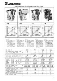
FUEL SYSTEM<br />
Fuel feeding / injection circuit<br />
Components: 1 Fuel Tank<br />
2 Fuel filter<br />
3 Fuel feeding tube<br />
4 Fuel lift pump<br />
5 lnjection pump<br />
6 Injector<br />
7 Fuel rail passage rubber joint<br />
8 Injector exhaust pipe<br />
9 Fuel tank cap<br />
10 Solenoid valve<br />
Note: The tank complete with filter is supplied on request.<br />
137<br />
Fuel filter detached from the tank (on request)<br />
1 Air relief valve<br />
2 Bearing<br />
3 Cartridge<br />
4 Rubber element<br />
5 Filtering element<br />
Cartridge characteristics:<br />
Filtering paper: ................................ PF 905<br />
Filtering surface:.............................. 2400 cm 2<br />
Degree of filtration:.......................... 2÷3 µ<br />
Maximum operating pressure: ........ 4 bar<br />
138<br />
See page 18 for periodic maintenance details.<br />
Fuel lift pump<br />
Components:<br />
1 Fuel lift pump<br />
2 Push rod<br />
3 Seal ring<br />
The fuel pump is membrane type. It is driven by camshaft cam via<br />
a drive rod.<br />
It is equipped with an external manual fuel lever.<br />
Characteristics:<br />
With the control cam at 1500 rpm the delivery rate is 75 l/hours and<br />
the self-adjusting pressure is at 0.55 to 0.65 bar.<br />
139<br />
Fuel pump drive rod projection - Assembly<br />
Rotate the timing shaft so that the eccentric is on the base radius<br />
and the drive rod is in place in its spherical seat in the control bush.<br />
The projection A of the drive rod 2 from the head level should be<br />
2÷2.5 mm.<br />
The check should be carried out with cam 1 at rest, as shown in the<br />
figure.<br />
Tighten the two fuel pump fastening nuts at 24 Nm.<br />
Check the length of the drive rod and if it is not the right size,<br />
replace it.<br />
Drive rod length = 153.15÷153.35 mm.<br />
140<br />
- 60 - FOCS Workshop Manual_cod. 1.5302.858_1° ed_ rev. 00