WORKSHOP MANUAL - lombardini service
WORKSHOP MANUAL - lombardini service
WORKSHOP MANUAL - lombardini service

Create successful ePaper yourself
Turn your PDF publications into a flip-book with our unique Google optimized e-Paper software.
<strong>WORKSHOP</strong> <strong>MANUAL</strong><br />
1003 FOCS Engine Series<br />
cod. 1-5302-858
1003 FOCS<br />
Engine Series<br />
PREFACE<br />
- Every attempt has been made to present within this <strong>service</strong> manual, accurate and up to date technical<br />
information.<br />
However, development on the LOMBARDINI series is continuous.<br />
Therefore, the information within this manual is subject to change without notice and without obligation.<br />
- The information contained within this <strong>service</strong> manual is the sole property of LOMBARDINI.<br />
As such, no reproduction or replication in whole or part is allowed without the express written permission of<br />
LOMBARDINI.<br />
Information presented within this manual assumes the following:<br />
1 - The person or people performing <strong>service</strong> work on LOMBARDINI series engines is properly trained and<br />
equipped to safely and professionally perform the subject operation;<br />
2 - The person or people performing <strong>service</strong> work on LOMBARDINI series engines possesses adequate hand and<br />
LOMBARDINI special tools to safely and professionally perform the subject <strong>service</strong> operation;<br />
3 - The person or people performing <strong>service</strong> work on LOMBARDINI series engines has read the pertinent<br />
information regarding the subject <strong>service</strong> operations and fully understands the operation at hand.<br />
- This manual was written by the manufacturer to provide technical and operating information to authorised<br />
LOMBARDINI after-sales <strong>service</strong> centres to carry out assembly, disassembly, overhauling, replacement and<br />
tuning operations.<br />
- As well as employing good operating techniques and observing the right timing for operations, operators must read<br />
the information very carefully and comply with it scrupulously.<br />
- Time spent reading this information will help to prevent health and safety risks and financial damage.<br />
Written information is accompanied by illustrations in order to facilitate your understanding of every step of the<br />
operating phases.<br />
FOCS Workshop Manual_cod. 1.5302.858_1° ed_ rev. 00<br />
- 3 -
-<br />
REGISTRATION OF MODIFICATIONS TO THE DOCUMENT<br />
Any modifications to this document must be registered by the drafting body, by completing the following table.<br />
Drafting<br />
body<br />
Document<br />
code<br />
Model<br />
N°<br />
Edition<br />
Revision<br />
Issue date<br />
Review<br />
date<br />
Endorsed<br />
CUSE/ATLO<br />
1-5302-858 51199<br />
1 0 31.10.2008 31.10.2008<br />
- 4 - FOCS Workshop Manual_cod. 1.5302.858_1° ed_ rev. 00
CHAPTER INDEX<br />
-<br />
This manual contains pertinent information regarding the repair of LOMBARDINI water-cooled, indirect injection Diesel<br />
engines type LDW 1003: updated October 31 st , 2008.<br />
CHAPTER INDEX<br />
1 GENERAL REMARKS AND SAFETY INFORMATION .................................................................. Pag. 9-11<br />
GENERAL SAFETY DURING OPERATING PHASES .................................................................................................... 11<br />
GENERAL SERVICE <strong>MANUAL</strong> NOTES ............................................................................................................................ 9<br />
GLOSSARY AND TERMINOLOGY ................................................................................................................................... 9<br />
SAFETY AND ENVIRONMENTAL IMPACT ....................................................................................................................11<br />
SAFETY AND WARNING DECALS ................................................................................................................................. 10<br />
SAFETY REGULATIONS ........................................................................................................................................... 10-11<br />
WARRANTY CERTIFICATE ............................................................................................................................................... 9<br />
2 TECHNICAL INFORMATION .................................................................................................................. 12-17<br />
MANUFACTURER AND ENGINE IDENTIFICATION ................................................................................................ 14-15<br />
PERFORMANCE DIAGRAMS .......................................................................................................................................... 16<br />
TECHINICAL SPECIFICATIONS ..................................................................................................................................... 17<br />
TROUBLE SHOOTING ............................................................................................................................................... 12-13<br />
3 MAINTENANCE - RECOMMENDED OIL TYPE - REFILLING .............................................................. 18-21<br />
ACEA Regualtions - ACEA Sequences ............................................................................................................................ 19<br />
API / MIL Sequence .......................................................................................................................................................... 19<br />
COOLANT ......................................................................................................................................................................... 21<br />
FUEL RECOMMENDATIONS .......................................................................................................................................... 21<br />
International specifications ............................................................................................................................................... 19<br />
LUBRICANT ...................................................................................................................................................................... 19<br />
PRESCRIBED LUBRICANT ............................................................................................................................................. 20<br />
ROUTINE ENGINE MAINTENANCE ............................................................................................................................... 18<br />
SAE Classification ........................................................................................................................................................... 19<br />
4 DISASSEMBLY / REASSEMBLY ........................................................................................................... 22-53<br />
Alternator/Cooling fan belt drive....................................................................................................................................... 25<br />
Big end bearing ................................................................................................................................................................. 46<br />
Camshaft ........................................................................................................................................................................... 36<br />
Camshaft journals and housings - Dimensions (mm) ..................................................................................................... 36<br />
Camshaft lobe measurement ........................................................................................................................................... 36<br />
Camshaft timing................................................................................................................................................................ 28<br />
Camshaft timing - Belt Reassembly ................................................................................................................................28<br />
Camshaft timing - Belt Tightening and Fastening ........................................................................................................... 29<br />
Camshaft timing - Belt tightening tool ............................................................................................................................. 29<br />
Camshaft timing pulley ..................................................................................................................................................... 28<br />
Camshaft timing pulley - Disassembly/Assembly ........................................................................................................... 28<br />
Camshaft timing pulley - Reference marks ..................................................................................................................... 28<br />
Camshaft, disassembly .................................................................................................................................................... 36<br />
Camshaft, journal and housing measurement ................................................................................................................ 36<br />
Central main bearing caps ............................................................................................................................................... 48<br />
Check the clearances between the bearings and the journal.......................................................................................... 48<br />
Clearances between the bearings and corresponding pins ............................................................................................51<br />
CONNECTING ROD ......................................................................................................................................................... 46<br />
Connecting rod alignment ................................................................................................................................................ 47<br />
Connecting rod with bearings and pin ............................................................................................................................. 46<br />
Connecting tod, weight ..................................................................................................................................................... 46<br />
Crankcase vacuum regulator valve .................................................................................................................................. 33<br />
Crankshaft axial clearance ............................................................................................................................................... 49<br />
Crankshaft front and back oil seal rings ..........................................................................................................................50<br />
Crankshaft timing pulley ................................................................................................................................................... 28<br />
Crankshaft, check journals and crank.............................................................................................................................. 50<br />
Crankshaft, lubrication lines ............................................................................................................................................. 50<br />
Cylinder head assembly ................................................................................................................................................... 45<br />
FOCS Workshop Manual_cod. 1.5302.858_1° ed_ rev. 00<br />
- 5 -
-<br />
Chapter index<br />
Cylinder head tightening procedure ................................................................................................................................. 45<br />
Cylinder head, removal..................................................................................................................................................... 37<br />
Cylinder roughness ........................................................................................................................................................... 47<br />
Cylinder, class ...................................................................................................................................................................47<br />
CYLINDERS ...................................................................................................................................................................... 47<br />
Driving pulley ....................................................................................................................................................................26<br />
E.G.R. Circuit ....................................................................................................................................................................23<br />
E.G.R. Circuit - Disassembly/Reassembly ...................................................................................................................... 24<br />
Exhaust manifold ..............................................................................................................................................................25<br />
Flywheel ............................................................................................................................................................................ 26<br />
Fuel rail ............................................................................................................................................................................. 34<br />
Governor springs ..............................................................................................................................................................31<br />
Head gasket ...................................................................................................................................................................... 44<br />
Injection pump control rod ................................................................................................................................................ 34<br />
Intake manifold – Remote air filter ................................................................................................................................... 23<br />
Intake, exhaust, injection camshaft lobe height ..............................................................................................................37<br />
Journal and connecting rod pins diameters ..................................................................................................................... 51<br />
Main bearings and connecting rod big ends diameters ..................................................................................................51<br />
Oil pan, removal ............................................................................................................................................................... 41<br />
Oil pump - Disassembly/Reassembly .............................................................................................................................. 32<br />
PISTON ............................................................................................................................................................................. 42<br />
Piston clearance ............................................................................................................................................................... 44<br />
Piston ring, Clearance between grooves (mm) ............................................................................................................... 43<br />
Piston ring, mounting order .............................................................................................................................................. 43<br />
Piston rings - End gaps (mm) .......................................................................................................................................... 43<br />
Piston supply ..................................................................................................................................................................... 42<br />
Piston, assembly ............................................................................................................................................................... 44<br />
Piston, class ...................................................................................................................................................................... 42<br />
Piston, disassembly and inspection ................................................................................................................................. 42<br />
Piston, weight ....................................................................................................................................................................43<br />
Pre-combustion chamber .................................................................................................................................................40<br />
Pre-combustion chamber ring nut removal ..................................................................................................................... 40<br />
Pre-combustion chamber, installation ............................................................................................................................. 41<br />
Pre-combustion chamber, removal .................................................................................................................................. 41<br />
Pump/injector unit - Disassembly .................................................................................................................................... 35<br />
Pump/injector unit - non-return valve............................................................................................................................... 34<br />
Rear and forward main bearing caps ............................................................................................................................... 48<br />
RECOMMENDATIONS FOR DISASSEMBLING AND ASSEMBLING ........................................................................... 22<br />
RECOMMENDATIONS FOR OVERHAULS AND TUNING ............................................................................................22<br />
Rocker arm assembly .......................................................................................................................................................35<br />
Rocker arm cover..............................................................................................................................................................32<br />
Rocker arm cover gasket ..................................................................................................................................................33<br />
Rocker arm pivot, dismounting and remounting ............................................................................................................. 35<br />
Shoulder half rings ............................................................................................................................................................ 49<br />
Shoulder half rings, oversized elements ..........................................................................................................................49<br />
Speed governor ................................................................................................................................................................. 30<br />
Speed governor - Limiting speed governor ...................................................................................................................... 31<br />
Speed governor - Reassembly ......................................................................................................................................... 31<br />
Speed governor components ...........................................................................................................................................30<br />
Stop pin rings, dismounting and remounting................................................................................................................... 42<br />
Tightening pulley ............................................................................................................................................................... 27<br />
Timing belt / Timing pulley arrangement ......................................................................................................................... 27<br />
Timing belt cover ..............................................................................................................................................................27<br />
Timing belt removal .......................................................................................................................................................... 27<br />
Vacuum pump and vacuum pump flange ........................................................................................................................ 25<br />
Valve / Rocker arm clearance .......................................................................................................................................... 33<br />
Valve guide insertion ........................................................................................................................................................39<br />
Valve guides and valve guide housings ........................................................................................................................... 39<br />
Valve recess and seat sealing width ................................................................................................................................40<br />
Valve seats and housings - .............................................................................................................................................. 40<br />
Valve springs..................................................................................................................................................................... 38<br />
Valve stem sealing rings - Reassembly ........................................................................................................................... 38<br />
Valve timing - Angles ........................................................................................................................................................30<br />
Valve timing check ............................................................................................................................................................ 29<br />
Valve, specifications ......................................................................................................................................................... 39<br />
Valves ................................................................................................................................................................................38<br />
- 6 - FOCS Workshop Manual_cod. 1.5302.858_1° ed_ rev. 00
Chapter index<br />
-<br />
5 LUBRIFICATION CIRCUIT ..................................................................................................................... 54-57<br />
Internal oil filter and oil sump return pipe ........................................................................................................................ 55<br />
Oil filter cartridge ..............................................................................................................................................................56<br />
Oil pressure check ............................................................................................................................................................ 56<br />
Oil pressure regulating valve ............................................................................................................................................56<br />
Oil pump ............................................................................................................................................................................ 55<br />
Oil pump, clearance between rotors ................................................................................................................................55<br />
6 COOLANT CIRCUIT ............................................................................................................................... 58-59<br />
COOLANT CIRCUIT ......................................................................................................................................................... 58<br />
Coolant circulation pump, components ........................................................................................................................... 59<br />
Radiator and compensation, check and seal tank cap. ..................................................................................................59<br />
Thermostatic valve............................................................................................................................................................ 59<br />
7 FUEL SYSTEM ....................................................................................................................................... 60-67<br />
Fuel feeding / injection circuit ........................................................................................................................................... 60<br />
Fuel filter detached from the tank (on request) ............................................................................................................... 60<br />
Fuel lift pump ....................................................................................................................................................................60<br />
Fuel pump drive rod projection - Assembly ..................................................................................................................... 60<br />
Injection advance ..............................................................................................................................................................65<br />
Injection advance control and regulation ......................................................................................................................... 65<br />
Injection pump assembly/disassembly ............................................................................................................................ 62<br />
Injection pumps delivery balancing .................................................................................................................................. 67<br />
Injector, nozzle projection ................................................................................................................................................. 64<br />
Injector, spark arrester...................................................................................................................................................... 64<br />
Instrument connection ...................................................................................................................................................... 66<br />
Plunger barrel ring nut assembly/disassembly ................................................................................................................ 62<br />
Plunger injection pump reassembly ................................................................................................................................. 62<br />
Preliminary steps to pump/injector unit delivery balancing test ..................................................................................... 66<br />
Pump/injector unit ............................................................................................................................................................. 61<br />
Pump/injector unit se.no. 6590.290 control data. ........................................................................................................... 63<br />
Pump/injector unit, components ......................................................................................................................................61<br />
Pumping element ..............................................................................................................................................................62<br />
Setting of injector ..............................................................................................................................................................64<br />
Static injection advance tuning ........................................................................................................................................ 66<br />
Test head B assembly ...................................................................................................................................................... 66<br />
8 ELECTRIC SYSTEM ............................................................................................................................... 68-73<br />
Alternator, 14V 33A ......................................................................................................................................................... 68<br />
Alternator, 14V 33A - Performance Curve ...................................................................................................................... 68<br />
Coolant high temperature lamp sensor............................................................................................................................ 72<br />
Electric starting layout (12V) with alternator 14V 33A ................................................................................................... 69<br />
Oil pressure switch ........................................................................................................................................................... 72<br />
Pre-heating glow plug ....................................................................................................................................................... 70<br />
Pre-heating plug control unit with coolant temperature sensor ......................................................................................71<br />
Pre-heating water temperature thermistor and Water temperature indicator thermal contact ......................................72<br />
STARTER MOTOR - Bosch DW 12V 1,1 KW ................................................................................................................ 70<br />
Starter motor, Bosch DW 12V 1,1 KW - Performance Curve........................................................................................ 70<br />
Temperature sensor for control unit ................................................................................................................................. 71<br />
Wiring diagram for pre-heating gear case ....................................................................................................................... 71<br />
9 SETTINGS ............................................................................................................................................... 74-77<br />
E.G.R. calibration ............................................................................................................................................................. 77<br />
Injection pump flow limiter and engine torque gearing device ........................................................................................ 75<br />
Pump injection delivery setting ........................................................................................................................................ 75<br />
Pump injection delivery standard setting without dynamometric brake ......................................................................... 75<br />
Pump/injector unit delivery setting with braked engine ................................................................................................... 76<br />
FOCS Workshop Manual_cod. 1.5302.858_1° ed_ rev. 00<br />
- 7 -
- Chapter index<br />
Pump/injector unit timing with speed governor ............................................................................................................... 74<br />
Required settings (as most commonly applies) ..............................................................................................................76<br />
Setting the idle maximum (standard) ............................................................................................................................... 74<br />
Setting the idle minimum (standard) ................................................................................................................................74<br />
Setting the stop ................................................................................................................................................................. 74<br />
SPEED SETTINGS ........................................................................................................................................................... 74<br />
10 STORAGE ............................................................................................................................................... 78-79<br />
ENGINE STORAGE .......................................................................................................................................................... 78<br />
PREPARING THE ENGINE FOR OPERATION AFTER PROTECTIVE TREATMENT ................................................. 79<br />
PROTECTIVE TREATMENT ............................................................................................................................................78<br />
11 TORQUE SPECIFICATIONS AND USE OF SEALANT ....................................................................... 80-81<br />
Table of tightening torques for standard screws (coarse thread) ................................................................................... 81<br />
Table of tightening torques for standard screws (fine thread) ........................................................................................ 81<br />
Table of tightening torques for the main components ..................................................................................................... 80<br />
12 SPECIAL TOOLS ......................................................................................................................................... 82<br />
- 8 - FOCS Workshop Manual_cod. 1.5302.858_1° ed_ rev. 00
GENERAL REMARKS AND SAFETY INFORMATION<br />
1<br />
WARRANTY CERTIFICATE<br />
- The products manufactured by LOMBARDINI S.r.l. are warranted to be free from conformity defects for a period of 24 months<br />
from the date of delivery to the first end user.<br />
- For engines fitted to stationary equipment, working at constant load and at constant and/or slightly variable speed within the<br />
setting limits, the warranty covers a period up to a limit of 2000 working hours, if the above mentioned period (24 months) is<br />
not expired.<br />
- If no hour-meter is fitted , 12 working hours per calendar day will be considered.<br />
- For what concerns the parts subject to wear and deterioration (injection/feeding system, electrical system, cooling system,<br />
sealing parts, non-metallic pipes, belts) warranty covers a maximum limit of 2000 working hours, if the above mentioned period<br />
(24 months) is not expired.<br />
- For correct maintenance and replacement of these parts, it is necessary to follow the instructions reported in the documentation<br />
supplied with each engine.<br />
- To ensure the engine warranty is valid, the engine installation, considering the product technical features, must be carried out<br />
by qualified personnel only.<br />
- The list of the LOMBARDINI S.r.l. authorized dealers is reported in the “Service” booklet, supplied with each engine.<br />
- Special applications involving considerable modifications to the cooling/lubricating system (for ex.: dry oil sump), filtering<br />
system, turbo-charged models, will require special written warranty agreements.<br />
- Within the above stated periods LOMBARDINI S.r.l. directly or through its authorized network will repair and/or replace free<br />
of charge any own part or component that, upon examination by LOMBARDINI S.r.l. or by an authorized LOMBARDINI S.r.l.<br />
agent, is found to be defective in conformity, workmanship or materials.<br />
- Any other responsibility/obligation for different expenses, damages and direct/indirect losses deriving from the engine use or<br />
from both the total or partial impossibility of use, is excluded.<br />
- The repair or replacement of any component will not extend or renew the warranty period.<br />
LOMBARDINI S.r.l. warranty obligations here above described will be cancelled if:<br />
- LOMBARDINI S.r.l. engines are not correctly installed and as a consequence the correct functional parameters are not<br />
respected and altered.<br />
- LOMBARDINI S.r.l. engines are not used according to the instructions reported in the “Use and Maintenance” booklet<br />
supplied with each engine.<br />
- Any seal affixed to the engine by LOMBARDINI S.r.l. has been tampered with or removed.<br />
- Spare parts used are not original LOMBARDINI S.r.l..<br />
- Feeding and injection systems are damaged by unauthorized or poor quality fuel types.<br />
- Electrical system failure is due to components, connected to this system, which are not supplied or installed by<br />
LOMBARDINI S.r.l..<br />
- Engines have been disassembled, repaired or altered by any part other than an authorized LOMBARDINI agent.<br />
- Following expiration of the above stated warranty periods and working hours, LOMBARDINI S.r.l. will have no further<br />
responsibility for warranty and will consider its here above mentioned obligations for warranty complete.<br />
- Any warranty request related to a non-conformity of the product must be addressed to the LOMBARDINI S.r.l. <strong>service</strong> agents.<br />
GENERAL SERVICE <strong>MANUAL</strong> NOTES<br />
1 - Use only genuine LOMBARDINI S.r.l. repair parts.<br />
Failure to use genuine LOMBARDINI S.r.l. parts could result in sub-standard performance and low longevity.<br />
2 - All data presented are in metric format. That is, dimensions are presented in millimeters (mm), torque is presented in<br />
Newton-meters (Nm), weight is presented in kilograms (Kg), volume is presented in liters or cubic centimeters (cc) and<br />
pressure is presented in barometric units (bar).<br />
GLOSSARY AND TERMINOLOGY<br />
For clarity, here are the definitions of a number of terms used recurrently in the manual.<br />
- Cylinder number one: is the flywheel side piston .<br />
- Rotation direction: anticlockwise «viewed from the flywheel side of the engine».<br />
FOCS Workshop Manual_cod. 1.5302.858_1° ed_ rev. 00<br />
- 9 -
1<br />
General remarks and safety information<br />
SAFETY AND WARNING DECALS<br />
- Important remarks and features of the text are highlighted<br />
using symbols, which are explained below:<br />
Danger – Attention<br />
This indicates situations of grave danger which, if ignored,<br />
may seriously threaten the health and safety of individuals.<br />
Caution – Warning<br />
This indicates that it is necessary to take proper precautions<br />
to prevent any risk to the health and safety of individuals<br />
and avoid financial damage.<br />
Important<br />
This indicates particularly important technical information<br />
that should not be ignored.<br />
SAFETY REGULATIONS<br />
− LOMBARDINI Engines are built to supply their performances in a safe and long-lasting way.<br />
To obtain these results, it is essential for users to comply with the servicing instructions given in the relative manual along with<br />
the safety recommendations listed below.<br />
− The engine has been made according to a machine manufacturer's specifications and all actions required to meet the essential<br />
safety and health safeguarding requisites have been taken, as prescribed by the current laws in merit.<br />
All uses of the engine beyond those specifically established cannot therefore be considered as conforming to the use defined<br />
by LOMBARDINI which thus declines all liability for any accidents deriving from such operations.<br />
− The following indications are dedicated to the user of the machine in order to reduce or eliminate risks concerning engine<br />
operation in particular, along with the relative routine maintenance work.<br />
− The user must read these instructions carefully and become familiar with the operations described.<br />
Failure to do this could lead to serious danger for his personal safety and health and that of any persons who may be in the<br />
vicinity of the machine.<br />
• The engine may only be used or assembled on a machine by technicians who are adequately trained about its operation and<br />
the deriving dangers.<br />
This condition is also essential when it comes to routine and, above all, extraordinary maintenance operations which, in the<br />
latter case, must only be carried out by persons specifically trained by LOMBARDINI and who work in compliance with the<br />
existing documentation.<br />
− Variations to the functional parameters of the engine, adjustments to the fuel flow rate and rotation speed, removal of seals,<br />
demounting and refitting of parts not described in the operation and maintenance manual by unauthorized personnel shall<br />
relieve LOMBARDINI from all and every liability for deriving accidents or for failure to comply with the laws in merit.<br />
− On starting, make sure that the engine is as horizontal as possible, unless the machine specifications differ.<br />
In the case of manual start-ups, make sure that the relative actions can take place without the risk of hitting walls or dangerous<br />
objects, also considering the movements made by the operator.<br />
Pull-starting with a free cord (thus excluding self-winding starting only), is not permitted even in an emergency.<br />
− Make sure that the machine is stable to prevent the risk of overturning.<br />
− Become familiar with how to adjust the rotation speed and stop the engine.<br />
− Never start the engine in a closed place or where there is insufficient ventilation.<br />
Combustion creates carbon monoxide, an odourless and highly poisonous gas.<br />
Lengthy stays in places where the engine freely exhausts this gas can lead to unconsciousness and death.<br />
− The engine must not operate in places containing inflammable materials, in explosive atmospheres, where there is dust that<br />
can easily catch fire unles specific, adequate and clearly indicated precautions have been taken and have been certified for<br />
the machine.<br />
− To prevent fire hazards, always keep the machine at least one meter from buildings or from other machinery.<br />
− Children and animals must be kept at a due distance from operating machines in order to prevent hazards deriving from<br />
their operation.<br />
− Fuel is inflammable.<br />
The tank must only be filled when the engine is off.<br />
Thoroughly dry any spilt fuel and move the fuel container away along with any rags soaked in fuel or oil.<br />
Make sure that no soundproofing panels made of porous material are soaked in fuel or oil.<br />
Make sure that the ground or floor on which the machine is standing has not soaked up any fuel or oil.<br />
− Fully tighten the tank plug each time after refuelling.<br />
Do not fill the tank right to the top but leave an adequate space for the fuel to expand.<br />
− Fuel vapour is highly toxic.<br />
Only refuel outdoors or in a well ventilated place.<br />
− Do not smoke or use naked flames when refuelling.<br />
− The engine must be started in compliance with the specific instructions in the operation manual of the engine and/or<br />
machine itself.<br />
Do not use auxiliary starting aids that were not installed on the original machine (e.g. Startpilot’).<br />
− Before starting, remove any tools that were used to <strong>service</strong> the engine and/or machine.<br />
Make sure that all guards have been refitted.<br />
- 10 - FOCS Workshop Manual_cod. 1.5302.858_1° ed_ rev. 00
General remarks and safety information<br />
1<br />
− During operation, the surface of the engine can become dangerously hot.<br />
Avoid touching the exhaust system in particular.<br />
− Before proceeding with any operation on the engine, stop it and allow it to cool.<br />
Never carry out any operation whilst the engine is running.<br />
− The coolant fluid circuit is under pressure.<br />
Never carry out any inspections until the engine has cooled and even in this case, only open the radiator plug or<br />
expansion chamber with the utmost caution, wearing protective garments and goggles. If there is an electric fan, do not<br />
approach the engine whilst it is still hot as the fan could also start operating when the engine is at a standstill.<br />
Only clean the coolant system when the engine is at a standstill.<br />
− When cleaning the oil-cooled air filter, make sure that the old oil is disposed of in the correct way in order to safeguard<br />
the environment.<br />
The spongy filtering material in oil-cooled air filters must not be soaked in oil.<br />
The reservoir of the separator pre-filter must not be filled with oil.<br />
− The oil must be drained whilst the engine is hot (oil T ~ 80°C).<br />
Particular care is required to prevent burns.<br />
Do not allow the oil to come into contact with the skin.<br />
− Pay attention to the temperature of the oil filter when the filter itself is replaced.<br />
− Only check, top up and change the coolant fluid when the engine is off and cold.<br />
Take care to prevent fluids containing nitrites from being mixed with others that do not contain these substances since<br />
"Nitrosamine", dangerous for the health, can form.<br />
The coolant fluid is polluting and must therefore be disposed of in the correct way to safeguard the environment.<br />
− During operations that involve access to moving parts of the engine and/or removal of rotating guards, disconnect and<br />
insulate the positive wire of the battery to prevent accidental short-circuits and to stop the starter motor from being<br />
energized.<br />
− Only check belt tension when the engine is off.<br />
− Only use the eyebolts installed by LOMBARDINI to move the engine.<br />
These lifting points are not suitable for the entire machine; in this case, the eyebolts installed by the manufacturer should<br />
be used.<br />
GENERAL SAFETY DURING OPERATING PHASES<br />
– The procedures contained in this manual have been tested and selected by the manufacturer’s technical experts, and hence<br />
are to be recognised as authorised operating methods.<br />
– A number of procedures must be carried out with the aid of equipment and tools that simplify and improve the timing of<br />
operations.<br />
– All tools must be in good working condition so that engine components are not damaged and that operations are carried out<br />
properly and safely.<br />
It is important to wear the personal safety devices prescribed by work safety laws and also by the standards of this manual.<br />
– Holes must be lined up methodically and with the aid of suitable equipment. Do not use your fingers to carry out this operation<br />
to avoid the risk of amputation.<br />
– Some phases may require the assistance of more than one operator. If so, it is important to inform and train them regarding<br />
the type of activity they will be performing in order to prevent risks to the health and safety of all persons involved.<br />
– Do not use flammable liquids (petrol, diesel, etc.) to degrease or wash components. Use special products.<br />
– Use the oils and greases recommended by the manufacturer.<br />
Do not mix different brands or combine oils with different characteristics.<br />
– Discontinue use of the engine if any irregularities arise, particularly in the case of unusual vibrations.<br />
– Do not tamper with any devices to alter the level of performance guaranteed by the manufacturer.<br />
SAFETY AND ENVIRONMENTAL IMPACT<br />
Every organisation has a duty to implement procedures to<br />
identify, assess and monitor the influence of its own activities<br />
(products, <strong>service</strong>s, etc.) on the environment.<br />
Procedures for identifying the extent of the impact on the<br />
environment must consider the following factors:<br />
- Liquid waste<br />
- Waste management<br />
- Soil contamination<br />
- Atmospheric emissions<br />
- Use of raw materials and natural resources<br />
- Regulations and directives regarding environmental impact<br />
In order to minimise the impact on the environment, the<br />
manufacturer now provides a number of indications to be<br />
followed by all persons handling the engine, for any reason,<br />
during its expected lifetime.<br />
- All packaging components must be disposed of in accordance<br />
with the laws of the country in which disposal is taking place.<br />
- Keep the fuel and engine control systems and the exhaust<br />
pipes in efficient working order to limit environmental and<br />
noise pollution.<br />
- When discontinuing use of the engine, select all components<br />
according to their chemical characteristics and dispose of<br />
them separately.<br />
FOCS Workshop Manual_cod. 1.5302.858_1° ed_ rev. 00<br />
- 11 -
2<br />
TECHNICAL INFORMATION<br />
TROUBLE SHOOTING<br />
THE ENGINE MUST BE STOPPED IMMEDIATELY WHEN:<br />
1) - The engine rpms suddenly increase and decrease;<br />
2) - A sudden and unusual noise is heard;<br />
3) - The colour of the exhaust fumes suddenly darkens;<br />
4) - The oil pressure indicator light turns on while running.<br />
TABLE OF LIKELY ANOMALIES AND THEIR SYMPTOMS<br />
The following table contains the possible causes of some failures which may occur during operation.<br />
Always perform these simple checks before removing or replacing any part.<br />
TROUBLE<br />
POSSIBLE CAUSE<br />
Engine does not start<br />
Engine starts but stops<br />
No acceleration<br />
Non-uniform speed<br />
Black smoke<br />
White smoke<br />
Oil preassure too low<br />
Oil level increase<br />
Excessive oil<br />
consumption<br />
Oil and fuel dripping<br />
from the exhaust<br />
Engine overheats<br />
Inadequate<br />
performance<br />
High noise level<br />
Clogged fuel pipes<br />
Clogged fuel filter<br />
Air or water in the fuel circuit<br />
FUEL<br />
CIRCUIT<br />
Tank cap breather blocked<br />
Faulty fuel pump<br />
Lack of fuel<br />
Glow plug fuse burned<br />
Faulty glow plug control relay<br />
ELECTRIC<br />
SYSTEM<br />
MAINTENANCE<br />
SETTINGS REPAIRS<br />
Flat battery<br />
Unclear or mistaken cable connection<br />
Faulty starter switch<br />
Faulty starting motor<br />
Faulty glow plugs<br />
Clogged air filter<br />
Prolonged operation at idle<br />
Incomplete run-in<br />
Overloaded engine<br />
Excessive valve clearances<br />
Absence of valve clearances<br />
Incorrect speed governor leverages<br />
Speed governor spring broken or disengaged<br />
Idle low<br />
Worn out or stuck rings<br />
Worn out cylinders<br />
Worn out valve guides<br />
Bad valve seal<br />
Bearing shells of bearing cap - piston rod -<br />
rocker worn out<br />
E.G.R. valve blocked open<br />
Governor leverages not running<br />
Cylinder head gasket damaged<br />
Faulty timing system<br />
Supplementary starter spring broken or<br />
disengaged<br />
- 12 - FOCS Workshop Manual_cod. 1.5302.858_1° ed_ rev. 00
Technical information<br />
2<br />
TROUBLE<br />
POSSIBLE CAUSE<br />
Engine does not start<br />
Engine starts but stops<br />
No acceleration<br />
Non-uniform speed<br />
Black smoke<br />
White smoke<br />
Oil preassure too low<br />
Oil level increase<br />
Excessive oil<br />
consumption<br />
Oil and fuel dripping<br />
from the exhaust<br />
Engine overheats<br />
Inadequate<br />
performance<br />
High noise level<br />
LUBRICATION<br />
CIRCUIT<br />
High oil level<br />
Low oil level<br />
Dirty or blocked pressure regulation valve<br />
Worn oil pump<br />
Air to the oil suction hose<br />
Faulty manometer or pressure switch<br />
Oil in sump suction hose blocked<br />
Oil in sump drainage pipe blocked<br />
Faulty spray nozzles (Turbo engines only)<br />
INJECTION<br />
Damaged injector<br />
Damaged injection pump valve<br />
Incorrectly calibrated injector<br />
Worn or damaged pumping element<br />
Incorrect injection pump delivery setting<br />
(delivery equalisation)<br />
Hardened pump/injector control rod<br />
Cracked or broken pre-combustion<br />
chamber<br />
Incorrect adjustment of the injection<br />
systems (delivery equalisation advance)<br />
Insufficient refrigerant fluid<br />
Defective fan, radiator, or radiator cap<br />
Defective thermostatic valve<br />
COOLING<br />
CIRCUIT<br />
Loss of refrigerant fluid from the radiator,<br />
hoses, engine crankshaft or water pump.<br />
Inside of radiator or coolant lines obstructed.<br />
Defective or worn water pump<br />
Alternator fan drive belt loose or torn<br />
Heat exchange surface of the radiator clogged<br />
FOCS Workshop Manual_cod. 1.5302.858_1° ed_ rev. 00<br />
- 13 -
2 Technical information<br />
MANUFACTURER AND ENGINE IDENTIFICATION<br />
Manufacturer identification<br />
Engine type<br />
Engine serial number<br />
Maximum operating speed<br />
Number of the customer version<br />
(form K)<br />
Approval data<br />
- 14 - FOCS Workshop Manual_cod. 1.5302.858_1° ed_ rev. 00
Technical information<br />
2<br />
ENGINE TYPE<br />
Cylinders<br />
Bore<br />
Stroke<br />
Displacements<br />
Compression rate<br />
Rpm<br />
Maximum power N 80/1269/CEE-ISO 1585-DIN 70020<br />
Maximum torque<br />
Specific fuel consumption**<br />
Oil consumption **<br />
Dry weight of engine<br />
Combustion air volume at 3600 Rpm<br />
Cooling air volume at 3600 Rpm<br />
Axial load allowed on crankshaft (both directions)<br />
Max tilt<br />
Instant operation (up to 1 min)<br />
Intermittent operation (up to 30 min)<br />
N°<br />
mm<br />
mm<br />
Cm³<br />
Nm<br />
RPM<br />
g/KWh<br />
Kg/h<br />
Kg<br />
l./1'<br />
m³/min<br />
Kg.<br />
α<br />
α<br />
LDW<br />
1003<br />
3<br />
75<br />
77.6<br />
1028<br />
22,8:1<br />
3600<br />
19<br />
58<br />
@ 2200<br />
300<br />
0,013<br />
87<br />
1850<br />
63<br />
300<br />
35°<br />
25°<br />
** At max. power<br />
FOCS Workshop Manual_cod. 1.5302.858_1° ed_ rev. 00<br />
- 15 -
2<br />
Technical information<br />
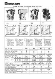
PERFORMANCE DIAGRAMS<br />
LDW 1003<br />
70<br />
60<br />
256<br />
250<br />
256<br />
260<br />
50<br />
250<br />
287<br />
294<br />
304<br />
244<br />
245<br />
250<br />
255<br />
40<br />
Nm<br />
260<br />
270<br />
30<br />
290<br />
20<br />
320<br />
400<br />
10<br />
600<br />
0<br />
1200 1300 1400 1500 1600 1700 1800 1900 2000 2100 2200 2300 2400 2500 2600 2700 2800 2900 3000 3100 3200 3300 3400 3500 3600 3700<br />
rpm<br />
N (80/1269/CEE - ISO 1585 - DIN 70020)<br />
AUTOMOTIVE RATING: intermittent operation with variable speed and variable load.<br />
The above power values refer to an engine fitted with air cleaner and standard muffler, after testing and at the<br />
environmental conditions of 20°C and 1 bar. Max. power tolerance is 5%. Power decreases by approximately 1% every<br />
100 m di altitude and by 2% every 5°C above 25°C.<br />
Note: Consult LOMBARDINI for power, torque curves and specific consumptions at rates differing from those given above.<br />
Important<br />
Non-approval by Lombardini for any modifications releases the company from any damages incurred by the<br />
engine.<br />
- 16 - FOCS Workshop Manual_cod. 1.5302.858_1° ed_ rev. 00
Technical information<br />
2<br />
TECHNICAL SPECIFICATIONS<br />
A<br />
B<br />
M<br />
N<br />
O<br />
D<br />
C<br />
L<br />
K<br />
J<br />
P<br />
R<br />
S<br />
Q<br />
F<br />
G<br />
I<br />
H<br />
E<br />
V<br />
T<br />
U<br />
X<br />
W<br />
YZ<br />
A1<br />
A<br />
B<br />
C<br />
D<br />
239,1<br />
181,2<br />
351,7<br />
268,1<br />
J<br />
K<br />
L<br />
M<br />
DIMENSIONS (mm)<br />
58<br />
12<br />
157,4<br />
135<br />
S<br />
T<br />
U<br />
V<br />
30<br />
266<br />
383<br />
63,5<br />
E<br />
216<br />
N<br />
397,7<br />
W<br />
155,8<br />
F<br />
176,3<br />
O<br />
334,5<br />
X<br />
145,2<br />
G<br />
88<br />
P<br />
141,9<br />
Y<br />
25<br />
H<br />
86<br />
Q<br />
148,7<br />
Z<br />
13<br />
I<br />
30<br />
R<br />
16<br />
A1<br />
306,1<br />
FOCS Workshop Manual_cod. 1.5302.858_1° ed_ rev. 00<br />
- 17 -
3<br />
MAINTENANCE - RECOMMENDED OIL TYPE - REFILLING<br />
ROUTINE ENGINE MAINTENANCE<br />
Important<br />
Non compliance with the instructions provided in the chart entails risk of technical damages to the machine and/or<br />
the system. Carry out maintenance regularly (after predefined number of km, or within the time intervals scheduled).<br />
Continue the periodical maintenance after 100,000 km by starting from 7,500 km.<br />
ORDINARY MAINTENANCE<br />
( x 1000 Km )<br />
1<br />
FREQUENCY x KM<br />
10 20 30 40 50 60 70 80 90 100 110 120 130 140 150<br />
(6) 1 1,5 2 2,5 3 3,5 4 4,5 5 5,5 6 6,5 7 7,5<br />
OPERATION<br />
CLEANING<br />
CHECK<br />
REPLACEMENT<br />
COMPONENT<br />
Radiator fins<br />
Valve and rocker<br />
arms clearance<br />
Engine oil<br />
Solenoid valve<br />
operation<br />
Fuel pipes and<br />
connections<br />
Coolant<br />
Alternator belt<br />
Timing belt<br />
Air filter element<br />
Engine oil<br />
Oil filter<br />
Fuel filter<br />
Coolant<br />
Alternator belt<br />
Timing belt<br />
Fuel pipe<br />
EVERY 10.000 Km<br />
EVERY 3.500 Km<br />
EVERY 3.500 Km<br />
EVERY 50.000 Km<br />
EVERY 10.000 Km<br />
EVERY 10.000 Km<br />
EVERY 10.000 Km<br />
EVERY 100.000 km (or when disassembling)<br />
EVERY 4 years<br />
- 18 - FOCS Workshop Manual_cod. 1.5302.858_1° ed_ rev. 00
Maintenance - Recommended oil type - Refilling<br />
3<br />
LUBRICANT<br />
SAE Classification<br />
In the SAE classification, oils differ on the basis of their<br />
viscosity, and no other qualitative characteristic is taken<br />
into account.<br />
The first number refers to the viscosity when the engine is<br />
cold (symbol W = winter), while the second considers<br />
viscosity with the engine at régime.<br />
The criteria for choosing must consider, during winter, the<br />
lowest outside temperature to which the engine will be<br />
subject and the highest functioning temperature during<br />
summer.<br />
Single-degree oils are normally used when the running<br />
temperature varies scarcely.<br />
Multi-degree oil is less sensitive to temperature<br />
changes.<br />
-<br />
40<br />
-<br />
35<br />
-<br />
30<br />
- - - - -<br />
25 20 15 10 5 0<br />
SAE 10W*<br />
123456789012<br />
123456789012<br />
+<br />
5<br />
SAE 20W*<br />
+<br />
10<br />
1234567890<br />
123456789012<br />
1234567890<br />
SAE 30*<br />
1234567890123456789<br />
1234567890123456789<br />
SAE 40*<br />
1234567890123456789<br />
1234567890123456789<br />
1234567890123456<br />
123456789012345678901234<br />
1234567890123456<br />
123456789012345678901234<br />
SAE 10W-30**<br />
123456789012345678901234<br />
SAE 10W-40**<br />
12345678901234567890123456789<br />
12345678901234567890123456789<br />
SAE 10W-60**<br />
123456789012345678901234567890121<br />
123456789012345678901234567890121<br />
SAE 15W-40 **<br />
123456789012345678901234567890121<br />
1234567890123456789012345<br />
SAE 15W-40 **<br />
1234567890123456789012345<br />
123456789012345678901234567<br />
123456789012345678901234567<br />
12345678901234567890123456789<br />
SAE 20W-60 **<br />
12345678901234567890123456789<br />
12345678901234567890123456789<br />
SAE 5W-30 ***<br />
SAE 0W-30 ***<br />
+<br />
15<br />
SAE 5W-40 ***<br />
+<br />
20<br />
+<br />
25<br />
+<br />
30<br />
+<br />
35<br />
+<br />
40<br />
+<br />
45<br />
+<br />
50<br />
SAE- Grade<br />
* Mineral base<br />
** Semi-synthetic base<br />
*** Synthetic base<br />
International specifications<br />
They define testing performances and procedures that the lubricants need to successfully respond to in several engine testing<br />
and laboratory analysis so as to be considered qualified and in conformity to the regulations set for each lubrication kind.<br />
A.P.I : ( American Petroleum Institute )<br />
MIL : Engine oil U.S. military specifications released for logistic reasons<br />
ACEA : European Automobile Manufacturers Association<br />
Tables shown on this page are of useful reference when buying a kind of oil.<br />
Codes are usually printed-out on the oil container and the understanding of their meaning is useful for comparing different brands<br />
and choosing the kind with the right characteristics.<br />
Usually a specification showing a following letter or number is preferable to one with a preceding letter or number.<br />
An SF oil, for instance, is more performing than a SE oil but less performing than a SG one.<br />
ACEA Regualtions - ACEA Sequences<br />
LIGHT DUTY DIESEL ENGINES<br />
B1 =Low-viscosity, for frictions reduction<br />
B2 =Standard<br />
B3 =High performances (indirect injection)<br />
B4 =High quality (direct injection)<br />
HEAVY DUTY DIESEL ENGINES<br />
E1 =OBSOLETE<br />
12345678901<br />
12345678901<br />
12345678901<br />
E2 =Standard<br />
E3 =Heavy conditions (Euro 1 - Euro 2 engines )<br />
E4 =Heavy conditions (Euro 1 - Euro 2 - Euro 3 engines )<br />
E5 =High performances in heavy conditions (Euro 1 - Euro 2 -<br />
Euro 3 engines )<br />
API / MIL Sequences<br />
DIESEL<br />
PETROL<br />
123456789012345<br />
12345678901<br />
1234567890123456789012345<br />
API CH-4 CG-4 CF-4 CF-2 CF CE CD CC SC SD SE SF SG SH SJ SL<br />
1234567890123456789012345<br />
1234567890123456789012345<br />
MIL<br />
L- 46152 D / E<br />
CURRENT<br />
123456789012345678<br />
123456789012345678<br />
OBSOLETE<br />
123456789012345678<br />
FOCS Workshop Manual_cod. 1.5302.858_1° ed_ rev. 00<br />
- 19 -
3<br />
Maintenance - Recommended oil type - Refilling<br />
PRESCRIBED LUBRICANT<br />
AGIP SINT 2000<br />
5 W 40<br />
specifications<br />
API SJ / CF 4<br />
ACEA A3-96 B3-96<br />
MIL - L-46152 D/E<br />
In the countries where AGIP products are not available, use oil API CF/SH for Diesel engines or oil corresponding to the<br />
military specification MIL-L-2104 C/46152 D.<br />
OIL CAPACITY<br />
LDW 1003<br />
OIL VOLUME<br />
(OIL FILTER INCLUDED)<br />
Litres<br />
max<br />
min<br />
4,1<br />
3,1<br />
OIL VOLUME<br />
(WITHOUT OIL FILTER)<br />
Litres<br />
max<br />
min<br />
4,0<br />
3,0<br />
Danger – Attention<br />
- The engine may be damaged if operated with insufficient lube oil. It is also dangerous to supply too much lube oil<br />
to the engine because a sudden increase in engine rpm could be caused by its combustion.<br />
- Use proper lube oil preserve your engine. Good quality or poor quality of the lubricating oil has an affect on engine<br />
performance and life.<br />
- If inferior oil is used, or if your engine oil is not changed regularly, the risk of piston seizure, piston ring sticking,<br />
and accelerated wear of the cylinder liner, bearing and other moving components increases significantly.<br />
- Always use oil with the right viscosity for the ambient temperature in which your engine is being operated.<br />
Danger – Attention<br />
- The used engine oil can cause skin-cancer if kept frequently in contact for prolonged periods.<br />
- If contact with oil cannot be avoided, wash carefully your hands with water and soap as soon as possible.<br />
- Do not disperse the oil in the ambient, as it has a high pollution power.<br />
- 20 - FOCS Workshop Manual_cod. 1.5302.858_1° ed_ rev. 00
Maintenance - Recommended oil type - Refilling<br />
3<br />
COOLANT<br />
Danger – Attention<br />
- The fluid coolant circuit is pressurized. Inspections must only be made when the engine has cooled and even in<br />
this case, the radiator or expansion chamber plug must be unscrewed with the utmost caution.<br />
- If an electric fan is installed, do not approach a hot engine since the fan itself could start up even when the<br />
engine is at a standstill.<br />
- Coolant fluid is polluting, it must therefore be disposed of in the correct way. Do not litter.<br />
The anti-freeze protection liquid (AGIP ANTIFREEZE SPEZIAL) must be used mixed with water, preferably decalcified. The<br />
freezing point of the cooling mixture depends on the product concentration in water, it is therefore recommended to use a 50%<br />
diluted mixture which guarantees a certain degree of optimal protection. As well as lowering the freezing point, the permanent<br />
liquid also raises the boiling point.<br />
Coolant refueling<br />
ENGINE TYPE<br />
CAPACITY (Litres) Without radiator<br />
LDW 1003<br />
1,30<br />
For information concerning the capacity of Lombardini radiators, please contact Lombardini directly.<br />
The total volume for refilling the cooling liquid varies according to the type of engine and radiator.<br />
FUEL RECOMMENDATIONS<br />
Purchase diesel fuel in small quantities and store in clean, approved containers. Clean fuel prevents the diesel fuel injectors<br />
and pumps from clogging. Do not overfill the fuel tank.<br />
Leave room for the fuel to expand. Immediately clean up any spillage during refueling.<br />
Never store diesel fuel in galvanized containers; diesel fuel and the galvanized coating react chemically to each other, producing<br />
flaking that quickly clogs filters or causes fuel pump or injector failure.<br />
High sulfur content in fuel may cause engine wear. In those countries where diesel has a high sufur content, its is advisable to<br />
lubricate the engine with a high alkaline oil or alternatively to replace the lubricating oil recommended by the manufacturer<br />
more frequently. The regions in which diesel normally has a low sulfur content are Europe, North America, and Australia.<br />
PRESCRIBED LUBRICANT<br />
Fuel with low sulphur content<br />
Fuel with high sulphur content<br />
API CF4 - CG4<br />
API CF<br />
FUEL TYPE<br />
For best results, use only clean, fresh, commercial-grade diesel fuel. Diesel fuels that satisfy the following specifications are<br />
suitable for use in this engine: ASTM D-975 - 1D or 2D, EN590, or equivalent.<br />
FUELS FOR LOW TEMPERATURES<br />
It is possible to run the engine at temperatures below 0°C using special winter fuels. These fuels reduce the formation of paraffin<br />
in diesel at low temperatures. If paraffin forms in the diesel, the fuel filter becomes blocked interrupting the flow of fuel.<br />
Fuel can be: - Summer up to 0°C<br />
- Winter up to -10°C<br />
- Alpine up to -20°C<br />
- Arctic up to -30°C<br />
BIODIESEL FUEL<br />
Fuels containing less than 20% methyl ester or B20, are suitable for use in this<br />
engine. Biodiesel fuels meeting the specification of BQ-9000 or equivalent are<br />
recommended. DO NOT use vegetable oil as a biofuel for this engine.<br />
Any failures resulting from the use of fuels other than recommended will not be<br />
warranted.<br />
AVIATION FUEL<br />
Aviation fuels suitable for use in this engine include JP5, JP4, JP8 and, JET-A<br />
(if 5 percent oil is added).<br />
FOCS Workshop Manual_cod. 1.5302.858_1° ed_ rev. 00<br />
EMISSION CONTROL INFORMATION<br />
LOW SULFUR FUEL OR<br />
ULTRA LOW SULFUR FUEL ONLY<br />
EPA /CARB emission label must be<br />
attached near the fuel inlet.<br />
- 21 -
4<br />
DISASSEMBLY / REASSEMBLY<br />
RECOMMENDATIONS FOR DISASSEMBLING AND ASSEMBLING<br />
Important<br />
To locate specific topics, the reader should refer to the index.<br />
– Besides disassembly and reassembly operations this chapter also includes checking and setting specifications, dimensions,<br />
repair and operating instructions.<br />
– Always use original LOMBARDINI spare parts for proper repair operations.<br />
– The operator must wash, clean and dry components and assemblies before installing them.<br />
– The operator must make sure that the contact surfaces are intact, lubricate the coupling parts and protect those that are<br />
prone to oxidation.<br />
– Before any intervention, the operator should lay out all equipment and tools in such a way as to enable him to carry out<br />
operations correctly and safely.<br />
– For safety and convenience, you are advised to place the engine on a special rotating stand for engine overhauls.<br />
– Before proceeding with operations, make sure that appropriate safety conditions are in place, in order to safeguard the<br />
operator and any persons involved.<br />
– In order to fix assemblies and/or components securely, the operator must tighten the fastening parts in a criss-cross or<br />
alternating pattern.<br />
– Assemblies and/or components with a specific tightening torque must initially be fastened at a level lower than the assigned<br />
value, and then subsequently tightened to the final torque.<br />
RECOMMENDATIONS FOR OVERHAULS AND TUNING<br />
Important<br />
To locate specific topics, the reader should refer to the index.<br />
– Before any intervention, the operator should lay out all equipment and tools in such a way as to enable him to carry out<br />
operations correctly and safely.<br />
– The operator must comply with the specific measures described in order to avoid errors that might cause damage to the<br />
engine.<br />
– Before carrying out any operation, clean the assemblies and/or components thoroughly and eliminate any deposits or<br />
residual material.<br />
– Wash the components with special detergent and do not use steam or hot water.<br />
– Do not use flammable products (petrol, diesel, etc.) to degrease or wash components. Use special products.<br />
– Dry all washed surfaces and components thoroughly with a jet of air or special cloths before reassembling them.<br />
– Apply a layer of lubricant over all surfaces to protect them against oxidation.<br />
– Check all components for intactness, wear and tear, seizure, cracks and/or faults to be sure that the engine is in good<br />
working condition.<br />
– Some mechanical parts must be replaced en bloc, together with their coupled parts (e.g. valve guide/valve etc.) as specified<br />
in the spare parts catalogue.<br />
Danger - Attention<br />
During repair operations, when using compressed air, wear eye protection.<br />
- 22 - FOCS Workshop Manual_cod. 1.5302.858_1° ed_ rev. 00
Disassembly / Reassembly<br />
4<br />
Intake manifold – Remote air filter<br />
2 2<br />
1<br />
- Unscrew the the fastening screws 1 that fix the intake duct to the<br />
intake manifold unit.<br />
- Unscrew the two fastening screws 2 of the intake manifold from<br />
the engine crankcase.<br />
- Disassemble the inlet manifold by disengaging the hook of the<br />
min/max cylinder from the manifold.<br />
1<br />
2<br />
2<br />
1<br />
4<br />
E.G.R. CIRCUIT<br />
6<br />
Components:<br />
5<br />
13<br />
7<br />
2<br />
12<br />
10<br />
8<br />
1<br />
11<br />
1. Exhaust manifold<br />
2. E.G.R. Pipe<br />
3. E.G.R. Valve<br />
4. Vacuum pump<br />
5. Three way union<br />
6. Vacuum pump pipe<br />
7. Thermovalve – vacuum pump<br />
connection pipe<br />
8. Vacuum valve – thermovalve<br />
connection pipe<br />
9. Vacuum valve - E.G.R. connection<br />
pipe<br />
10. Thermovalve<br />
11. Vacuum valve<br />
12. ON-OFF sensor control cam<br />
13. Intake duct<br />
2<br />
3 9<br />
10 8<br />
Operation<br />
The main function of the E.G.R. (Exhaust Gas Recirculation) system is the reduction in emission of NOx (nitrogen oxides),<br />
gases harmful to people and the environment, via lowering the combustion temperature.<br />
The system takes a certain quantity of exhaust gas from the exhaust manifold 1 (fig. 2) via the E.G.R. pipe 2 to the E.G.R.<br />
valve 3.<br />
This valve is opened by the vacuum (created in pipes 6, 7, 8 and 9 by vacuum pump 4; fig. 2) only when:<br />
a) thermovalve 10 placed in contact with the engine refrigerant fluid reaches a temperature of 40 °C;<br />
b) the on-off sensor control cam 12 opens the vacuum valve 11 at a determined accelerator position.<br />
Once the E.G.R. valve is opened, the exhaust gas enters the intake manifold 13 via the intake flange.<br />
The same logic controls the closure of the E.G.R. valve.<br />
FOCS Workshop Manual_cod. 1.5302.858_1° ed_ rev. 00<br />
- 23 -
4<br />
Disassembly / Reassembly<br />
E.G.R. Circuit<br />
Disassembly:<br />
- Disengage the control rod catch 1 with a screwdriver from the<br />
accelerator control rod 2 (fig. 3).<br />
- Disconnect the accelerator control rod from the accelerator<br />
control lever 3 (fig. 3).<br />
3<br />
4<br />
- Disconnect the thermovalve – vacuum pump connection pipes<br />
(7, fig. 2) and vacuum valve – thermovalve connection pipe (8,<br />
fig. 2) from the thermovalve (10, fig.2).<br />
- Unscrew the two fastening screws 5 that fix the E.G.R. pipe 6 to<br />
the E.G.R. valve 4 (fig. 4).<br />
5<br />
6<br />
4<br />
5<br />
7<br />
4<br />
- Remove the intake manifold. See "Intake manifold – Remote air<br />
filter" on page 23 (Figure 1).<br />
- Unscrew the fastening screws of the E.G.R. pipe support<br />
bracket 7 (fig. 5) from the engine crankcase and disengage the<br />
E.G.R. pipe from the exhaust manifold.<br />
Reassembly:<br />
6<br />
When reassembling pay attention to the repositioning of the<br />
gaskets and to the precise connection of the pipes (6, 7, 8, 9, fig.<br />
2).<br />
These pipes should be carefully fitted on the appropriate<br />
connections.<br />
5<br />
Tighten the screws to specified torque, see "Table of tightening<br />
torques for the main components" on page 80.<br />
For the calibration of the E.G.R. system see "E.G.R. calibration"<br />
on page 77.<br />
6<br />
- 24 - FOCS Workshop Manual_cod. 1.5302.858_1° ed_ rev. 00
Disassembly / Reassembly<br />
4<br />
Vacuum pump and vacuum pump flange<br />
1<br />
Unscrew the three fastening screws 1 that fix the vacuum pump to<br />
the flange and remove the vacuum pump.<br />
Unscrew the fastening screws that fix the flange to the engine<br />
crankcase and remove it.<br />
1<br />
7<br />
Components:<br />
8<br />
7<br />
2<br />
1. Vacuum pump<br />
2. Clic clamp 86-50<br />
3. Vacuum pump flange<br />
4. Vacuum pump gasket-<br />
5. O-ring<br />
6. Three-way union for vacuum pump<br />
7. Vacuum pump pipe<br />
8. Screw<br />
6<br />
1 4 3 5<br />
When reassembling, tighten the screws 8 that fix the flange to the<br />
cylinder head to the specified torque of 10 Nm.<br />
8<br />
Exhaust manifold - engines with EGR<br />
2<br />
1<br />
Remove the E.G.R. pipe 1.<br />
Unscrew the locking nuts 2 and remove the exhaust manifold and<br />
the seal.<br />
Note: When reassembling the exhaust manifold, check that the<br />
inside is properly clean and free from cracks or breaks.<br />
Note: Replace the gasket each time the manifold is reassembled.<br />
Tighten the nuts at the prescribed torque of 25 Nm.<br />
9<br />
Alternator/Cooling fan belt drive<br />
1<br />
Danger - Attention<br />
Check the belt tension only with the engine off.<br />
Tension adjustment.<br />
Loosen screws 1 and 2.<br />
Adjust the belt tension so that a 100N force at the midpoint of the<br />
belt center (as shown) results in a 10-15mm deflection.<br />
2<br />
See page 18 for periodic maintenance details.<br />
10a<br />
10b<br />
FOCS Workshop Manual_cod. 1.5302.858_1° ed_ rev. 00<br />
- 25 -
4<br />
Disassembly / Reassembly<br />
Flywheel<br />
Danger - Attention<br />
During dismounting be particularly careful not to let the<br />
flywheel fall, as this can be very dangerous for the operator.<br />
Use protective goggles while removing the starter ring gear.<br />
11<br />
Unscrew the screws that fasten it to the crankshaft.<br />
In order to replace the ring gear, it is necessary to disassemble the<br />
flywheel.<br />
Cut the ring gear in several places using a chisel and remove it.<br />
Heat the new ring gear uniformly and keep it at a temperature of<br />
300°C for 15÷20 minutes.<br />
Insert the ring gear into its seat and place it carefully on the rim of the<br />
flywheel.<br />
eave to the ring gear to cool gently before reassembling the flywheel.<br />
<br />
When refitting tighten the screws at 80 Nm.<br />
Driving pulley<br />
Important<br />
To loosen or screw in screw 1 at the set torque you must<br />
always stop the crankshaft and not other parts of the engine.<br />
Lock the crankshaft.<br />
Remove the pulley, after having unscrewed central screw 1 and<br />
proceed with the four lateral screws.<br />
The central bolt 1 is left-handed.<br />
When reassembling, apply some Moly-slip antiseizure compound<br />
on the screw thread and tighten at 360 Nm.<br />
12<br />
Note: When pulley reference mark A aligns with the timing cover<br />
reference mark B, the flywheel side piston is at TDC.<br />
- 26 - FOCS Workshop Manual_cod. 1.5302.858_1° ed_ rev. 00
Disassembly / Reassembly<br />
4<br />
Timing belt cover<br />
Loosen the five screws and remove the cover.<br />
<br />
When rifitting tighten the screws at a torque of 10 Nm.<br />
Check the peripheral rubber sealing gasket and the two dustprotection<br />
rings of the two pulleys, if mounted.<br />
13<br />
Timing belt / Timing pulley arrangement<br />
Components:<br />
1 Camshaft pulley<br />
2 Timing belt<br />
3 Crankshaft pulley<br />
4 Coolant pump pulley<br />
5 Belt tensioner pulley<br />
14<br />
Timing belt removal<br />
Important<br />
When you remove the distributor belt replace it even if its<br />
prescribed operation time has not expired yet.<br />
Danger – Attention<br />
Always check that the positive pole of the battery is insulated.<br />
Remove the belt tensioner 1.<br />
Remove the timing belt off the timing pulley.<br />
15<br />
16<br />
For assembly see fig. 22÷25.<br />
Tightening pulley<br />
Components:<br />
1 Nut<br />
2 Washer<br />
3 Pulley<br />
4 Bearing<br />
5 Shaft/Support<br />
6 Mounting plate<br />
7 Tensioning lever<br />
17<br />
18<br />
FOCS Workshop Manual_cod. 1.5302.858_1° ed_ rev. 00<br />
- 27 -
4<br />
Disassembly / Reassembly<br />
Crankshaft timing pulley<br />
Al rimontaggio fare attenzione che la chiavetta rimanga inserita<br />
nella propria sede.<br />
Note: Reference mark 1 on the crankshaft timing pulley and<br />
reference mark 2 on the oil pump housing are timing marks.<br />
When aligned, No. 1 piston (flywheel side) is at TDC.<br />
19<br />
CAMSHAFT TIMING PULLEY<br />
Camshaft timing pulley - Disassembly/Assembly<br />
Unscrew screw 1 and remove the pulley. No extractor is needed.<br />
<br />
When refitting tighten the screw at a torque of 80 Nm.<br />
Note: Assess any wear caused by the lip of the seal ring on the<br />
pulley tang.<br />
20<br />
Camshaft timing pulley - Reference marks<br />
1 Timing reference mark on cylinder head.<br />
2 Timing system reference on the pulley.<br />
Align references 1 and 2 as shown in the figure to set the correct<br />
timing.<br />
21<br />
CAMSHAFT TIMING<br />
Camshaft timing - Belt Reassembly<br />
Important<br />
Remove the distributor toothed belt from its protective<br />
wrapping only when mounting it.<br />
22 23<br />
Insert the belt as in figure 22 taking account of the direction of the<br />
arrows A impressed on it (direction of rotation).<br />
Tighten the nut 1 by hand until the belt tightener rests on surface of<br />
the crankcase.<br />
Start by mounting the camshaft pulley belt, then mount crankshaft’s<br />
pulley.<br />
Do not mount driven belts.<br />
- 28 - FOCS Workshop Manual_cod. 1.5302.858_1° ed_ rev. 00
Disassembly / Reassembly<br />
4<br />
Camshaft timing - Belt tightening tool<br />
Position belt preload tool 7107-1460-049 1 over the timing belt idler<br />
adjustment ear 2.<br />
See "Camshaft timing - Belt Tightening and Fastening".<br />
24<br />
Camshaft timing - Belt Tightening and Fastening<br />
Insert the torque wrench in the suitable tool so that the A axis of<br />
the key fig. 25 is at 90° to the B axis of the tool in fig. 24.<br />
Tighten in clockwise direction at 20 Nm.<br />
Maintaining the belt tension, tighten nut 3 with another torque<br />
wrench at 40 Nm, after having remounted the drive pulley.<br />
Rotate the crankshaft a few times and check that the tension is as<br />
described above.<br />
25<br />
The check must be carried out with the appropriate Nippon Denso<br />
tension measuring instrument (halfway along the longest section of<br />
the belt), the value for a cold engine must be 15±2 Kg.<br />
Valve timing check<br />
A = Intake valve<br />
B = Exhaust valve<br />
Rotate the engine in the normal direction of rotation until the No. 1<br />
piston (flywheel side) approaches TDC- compression stroke<br />
Check the balance of intake and exhaust valves A and B placing the<br />
two micrometers testers on the valve collars.<br />
26<br />
FOCS Workshop Manual_cod. 1.5302.858_1° ed_ rev. 00<br />
- 29 -
4<br />
Disassembly / Reassembly<br />
Valve timing - Angles<br />
The angle values are determined by turning the driving shaft<br />
clockwise.<br />
S = Piston at top dead centre<br />
I = Piston at bottom dead centre<br />
α = Intake valve open<br />
β = Intake valve closed<br />
γ = Exhaust valve open<br />
δ = Exhaust valve closed<br />
Timing angles for operating purposes<br />
(valve clearance = 0.25 mm)<br />
α = 16° before S<br />
β = 36° after I<br />
γ = 36° before I<br />
δ = 16° after S<br />
Timing angles for checking puposes<br />
(valve clearance = 2 mm)<br />
α = 21° after S<br />
β = closes in I<br />
γ = 2° after I<br />
δ = 20° before S<br />
27<br />
SPEED GOVERNOR<br />
The weight-type mechanical governor, is driven directly by the<br />
camshaft and is housed with the cylinder head.<br />
Components:<br />
1 Thrust washer<br />
2 Spool<br />
3 Flyweight assembly<br />
28<br />
29<br />
Speed governor components<br />
1 Oil seal<br />
2 Screw<br />
3 Support<br />
4 O-Ring<br />
5 Bearing<br />
6 Retainer<br />
7 Screw<br />
8 Flyweight assembly<br />
9 Spool<br />
10 Thrust washer<br />
30<br />
- 30 - FOCS Workshop Manual_cod. 1.5302.858_1° ed_ rev. 00
Disassembly / Reassembly<br />
4<br />
Governor springs<br />
Unscrew the pin that attaches it to the cylinder head.<br />
To remove it as shown in the figure it is necessary to dismount the<br />
camshaft. It could also be removed from the accelerator box side by<br />
unscrewing the torque gearing device.<br />
Before reassembling it, check value A (45 to 46 mm) and the<br />
parallelism of the two levels B that must not exceed 0.05 mm.<br />
31 32<br />
Speed governor - Limiting speed governor<br />
With applications for the automotive sector the regulator spring (C,<br />
fig. 31) is replaced by a device (plunger barrel) that only enables a<br />
constant speed at the minimum and maximum rpm rating.<br />
Components:<br />
33<br />
1 Nut<br />
2 Idle speed spring<br />
3 Max. speed spring<br />
4 Case<br />
5 Register<br />
6 Spring ring<br />
7 Actuation rod<br />
Speed governor - Reassembly<br />
Caution – Warning<br />
While reassembling, check the integrity of the components<br />
and check that they operate correctly.<br />
Bad operation of the speed governor can cause serious<br />
damage to the engine and to people being near to it.<br />
Remount in reverse order to Fig. 30.<br />
When inserting the bearing in the camshaft, do it so that the four<br />
blocks enter opened, so that they can receive the hose and close<br />
over it.<br />
Check the integrity of the sealing rings of the cover.<br />
34<br />
<br />
Tighten the three screws at a torque of 10 Nm.<br />
Note: With the speed governor mounted the camshaft axial<br />
clearance should be zero.<br />
FOCS Workshop Manual_cod. 1.5302.858_1° ed_ rev. 00<br />
- 31 -
4<br />
Disassembly / Reassembly<br />
OIL PUMP<br />
Oil pump - disassembly<br />
The FOCS oil pump is supplied as an assembly. Lombardini<br />
therefore recommends that the oil pump be handled as an assembly<br />
from a <strong>service</strong> standpoint<br />
Lombardini does not recommend that the oil pump be disassembled,<br />
then reassembled for purposes of installation on the engine except<br />
during emergency situations.<br />
35<br />
Rotate the crankshaft until the crankshaft timing pulley keyway is<br />
vertical as shown. Remove the oil pump assembly retaining bolts.<br />
When the crankshaft timing pulley keyway is vertical, the oil pump<br />
drive keyway A will be at 3:00 o’clock allowing removal of the oil<br />
pump assembly via relief B.<br />
Oil pump - Reassembly<br />
The pump rotors should be coupled on the same side, see<br />
references 2 and 3.<br />
Replace the O-ring 1.<br />
Tighten the fastening screws to the crankcase at 25 Nm and those<br />
of the plate at 10 Nm.<br />
See page 55 for technical details.<br />
36<br />
1<br />
2<br />
3<br />
ROCKER ARM COVER<br />
The engine control components are all on the cylinder head.<br />
The cover contains part of the lubrication duct of the camshaft and<br />
of the rocker arms, as well as part of the engine vent system.<br />
Components:<br />
5<br />
4<br />
1 Oil preassure switch<br />
2 Camshaft lubrification port<br />
3 Rocker arm lubrification port<br />
4 Oil exhaust hose from sump vent system<br />
5 Air valve with oil decanting wire gauze<br />
37 38<br />
Note: During remounting be careful with oil exhaust hose 4 that<br />
needs to be properly inserted into its housing on the cylinder<br />
head.<br />
- 32 - FOCS Workshop Manual_cod. 1.5302.858_1° ed_ rev. 00
Disassembly / Reassembly<br />
4<br />
Rocker arm cover gasket<br />
The rocker arm cover gasket A ensures the seal of the lubrication<br />
circuit for the camshaft and rocker arm shaft.<br />
Always replace it and mount it with especial care above all in zones<br />
1 and 2 where, for greater safety, it is advisable to apply a few<br />
drops of silicon sealant.<br />
Tighten the rocker arm cover screws at a torque of 9 Nm.<br />
39<br />
Crankcase vacuum regulator valve<br />
Components:<br />
40 41<br />
1 Gland Nut<br />
2 Bushing<br />
3 Body<br />
4 Diaphragm<br />
5 Cap / Cover<br />
6 Clip / Lock<br />
7 O-Ring<br />
8 Washer<br />
9 O-Ring<br />
10 Valve<br />
11 Spring<br />
12 Tube<br />
13 Hose<br />
The vacuum relief valve is an engine safety device.<br />
Its function is that of limiting the vacuum whenever it tends to<br />
increase.<br />
Without this, should the air filter be clogged, the oil contained in the<br />
carter may be sucked back into intake manifold causing the<br />
condition for engine runaway.<br />
42<br />
Valve / Rocker arm clearance<br />
Important<br />
Setting should be performed when the engine is cold.<br />
Bring each cylinder piston to top dead center on the compression<br />
stroke and set clearance A at 0,20 mm for both the intake and<br />
exhaust valves.<br />
For greater convenience, clearance check B is accepted. In this case<br />
the value is 0.15 mm.<br />
43 44<br />
FOCS Workshop Manual_cod. 1.5302.858_1° ed_ rev. 00<br />
- 33 -
4<br />
Disassembly / Reassembly<br />
Injection pump control rod<br />
The injection pump control rod will link injectors to the engine<br />
governor.<br />
Screws 1 and 2 are pivoted on the delivery control lever of each<br />
pump/injector B, unscrew the screws and remove spring 3.<br />
When refitting tighten the screws 1 and 2 at a torque of 1,1 Nm<br />
and make sure that they stop on lever B of each pump/injector and<br />
not on rod A.<br />
45<br />
46<br />
To carry out the delivery equalisation of the injection pumps see<br />
page 67.<br />
To carry out the timing of the injection pumps and speed<br />
governor see page 74.<br />
Fuel rail<br />
When removing the fuel feeding pumps A, with the rail holders B,<br />
pay attention that the sealing O-rings C remain in their seats.<br />
When refitting tighten the rail holder screws at a torque of 4 Nm.<br />
47<br />
Pump/injector unit - non-return valve<br />
Non-return valve A immediately stops the engine whenever the stop<br />
is activated.<br />
Dimensions (mm):<br />
LDW<br />
1003<br />
B D E<br />
0,5÷1,15<br />
5,95÷6,<br />
5 7,0÷7, 1<br />
48<br />
49<br />
Note: If the value of B is not achieved, the two rings C are not<br />
subject to enough compression to ensure the seal; any fuel<br />
loss would contaminate the lubrication oil and consequently<br />
damage the engine, F = metal gasket.<br />
- 34 - FOCS Workshop Manual_cod. 1.5302.858_1° ed_ rev. 00
Disassembly / Reassembly<br />
4<br />
Pump/injector unit - Disassembly<br />
When the removal (but not replacement) of a unit injector is<br />
required the following procedure may be used to avoid the need for<br />
other adjustments:<br />
Rotate the crankshaft until the unit injector cam lobe 2 forces the<br />
cam follower 1 to the highest position, then insert a suitable sized<br />
(hardened) pin into the hole 3 and rotate the crankshaft until the<br />
cam follower 1 is at the lowest position. In this way the injection<br />
advance regulator 4 remains calibrated.<br />
50<br />
Note: If you dismount more than one pump/injector unit, make<br />
sure to reinstall them in the appropriate housing (with<br />
relative drive rod 5); before mounting lubricate the drive rod<br />
at its two ends with MOLYSLIP, AS COMPOUND 40 type.<br />
Rocker arm assembly<br />
Remove the nuts attaching the rocker arm assembly to the cylinder<br />
head.<br />
When refitting tighten the nuts at a torque of 40 Nm.<br />
The pin, that is hollow inside to allow lubrication, is closed at its<br />
ends by two caps.<br />
Note: The rocker arm assembly may be removed without removal<br />
of the unit injectors.<br />
51<br />
Rocker arm pivot, dismounting and remounting<br />
To remove pivot 1 from the support 2 it's necessary to drill out pin 3<br />
using a 4mm drill bit.<br />
On remounting insert a new pin and reinsert it in bearing surface A<br />
(0 to 1 mm).<br />
Check the rod’s state of wear and tear (diam. B) and that of the<br />
rocker arm holes (diam. C).<br />
Remove the closing caps 4 at the end and carefully clean inside.<br />
Dimensions (mm):<br />
52 53<br />
mm<br />
C-B<br />
C-B<br />
limit value<br />
A 0 ÷ 1,00<br />
B 17,989 ÷ 18,000<br />
C 18,015 ÷ 18,030<br />
0,015<br />
÷ 0,041 0,090<br />
FOCS Workshop Manual_cod. 1.5302.858_1° ed_ rev. 00<br />
- 35 -
4<br />
Disassembly / Reassembly<br />
54<br />
55<br />
CAMSHAFT<br />
Camshaft, disassembly<br />
Loosen the screws and remove the cover 1.<br />
Check gasket ring 2 for integrity.<br />
Remove the drive rod from the fuel pump.<br />
Gently remove the camshaft, slight rotations may be required to<br />
avoid binding the camshaft lobes against the camshaft bearing<br />
surface bores.<br />
Note: The lift pump drive eccentric 3 is included on the flywheel end<br />
of the camshaft and fixed with a screw.<br />
In case of replacement tighten the eccentric screw at a torque of 80<br />
Nm.<br />
Camshaft, journal and housing measurement<br />
Use an inside micrometer gauge for housing diameters and an outside<br />
micrometer gauge for journal diameters.<br />
56<br />
57<br />
Camshaft journals and housings - Dimensions (mm)<br />
A B A-B<br />
A-B<br />
limit value<br />
37,035<br />
÷ 37,060 36,975<br />
÷ 37,000<br />
0,035<br />
÷ 0,085<br />
0,170<br />
58<br />
Camshaft lobe measurement<br />
Use an outside micrometer gauge.<br />
59<br />
- 36 - FOCS Workshop Manual_cod. 1.5302.858_1° ed_ rev. 00
Disassembly / Reassembly<br />
4<br />
Intake, exhaust, injection camshaft lobe height<br />
A1 = 1st cylinder intake camshaft lobe<br />
A2 = 2nd cylinder intake camshaft lobe<br />
A3 = 3rd cylinder intake camshaft lobe<br />
I1 = 1st cylinder injection camshaft lobe<br />
I2 = 2nd cylinder injection camshaft lobe<br />
I3 = 3rd cylinder injection camshaft lobe<br />
S1 = 1st cylinder exhaust camshaft lobe<br />
S2 = 1st cylinder exhaust camshaft lobe<br />
S3 = 1st cylinder exhaust camshaft lobe<br />
60<br />
H = 29,598÷29,650 mm (intake/exhaust camshaft lobe height)<br />
H1 = 28,948÷29,000 mm (injection camshaft lobe height)<br />
If wears on the cams exceeds by 0.1 mm the minimum value given<br />
H and H1, replace the crankshaft.<br />
Cylinder head, removal<br />
Important<br />
Do not remove the cylinder head when hot to avoid<br />
deformation.<br />
lf cylinder head is deformed by more than 0.10 mm, level it off by<br />
removing a maximum of 0.20 mm.<br />
For the cylinder head tightening procedure see page 45.<br />
61<br />
FOCS Workshop Manual_cod. 1.5302.858_1° ed_ rev. 00<br />
- 37 -
4<br />
Disassembly / Reassembly<br />
VALVES<br />
To remove the valves it is necessary to remove the collets; place a<br />
spacer under the valve head, press strongly on the spring cap as<br />
shown in the picture.<br />
Components:<br />
1 Valve stem<br />
2 Valve stem seal ring<br />
3 Spring seat<br />
4 Spring<br />
5 Spring cap<br />
6 Collets<br />
62<br />
63<br />
Valve stem sealing rings - Reassembly<br />
To prevent deformation of the sealing ring 1 as it is inserted onto the<br />
valve guide, insert it onto tool "7107-1460-047" 2 (after lubricating<br />
the sealing ring) and proceed as shown int the picture ensuring that<br />
gasket 1 is completely fitted.<br />
64<br />
65<br />
Valve springs<br />
Measure free height with a gauge.<br />
Free height A = 46 mm.<br />
Note: If the free height A is less than 43,5 mm replace the spring.<br />
66<br />
- 38 - FOCS Workshop Manual_cod. 1.5302.858_1° ed_ rev. 00
Disassembly / Reassembly<br />
4<br />
Valve, specifications<br />
Exhaust valve A<br />
Shaft and head are made of 2 different materials.<br />
2 Welded joint<br />
3 Chromium-plated joint<br />
4 Portion made of: ........ X 45 Cr Si 8 UNI 3992<br />
5 Portion made of: ........ X 70 Cr Mn NI N 216 UNI 3992<br />
D 30,20<br />
α = 45° 30' ÷ 45° 45'<br />
67<br />
Intake valve B<br />
Material: X 45 Cr Si 8 UNI 3992<br />
1 = Chromium-plated joint<br />
C 34,40<br />
α 1<br />
= 60° 30' ÷ 60° 45'<br />
Valve guides and valve guide housings<br />
Both intake and exhasut valve guides are identical dimensionally and<br />
are made from phosphoric gray iron with a pearlitic matrix:<br />
Dimensions (mm):<br />
A B C D E<br />
36,4÷36,6<br />
11,045÷11,05<br />
4 11,000÷11,01<br />
8 5,80÷6,20<br />
9,75÷9,85<br />
68<br />
Note: Valve guides are supplied in finished form, further machining<br />
is prohibited.<br />
Valve guides with outside diameter B increased by 0.5 mm.<br />
are available.<br />
Valve guide insertion<br />
Fit the guides with a punch taking account of value A in relation to<br />
the cylinder head surface.<br />
Dimensions (mm):<br />
A B C<br />
39,5<br />
÷ 40,0 7,005<br />
÷ 7,020<br />
6,960 ÷ 6,990<br />
Clearance (mm):<br />
69<br />
(B-C) = 0,015÷0,050 (B- C) limite usura = 0,10<br />
FOCS Workshop Manual_cod. 1.5302.858_1° ed_ rev. 00<br />
- 39 -
4<br />
Disassembly / Reassembly<br />
Valve seats and housings -<br />
Dimensions (mm)<br />
mm<br />
A 35,220÷35,245<br />
α<br />
α1<br />
B 35,306÷35,315<br />
C 31,220÷31,241<br />
44°<br />
53' ÷ 45° 59° 53' ÷ 60°<br />
D 31,308÷31,316<br />
Press valve seats into the housings<br />
70<br />
Note: Valve seatsare supplied in finished form, further machining is<br />
prohibited.<br />
Valve recess and seat sealing width<br />
Dimensions (mm):<br />
mm<br />
Limit value<br />
D 0,7÷1,<br />
0<br />
1, 3<br />
S 1,<br />
6<br />
2, 0<br />
71<br />
72<br />
Grind valve seats with fine emery paste.<br />
After grinding check the valve recess D relative to the cylinder head<br />
surface and the seat sealing width S.<br />
PRE-COMBUSTION CHAMBER<br />
Components:<br />
1 Pre-combustion chamber<br />
2 Pre-heating glow plug<br />
3 Pre-combustion chamber ring nut<br />
4 Cylinder head<br />
The pre-combustion chamber does not normally require removal or<br />
<strong>service</strong>, if <strong>service</strong> is necessary follow the procedure described below.<br />
73<br />
Pre-combustion chamber ring nut removal<br />
The pre-combustion chamber is fixed to the cylinder head by a ring<br />
nut, so before removing the pre-combustion chamber it is necessary<br />
to unscrew the pre-combustion chamber ring nut.<br />
Use the special tool "7107-1460-027" 1 to romve the ring nut 2.<br />
74 75<br />
- 40 - FOCS Workshop Manual_cod. 1.5302.858_1° ed_ rev. 00
Disassembly / Reassembly<br />
4<br />
Pre-combustion chamber, removal<br />
Before proceeding with removing the pre-combustion chamber it is<br />
necessary to remove the pre-heating glow plug.<br />
Screw special tool "7107-1460-030" 1 into the pre-combustion<br />
chamber.<br />
Carefully, but sharply, slide the slide hammer 2 up the special tool<br />
shaft until contact is made with end of the tool. The hammer effect of<br />
the special tool will extract the pre-combustion chamber 3.<br />
76<br />
77<br />
78<br />
79<br />
Pre-combustion chamber, installation<br />
The pre-combustion chamber has a hole on the side where the preheating<br />
glow plug 2 must be inserted.<br />
When re-fitting introduce the the new pre-combustion chamber into<br />
the cylinder head so that the side hole of the pre-combustion<br />
chamber aligns with the glow-plug hole.<br />
To make sure that both the holes align appropriately use tool "7107-<br />
1460-031" 1 inserting it into the glow-plug hole.<br />
Tighten the ring nut twice:<br />
1st tighten at a torque of 100 Nm,<br />
2nd tighten at a torque of 180 Nm.<br />
Chack that clearance A is 3,56÷4,04 mm.<br />
Oil pan, removal<br />
1<br />
Danger - Attention<br />
- The used engine oil can cause skin-cancer if kept frequently<br />
in contact for prolonged periods.<br />
- If contact with oil cannot be avoided, wash carefully your<br />
hands with water and soap as soon as possible.<br />
- Do not disperse the oil in the ambient, as it has a high<br />
pollution power.<br />
Remove the fixing screws 1.<br />
When reassembling, replace the seals 2.<br />
Tighten the screws at a torque of 10 Nm.<br />
2<br />
Before starting the engine make sure that:<br />
1) the oil drain plug is tightened correctly<br />
2) the engine has been refilled with the prescribed quantity of oil (see<br />
page 20).<br />
80<br />
FOCS Workshop Manual_cod. 1.5302.858_1° ed_ rev. 00<br />
- 41 -
4<br />
Disassembly / Reassembly<br />
PISTON<br />
Remove the connecting rod big end cap.<br />
Remove the piston-connecting rod assembly.<br />
Note: The combustion chamber is a Ricardo type.<br />
81<br />
82<br />
Stop pin rings, dismounting and remounting<br />
Extract the ring inserting a pointed tool in hollow A.<br />
On remounting, insert rings with the points turned downwards inside<br />
the corners ( α = 15°).<br />
83<br />
84<br />
Piston, disassembly and inspection<br />
Remove the stop rings and remove the pin (see fig. 83).<br />
Remove the piston rings and clean the slot.<br />
Measure diameter Q at height A from the base of skirt (A = 9 mm).<br />
If the diameter is worn more than the 0.05 mm minimum given<br />
value, replace piston and rings.<br />
Note: The provided oversize elements are of 0.50 mm and 1.00 mm<br />
85<br />
Piston, class<br />
The pistons are subdivided according to their diameters into categories: A, B, C. These references, are shown on the top of<br />
the piston (see fig. 82).<br />
Class Ø Cylinder - mm Ø Piston - mm Clearance - mm<br />
A 74,990÷75,000<br />
74,930÷74,940<br />
B 75,000÷75,010<br />
74,940÷74,950<br />
0,050÷0,070<br />
C 75,010÷75,020<br />
74,950÷74,960<br />
Piston supply:<br />
Pistons at the nominal diameter are only supplied in category A.<br />
Pistons oversized by 0.50 and 1.00 mm are supplied with reference to the increased level on the piston crown: Ø 75.5 – 76.0 .<br />
- 42 - FOCS Workshop Manual_cod. 1.5302.858_1° ed_ rev. 00
Disassembly / Reassembly<br />
4<br />
Piston, weight<br />
Weigh pistons when replacing them in order to avoid unbalance.<br />
The difference in weight should not exceed 4 g.<br />
86<br />
Piston rings - End gaps (mm)<br />
Place piston rings squarely into the unworn part of the lower cylinder<br />
and measure the end gap A.<br />
Piston ring<br />
A<br />
limit value<br />
1°<br />
0,25÷0,45<br />
2°<br />
0,25÷0.45<br />
1.0<br />
3°<br />
0,20÷0,45<br />
87<br />
Piston ring, Clearance between grooves (mm)<br />
A 0,090÷0,125<br />
B 0.050÷0,085<br />
C 0,040÷0,075<br />
88<br />
89<br />
Piston ring, mounting order<br />
A = 1° ring (internal tapered and torsional)<br />
B = 2° ring (internal tapered and torsional)<br />
C = 3° Oil control ring<br />
D = Chrome-plated area<br />
E = Chrome-plated area<br />
Note: When there is writing on the surface of a piston ring, mount<br />
that surface with face upward.<br />
90<br />
FOCS Workshop Manual_cod. 1.5302.858_1° ed_ rev. 00<br />
- 43 -
4<br />
Disassembly / Reassembly<br />
91<br />
92<br />
Piston, assembly<br />
Important<br />
Before re-mounting lubrificate the piston pin, piston, cylinder<br />
and conncecting rod big end bearing.<br />
Couple the piston to the connecting rod inserting the pin, after<br />
lubricating it, just via thumb pressure.<br />
Insert the two pin stop rings and check that they are properly<br />
housed in their seats (see fig. 84).<br />
Using piston ring compression pliers, introduce the piston into the<br />
cylinder so that combustion chamber A is directly under the<br />
precombustion chamber parallel to the head.<br />
Couple the piston/connecting rod to the crankshaft.<br />
For tightening the head/connecting rod see fig. 97.<br />
Piston clearance<br />
Determinare the value A of each piston using a dial indicator to<br />
measure the difference between the two surfaces (piston crown and<br />
upper cylinder surface).<br />
To determine the piston clearance and, by consequence, which<br />
copper gaske is most suitable it is necessary to consider the A value<br />
of the piston that projects furthest.<br />
93<br />
Head gasket<br />
94<br />
Important<br />
Remove the cylinder head gasket seal from its protective<br />
covering only when you are going to mount it.<br />
The gasket thickness is identified by the number of notches located<br />
in point B.<br />
Choose the appropriate gasket considering that each A value on<br />
the table corresponds to a gasket with: one hole, two holes, three<br />
holes.<br />
The A value relates to figure 93.<br />
Each time you dismount the head you must replace the gasket.<br />
A (mm)<br />
N° of holes Piston clearance<br />
0.82÷0.91<br />
0.92÷1.01<br />
1 hole<br />
2 holes<br />
0.54÷0.63<br />
1.02÷1.10<br />
3 holes<br />
0.55÷0.63<br />
- 44 - FOCS Workshop Manual_cod. 1.5302.858_1° ed_ rev. 00
Disassembly / Reassembly<br />
4<br />
Cylinder head assembly<br />
Use a torque wrench equipped with a device for angular tightening.<br />
Measure the length of each screw (normal length = 89.5÷90.5 mm).<br />
Replace it if it exceeds 92 mm.<br />
Proceed as follows.<br />
95<br />
Cylinder head tightening procedure<br />
Important<br />
Once the head has been correctly tightened, it should not be<br />
retightened except if it is disassembled again.<br />
Following the numerical order shown in the diagram, the bolts must<br />
be tightened in three phases:<br />
1 st phase = 50 Nm<br />
2 nd phase = Rotate the wrench 90° in a clockwise direction.<br />
3 rd phase = Rotate the wrench again 90° in a clockwise direction.<br />
96<br />
FOCS Workshop Manual_cod. 1.5302.858_1° ed_ rev. 00<br />
- 45 -
4<br />
Disassembly / Reassembly<br />
CONNECTING ROD<br />
Caution – Warning<br />
While reassembling the big end bearings, we suggest cleaning<br />
all parts thoroughly, as well as proper greasing in order to<br />
avoid risks of seizure at the first start.<br />
Big end bearing<br />
97<br />
After connecting rod from crankshaft disconnection, check the<br />
following.<br />
While reassembling, be sure the two centring notches A an B are<br />
on the same side.<br />
Tighten the connecting rod big end cap screws simultaneously at<br />
a torque of 40 Nm.<br />
Note: The big end bearing is supplied both at the nominal value<br />
and undersized by 0.25 and 0.50 mm.<br />
Connecting rod, weight<br />
Weigh connecting rods when replacing them in order to avoid<br />
unbalance.<br />
The difference in weight should not exceed 10 g.<br />
The difference in weight of the pre-assembled connecting rod, piston<br />
and pin must not exceed 14 g.<br />
98<br />
99<br />
Connecting rod with bearings and pin<br />
Dimensions (mm):<br />
B = 20,015÷20,025<br />
C = 40,021÷40,050 ..... (bearing tightened at 40 Nm)<br />
D = 19,996÷20,000<br />
E = 54,000÷55,100<br />
(B-D) = 0,015÷0,039 (B-D) limit value = 0,060<br />
Note: When driving the small end bearing make sure both oilholes<br />
are aligned.<br />
100<br />
- 46 - FOCS Workshop Manual_cod. 1.5302.858_1° ed_ rev. 00
Disassembly / Reassembly<br />
4<br />
Connecting rod alignment<br />
Using a gauge on a comparison plan, check the axial alignment by<br />
placing the connecting rod on a V-blocks as shown.<br />
Maximum Axial Mis-alignment = 0,015mm, Limit =0,030mm.<br />
Minor mis-alignment may be corrected by skillfully and gradually<br />
working the connecting rod between centers on a press.<br />
101 102<br />
CYLINDERS<br />
Reset the dial gauge with a calibrated ring: check the diameter D in<br />
points 1, 2 and 3; repeat the same operation rotating the dial gauge<br />
by 90° at the same heights.<br />
Check any wear in zone X where the piston rings operate and if it is<br />
greater than the 0.05 mm max limit given adjust the cylinder to the<br />
next increased value.<br />
75.000 mm max limit.<br />
103<br />
104<br />
Cylinder, class<br />
The pistons (A, B, C) locations are shown on the piston crown<br />
while those for the cylinders are found on the crankcase in the<br />
points shown by the arrows, see picture.<br />
Note: The cylinders are not to be changed.<br />
105<br />
Cylinder roughness<br />
Caution – Warning<br />
Do not treat the cylinder’s internal surfaces with an emery<br />
cloth.<br />
The angle of the crossed processing marks must be between 45°<br />
and 55°. These must be uniform and distinct in both directions.<br />
Average roughness must be between 0.5 and 1 µm.<br />
The whole surface of the cylinder affected by contact with the piston<br />
rings must be rendered with the plateau method.<br />
106<br />
FOCS Workshop Manual_cod. 1.5302.858_1° ed_ rev. 00<br />
- 47 -
4<br />
Disassembly / Reassembly<br />
Central main bearing caps<br />
The central support caps are marked with locations that can be<br />
numbers as in the diagram or dots.<br />
The same locations are given on the crankcase.<br />
Couple the caps with the same references and on the same side. In<br />
any case locate the bearing’s two centring notches that are to be<br />
found on the same side.<br />
Tighten the screws simultaneously at a torque of 60 Nm.<br />
107<br />
Rear and forward main bearing caps<br />
Important<br />
Before the final tightening and after it, using a ground bar,<br />
check the coplanarity of the horizontal and vertical levels.<br />
On remounting the rear main bearing cap 1 replace the lateral<br />
rubber gaskets 2, keeping in mind that projections A and B of the<br />
support must be 0,5÷1,0 mm; cut off any exceeding portions.<br />
Do the same with the front bearing cap.<br />
Before reintroducing the bearings in the crankcase, place between<br />
their surfaces two plates C and D - 0.1 mm thick - se.no.7107-<br />
1460-053.<br />
108 109<br />
Tighten the screws at a torque of 60 Nm.<br />
Note: It is advisable to apply a few drops of silicon sealant on the<br />
surface of the gasket slot 2.<br />
Check the clearances between the bearings and the journal<br />
Use the ”Perfect Circle Plastigage” type calibrated wire A and put it<br />
at the centre of the bearing with a bit of grease.<br />
Tighten the screws at a torque of 60 Nm.<br />
Find out the clearance value checking the wire’s compression with<br />
the appropriate graduated scale supplied in the same pack and<br />
available on the market.<br />
For clearance values between the journals, connecting rod pin<br />
and the relevant bearings see page 51.<br />
110 111<br />
- 48 - FOCS Workshop Manual_cod. 1.5302.858_1° ed_ rev. 00
Disassembly / Reassembly<br />
4<br />
Shoulder half rings<br />
So as to keep them in their seats during assembly, put a bit of<br />
grease.<br />
The half-rings must be assembled with the slots A as in the figure.<br />
Thickness of half-rings is equal to 2.31÷2.36 mm.<br />
They are supplied as spare parts as increased thickness 0.1 and 0.2<br />
mm, see below.<br />
112<br />
Crankshaft axial clearance<br />
After tightening the main bearings measure the axial clearance A<br />
between the crankshaft flywheel side shoulder and the main bearing<br />
half rings.<br />
Ref.<br />
Clearance<br />
Limit value<br />
A mm<br />
0,130÷0,313<br />
0, 5<br />
B mm<br />
23,05÷23,10<br />
23,50<br />
If the clearance is not within the given value check value B.<br />
If need be, fit oversized half rings, see below.<br />
113 114<br />
Shoulder half rings, oversized elements<br />
Dimensions (mm):<br />
C B **<br />
A*<br />
Std<br />
22,787÷22,920<br />
23,050÷23,100<br />
1 a 22,987÷23,120<br />
23,250÷23,300<br />
2 a 3,087÷23,220<br />
23,350÷23,400<br />
0,130÷0,313<br />
3 a 23,187÷23,320<br />
23,450÷23,500<br />
115 116<br />
* A of Fig. 113.<br />
** B of Fig. 114.<br />
Grinding B as per relevant table, you can mount the following half<br />
rings:<br />
1 st Oversized element Half rings 1 and 2 + 0.10 mm on both sides<br />
of the bearing<br />
2 nd Oversized element Half rings 1 and 2 + 0.10 mm on one side of<br />
the support and + 0.20 mm on the other<br />
side.<br />
3 rd Oversized element Half rings 1 and 2 + 0.20 mm on both sides<br />
of the bearing.<br />
FOCS Workshop Manual_cod. 1.5302.858_1° ed_ rev. 00<br />
- 49 -
4<br />
Disassembly / Reassembly<br />
Crankshaft front and back oil seal rings<br />
The front oil seal ring 1 inserted into the oil pump cover and the back<br />
one 2, in the flywheel side flange.<br />
If warped, hardened, or cracked, replace them.<br />
117<br />
For the replacement:<br />
- Carefully clean the housing<br />
- Keep the ring immersed in engine oil for about half an hour.<br />
- Drive it into its housing with a buffer exercising a uniform pressure<br />
on the whole front surface. Be sure that the two surfaces A and B<br />
meet on the same level.<br />
- Refill the interior hollow with grease and lubricate the seal lip with<br />
thickened oil.<br />
Note: Before major engine overhaul, in case of oil leakage in the<br />
seal area of rings 3 and 4, you can remedy this by replacing<br />
the rings and pushing them about 2 mm deeper with respect<br />
to the previous ones.<br />
If the rings are black it means zones 3 and 4 of the crankshaft<br />
are tempered. In this case it is necessary to remount a ring of<br />
the same colour.<br />
If the rings are brown it means that zones 3 and 4 of the<br />
crankshaft are not tempered. In this case it is necessary to<br />
remount brown coloured rings.<br />
Crankshaft, lubrication lines<br />
Caution – Warning<br />
During repairs, when compressed air is used it is important to<br />
wear protective goggles.<br />
Put the crankshaft in a bath of crude oil.<br />
Use compressed air to clean the inside of the lines.<br />
Reposition the new caps in their seating and check the seal.<br />
118<br />
Crankshaft, check journals and crank<br />
Use a micrometer for the outsides.<br />
119 120<br />
- 50 - FOCS Workshop Manual_cod. 1.5302.858_1° ed_ rev. 00
Disassembly / Reassembly<br />
4<br />
Journal and connecting rod pins diameters<br />
A<br />
Dimensions (mm):<br />
Ref. Tolerance Limit value<br />
A ( mm)<br />
50,981÷51,000<br />
50,900<br />
B<br />
B ( mm)<br />
39,984÷40.000<br />
39,900<br />
121<br />
C<br />
Main bearings and connecting rod big ends diameters<br />
Dimensions (mm):<br />
Ref.<br />
Tolerance<br />
Limit value<br />
C ( mm)<br />
51,023÷51,059<br />
51,098<br />
D ( mm)<br />
40,021÷40,050<br />
40,100<br />
122<br />
D<br />
The dimensions given refer to tightened bearings.<br />
For tightening torque see figures 97.<br />
Clearances between the bearings and corresponding pins<br />
A<br />
See figures. 110 ÷ 111.<br />
Dimensions (mm):<br />
Ref. Clearance Limit value<br />
C -A ( mm)<br />
0,023÷0,078<br />
0,200<br />
D -B ( mm)<br />
0,021÷0,066<br />
0,130<br />
123<br />
B<br />
Nota: Both for crankshaft bearings and for connecting rod big end<br />
bearings internal diameter are undersized by 0.25 and 0.50<br />
mm.<br />
FOCS Workshop Manual_cod. 1.5302.858_1° ed_ rev. 00<br />
- 51 -
4<br />
Disassembly / Reassembly<br />
. .....................................................................................................................................................<br />
. .....................................................................................................................................................<br />
. .....................................................................................................................................................<br />
. .....................................................................................................................................................<br />
. .....................................................................................................................................................<br />
. .....................................................................................................................................................<br />
. .....................................................................................................................................................<br />
. .....................................................................................................................................................<br />
. .....................................................................................................................................................<br />
. .....................................................................................................................................................<br />
. .....................................................................................................................................................<br />
. .....................................................................................................................................................<br />
. .....................................................................................................................................................<br />
. .....................................................................................................................................................<br />
. ....................................................................................................................................................<br />
. .....................................................................................................................................................<br />
. .....................................................................................................................................................<br />
. .....................................................................................................................................................<br />
. .....................................................................................................................................................<br />
. .....................................................................................................................................................<br />
. .....................................................................................................................................................<br />
. .....................................................................................................................................................<br />
. .....................................................................................................................................................<br />
. .....................................................................................................................................................<br />
. .....................................................................................................................................................<br />
. .....................................................................................................................................................<br />
. .....................................................................................................................................................<br />
. .....................................................................................................................................................<br />
. .....................................................................................................................................................<br />
- 52 - FOCS Workshop Manual_cod. 1.5302.858_1° ed_ rev. 00
Disassembly / Reassembly<br />
4<br />
. .....................................................................................................................................................<br />
. .....................................................................................................................................................<br />
. .....................................................................................................................................................<br />
. .....................................................................................................................................................<br />
. .....................................................................................................................................................<br />
. .....................................................................................................................................................<br />
. .....................................................................................................................................................<br />
. .....................................................................................................................................................<br />
. .....................................................................................................................................................<br />
. .....................................................................................................................................................<br />
. .....................................................................................................................................................<br />
. .....................................................................................................................................................<br />
. .....................................................................................................................................................<br />
. .....................................................................................................................................................<br />
. ....................................................................................................................................................<br />
. .....................................................................................................................................................<br />
. .....................................................................................................................................................<br />
. .....................................................................................................................................................<br />
. .....................................................................................................................................................<br />
. .....................................................................................................................................................<br />
. .....................................................................................................................................................<br />
. .....................................................................................................................................................<br />
. .....................................................................................................................................................<br />
. .....................................................................................................................................................<br />
. .....................................................................................................................................................<br />
. .....................................................................................................................................................<br />
. .....................................................................................................................................................<br />
. .....................................................................................................................................................<br />
. .....................................................................................................................................................<br />
FOCS Workshop Manual_cod. 1.5302.858_1° ed_ rev. 00<br />
- 53 -
5<br />
LUBRIFICATION CIRCUIT<br />
Danger – Attention<br />
- The engine can be damaged if allowed to operate with<br />
insufficient oil. It is also dangerous to add too much<br />
oil because its combustion may lead to a sharp<br />
increase in the rotation speed.<br />
- Use suitable oil in order to protect the engine.<br />
Nothing more than lubrication oil can influence the<br />
performances and life of an engine.<br />
- Use of an inferior quality oil or failure to regularly<br />
change the oil will increase the risk of piston seizure,<br />
will cause the piston rings to jam and will lead to rapid<br />
wear on the cylinder liner, the bearings and all other<br />
moving parts. Engine life will also be notably reduced.<br />
- The oil viscosity must suit the ambient temperature in<br />
which the engine operates.<br />
Danger – Attention<br />
- Old engine oil can cause skin cancer if repeatedly left in<br />
contact with the skin and for long periods of time.<br />
Wear protective gloves to avoid touching used oil.<br />
- If contact with the oil is unavoidable, you are advised to<br />
wash your hands with soap and water as soon as possible.<br />
Dispose of old oil in the correct way as it is highly polluting.<br />
LUBRIFICATION CIRCUIT<br />
124<br />
Components:<br />
1 Pressure gauge 9 Oil filler cap<br />
2 Rocker shaft 10 Camshaft<br />
3 Connecting rod pin 11 Oil pressure regulating valve<br />
4 Oil filter cartridge 12 Oil pump<br />
5 Journal 13 Crankshaft<br />
6 Oil drain plug 14 Oil suction filter<br />
7 Oil dipstick<br />
8 Bleed<br />
- 54 - FOCS Workshop Manual_cod. 1.5302.858_1° ed_ rev. 00
Lubrification circuit<br />
5<br />
1<br />
2<br />
3<br />
4<br />
Internal oil filter and oil sump return pipe<br />
Clean with petrol the internal oil filter 1 and oil sump return pipe 2,<br />
blow also some compressed air.<br />
Replace sealing rings 3 and 4.<br />
Tighten oil drain plug at a torque of 40 Nm.<br />
125<br />
126<br />
Oil pump<br />
Oil pump delivery test at 1000 revs per minute with an oil temperature<br />
of 120°C.<br />
Delivery (l/1')<br />
Pressure (bar)<br />
4÷4,3<br />
3÷3, 5<br />
Delivery test at 3600 rpm with an oil temperature of 120°C.<br />
127<br />
Delivery (l/1')<br />
Pressure (bar)<br />
19,3<br />
4÷4, 5<br />
Oil pump, clearance between rotors<br />
Measure the clearance A between teeth as in figure; the maximum<br />
value is 0.171 mm.<br />
Clearance wear limit should be 0.250 mm.<br />
See page 32 for assembly and disassembly.<br />
128<br />
FOCS Workshop Manual_cod. 1.5302.858_1° ed_ rev. 00<br />
- 55 -
5<br />
Lubrification circuit<br />
Oil pressure regulating valve<br />
Components:<br />
1 Valve<br />
2 Spring<br />
3 Gasket<br />
4 Screw cap<br />
Spring length = 27.50÷27.75 mm<br />
Blow the valve’s seating with compressed air and carefully clean all<br />
the components before remounting them.<br />
Nota: The valve begins to open at a pressure of 4.5÷5.5 bar.<br />
129<br />
Oil filter cartridge<br />
Components:<br />
1 Gasket<br />
2 Plate<br />
3 Rubber element<br />
4 Spring<br />
5 Filtering element<br />
6 By-pass valve<br />
7 Spring<br />
Characteristics:<br />
130<br />
Maximum operating pressure: ............................. 7 bar<br />
Maximum bursting pressure: ............................... 20 bar<br />
Degree of filtration: .............................................. 15 µ<br />
By-pass valve calibration:.................................... 1,5÷1,7 bar<br />
Total filtration surface: ......................................... 730 cm 2<br />
Oil pressure check<br />
Once remounted fill the engine with oil, fuel and coolant.<br />
Remove the pressure switch, fit a union and connect a 10 bar<br />
pressure gauge.<br />
Start the engine and check how pressure is affected by oil<br />
temperature.<br />
Nota: With a maximum operating temperature of 120°C at 900 rpm<br />
the oil pressure must not be less than 1 bar.<br />
131<br />
- 56 - FOCS Workshop Manual_cod. 1.5302.858_1° ed_ rev. 00
Notes<br />
-<br />
. .....................................................................................................................................................<br />
. .....................................................................................................................................................<br />
. .....................................................................................................................................................<br />
. .....................................................................................................................................................<br />
. .....................................................................................................................................................<br />
. .....................................................................................................................................................<br />
. .....................................................................................................................................................<br />
. .....................................................................................................................................................<br />
. .....................................................................................................................................................<br />
. .....................................................................................................................................................<br />
. .....................................................................................................................................................<br />
. .....................................................................................................................................................<br />
. .....................................................................................................................................................<br />
. .....................................................................................................................................................<br />
. .....................................................................................................................................................<br />
. .....................................................................................................................................................<br />
. .....................................................................................................................................................<br />
. .....................................................................................................................................................<br />
. .....................................................................................................................................................<br />
. .....................................................................................................................................................<br />
. .....................................................................................................................................................<br />
. .....................................................................................................................................................<br />
. .....................................................................................................................................................<br />
. .....................................................................................................................................................<br />
. .....................................................................................................................................................<br />
. .....................................................................................................................................................<br />
. .....................................................................................................................................................<br />
. .....................................................................................................................................................<br />
FOCS Workshop Manual_cod. 1.5302.858_1° ed_ rev. 00<br />
- 57 -
6<br />
COOLANT CIRCUIT<br />
Danger – Attention<br />
- The coolant circuit is pressurised. Do not check it before the engine has cooled down and, also in that case, open<br />
the radiator cap or expansion tank plug with caution.<br />
- When there is an electric fan do not approach a hot engine because it could also come on with the engine off.<br />
- The liquid coolant is a pollutant and therefore must be disposed of with care according to environmental<br />
provisions.<br />
COOLANT CIRCUIT<br />
132<br />
Components:<br />
1 Coolant filler plug 6 Circulation pump<br />
2 Compensating tank 7 Fan<br />
3 Thermostatic valve 8 Radiator<br />
4 Cylinder block<br />
5 Thermostat for liquid temperature indicator<br />
- 58 - FOCS Workshop Manual_cod. 1.5302.858_1° ed_ rev. 00
Coolant circuit<br />
6<br />
Radiator and compensation, check and seal tank cap.<br />
Remove the cap from compensation tank cap and check that the<br />
liquid is at the correct level.<br />
Replace the cap with a new one provided with hand air pump<br />
socket.<br />
Compress air at a pressure of 1 bar for about two minutes.<br />
Check that there are no drips in the radiator.<br />
The tank cap is supplied with a vacuum relief valve 1 and an<br />
overpressure valve 2.<br />
Overpressure valve opening pressure of 0.7 bar.<br />
133<br />
Coolant circulation pump, components<br />
1 Rotor<br />
2 Front seal gasket<br />
3 Pump casing<br />
4 Exhaust hole<br />
5 Bearing<br />
6 Pulley<br />
7 Shaft<br />
134<br />
Thermostatic valve<br />
1 - Stainless steel or brass casing<br />
2 - Wax bulb<br />
3 - Air relief hole<br />
Characteristics:<br />
Opening temperature: ........ 83°÷87°C<br />
Max stroke at: .................... 94°C = 7 mm<br />
Liquid recycling: ................. 30÷80 l/h.<br />
135 136<br />
FOCS Workshop Manual_cod. 1.5302.858_1° ed_ rev. 00<br />
- 59 -
7<br />
FUEL SYSTEM<br />
Fuel feeding / injection circuit<br />
Components: 1 Fuel Tank<br />
2 Fuel filter<br />
3 Fuel feeding tube<br />
4 Fuel lift pump<br />
5 lnjection pump<br />
6 Injector<br />
7 Fuel rail passage rubber joint<br />
8 Injector exhaust pipe<br />
9 Fuel tank cap<br />
10 Solenoid valve<br />
Note: The tank complete with filter is supplied on request.<br />
137<br />
Fuel filter detached from the tank (on request)<br />
1 Air relief valve<br />
2 Bearing<br />
3 Cartridge<br />
4 Rubber element<br />
5 Filtering element<br />
Cartridge characteristics:<br />
Filtering paper: ................................ PF 905<br />
Filtering surface:.............................. 2400 cm 2<br />
Degree of filtration:.......................... 2÷3 µ<br />
Maximum operating pressure: ........ 4 bar<br />
138<br />
See page 18 for periodic maintenance details.<br />
Fuel lift pump<br />
Components:<br />
1 Fuel lift pump<br />
2 Push rod<br />
3 Seal ring<br />
The fuel pump is membrane type. It is driven by camshaft cam via<br />
a drive rod.<br />
It is equipped with an external manual fuel lever.<br />
Characteristics:<br />
With the control cam at 1500 rpm the delivery rate is 75 l/hours and<br />
the self-adjusting pressure is at 0.55 to 0.65 bar.<br />
139<br />
Fuel pump drive rod projection - Assembly<br />
Rotate the timing shaft so that the eccentric is on the base radius<br />
and the drive rod is in place in its spherical seat in the control bush.<br />
The projection A of the drive rod 2 from the head level should be<br />
2÷2.5 mm.<br />
The check should be carried out with cam 1 at rest, as shown in the<br />
figure.<br />
Tighten the two fuel pump fastening nuts at 24 Nm.<br />
Check the length of the drive rod and if it is not the right size,<br />
replace it.<br />
Drive rod length = 153.15÷153.35 mm.<br />
140<br />
- 60 - FOCS Workshop Manual_cod. 1.5302.858_1° ed_ rev. 00
Fuel system<br />
7<br />
Pump/injector unit<br />
Designed by LOMBARDINI, the pump/injector is exclusive to FOCS<br />
series engines.<br />
The injection system includes three identical pumps/injector units,<br />
each one of which feeds a cylinder.<br />
141<br />
142<br />
Pump/injector unit, components<br />
1 Seeger ring A Ring nut<br />
2 Tappet B O-ring<br />
3 Stop plate C Nozzle<br />
4 Plunger D Spacer<br />
5 Spring E Pressure rod<br />
6 Screw F Spring<br />
7 Bearing G Spacer<br />
8 Lever I Casing<br />
9 Ring nut L Control spiral<br />
10 Plunger guide O-ring M Plunger guide<br />
11 Cylinder<br />
12 Delivery valve<br />
13 Gasket<br />
14 Spring<br />
15 Filler<br />
16 Pin When remounting the injector tighten ring nut A at 70 Nm<br />
17 O-ring<br />
18 Non-return valve<br />
19 O-ring<br />
20 Cap screw (old type)<br />
21 Metal gasket (new type)<br />
FOCS Workshop Manual_cod. 1.5302.858_1° ed_ rev. 00<br />
- 61 -
7<br />
Fuel system<br />
Plunger barrel ring nut assembly/disassembly<br />
To disassemble ring nut 9 (fig. 142) , use the suitable wrench A<br />
se.no. 7107-1460-029<br />
When refitting tighten it a torque of 34 Nm.<br />
143<br />
Injection pump assembly/disassembly<br />
Disassemble the unit following the progressive order of fig. 142.<br />
Reassemble following the same steps in reverse order.<br />
During reassembly, turn the plunger spiral L towards the non-return<br />
valve 19, as follows.<br />
144<br />
Plunger injection pump reassembly<br />
To be able to insert the plunger in its barrel press with a finger and<br />
at the same time slowly rotate lever 8 (fig. 144) until guide M of the<br />
plunger (fig. 145) enters the lever seating.<br />
Note: If by mistake the plunger is mounted with the spiral in the<br />
wrong direction the pump won’t function (there is no danger<br />
that the engine runs away).<br />
145<br />
Pumping element<br />
1 Plunger<br />
2 Upper plunger section<br />
3 Plunger barrel<br />
4 Delay notch<br />
5 Control slot<br />
INJECTION<br />
PUMP<br />
Dimensions<br />
A B C D E F<br />
146<br />
6590.290<br />
6. 5<br />
1.50<br />
÷<br />
1.55<br />
1.50<br />
÷<br />
1.53<br />
9.965<br />
÷<br />
10.035<br />
9.565<br />
÷<br />
9.635<br />
0.9<br />
- 62 - FOCS Workshop Manual_cod. 1.5302.858_1° ed_ rev. 00
Fuel system<br />
7<br />
Pump/injector unit se.no. 6590.290 control data.<br />
1 Delivery control lever on stop position.<br />
2 Delivery control lever on maximum delivery position.<br />
start position<br />
Rod stroke form max delivery<br />
position (mm)<br />
9,5<br />
3600<br />
19÷23<br />
9,5<br />
1200<br />
15÷24<br />
start position<br />
Rpm (*)<br />
mm 3 /stroke<br />
300<br />
35÷38<br />
147<br />
Injector setting pressure: 140÷155 bar<br />
* Rpm rating is that of the crankshaft.<br />
REFERENCE NUMBER<br />
OFFSET HOLES<br />
148<br />
CURRENT PUMP INJECTOR<br />
REFERENCE<br />
N°<br />
CODE N°<br />
INJECTION<br />
ADVANCE VALUE<br />
SPECIAL TOOLS<br />
235-4 6590.290 13° ÷ 14° > 3600 g/min<br />
ADVANCE / INJECTOR SETTING ........ 1460.074<br />
T.D.C. ..................................................... 1460.048<br />
FOCS Workshop Manual_cod. 1.5302.858_1° ed_ rev. 00<br />
- 63 -
7<br />
Fuel system<br />
Setting of injector<br />
Remove the non-return valve leaving its metal gasket and fit a cap<br />
screw in its place, that is part of tooling 7107-1460-074.<br />
Mount then head 1 and coupling 2.<br />
Then connect a hand pump as shown in the picture.<br />
The pressure setting must be 140÷155 mm bar.<br />
149<br />
Injector, nozzle projection<br />
To avoid excessive compression of the spark arrester A (fig. 152),<br />
check projection B of the nozzle (fig. 150).<br />
B = 6.80÷7.05 mm.<br />
If this measure is larger put spacer 2 between ring nut 1 and copper<br />
gasket 3.<br />
0.25 mm thick spacers are available.<br />
150<br />
151<br />
Injector, spark arrester<br />
Every time you remove the pump/injector you must replace the<br />
spark arrester, the copper gasket, the oil O-ring, as well as the 2 fuel<br />
O-rings.<br />
Insert the spark arrester in the injector housing with surface A<br />
pointing upwards.<br />
Tighten simultaneously both nuts that fasten it to the head at 20<br />
Nm.<br />
For engines with the injectors fixed with self-locking nuts, tighten<br />
the nuts at 23 Nm.<br />
152<br />
See page 18 for periodic maintenance details.<br />
- 64 - FOCS Workshop Manual_cod. 1.5302.858_1° ed_ rev. 00
Fuel system<br />
7<br />
Injection advance control and regulation<br />
153<br />
- Dismount the rocker arm cover (see page 32).<br />
- Position the device on the head, in contact with cylinder no. 1.<br />
- Mount the dial gauge on the valve controlled by tool ref. 1460.048.<br />
- Via lever 1 of the tool, open the valve until it comes into contact<br />
with the piston.<br />
- Then rotate the crankshaft until the TDC is read in the dial gauge.<br />
Then reset the hundredths.<br />
- Remove the fuel pipes.<br />
- Remove the O-ring in contact with the non-return valve and<br />
replace it with the appropriate gasket - equipment component part<br />
ref. 1460.074. Once the check has been completed, remove the<br />
gasket and refit the O-ring.<br />
Connect tool 1460.074 on pump 1. This will automatically position<br />
the control lever to the maximum delivery. The tool is provided<br />
with 3÷4 couplings for connection to a tank that must be not lower<br />
than 30 cm from the pumps level. Coupling 2 is equipped with a<br />
plastic pipe 5 with internal drip collecting wire.<br />
- Put cylinder 1 under compression and open the tank tap. Fuel<br />
diesel will start to flow out from coupling 2.<br />
- Slowly rotate the engine towards TDC 1 until the diesel fuel stops<br />
leaking out.<br />
- At this point with lever 1 (of fig. 153) move again the valve until it<br />
touches the piston and read on the dial gauge how many<br />
hundredths are missing from the previously reset value (TDC).<br />
- To convert hundredths into degrees, consult the table below.<br />
- Repeat the operation on the other cylinders.<br />
154<br />
α (mm)<br />
18°<br />
2.468<br />
17°<br />
2.205<br />
16°<br />
1.956<br />
15°<br />
1.721<br />
14°<br />
1.501<br />
13°<br />
1.296<br />
12°<br />
1.105<br />
11°<br />
0.930<br />
10°<br />
0.769<br />
9°<br />
0.623<br />
8°<br />
0.493<br />
7°<br />
0.378<br />
6°<br />
0.277<br />
Injection advance<br />
Code Reference n° Rpm α<br />
6590-290<br />
235-4<br />
> 3600<br />
13°÷15°<br />
FOCS Workshop Manual_cod. 1.5302.858_1° ed_ rev. 00<br />
- 65 -
7<br />
Fuel system<br />
Static injection advance tuning<br />
If the injection advance value found does not correspond to the<br />
previously described value, adjust the screw E and repeat the test.<br />
Rotating screw E by ½ turn will change the injection advance by 5°.<br />
If turned clockwise, injection is advanced.<br />
In the opposite direction, injection is delayed.<br />
155<br />
Preliminary steps to pump/injector unit delivery balancing test<br />
Closing the oilhole<br />
To perform this test you must remove the rocker arms cover and<br />
close hole 1 with an M 8x1.25 or M 10x1.5 screw (on latest model<br />
engines) not longer than 8 mm. Also remove the copper gasket.<br />
If the camshaft and rocker arms are dry, lubricate them with engine<br />
oil.<br />
Note: If you only want to check the nozzle it is not necessary to<br />
balance the deliveries; provided that when you dismount the<br />
rod you do not loosen adjusting screws 1 and 2 (fig. 160).<br />
156<br />
Test head B assembly<br />
Remove fuel pipe A and mount one test head B in its place per<br />
pump/injector.<br />
The test heads complete with pipes are supplied together with<br />
instrument ref. 7104-1460-069.<br />
157 158<br />
Instrument connection<br />
Place the instrument 1, se.no. 7104-1460-127 at least 20 cm above<br />
the pump/injector level.<br />
Connect pipe A (outlet from every instrument test piece) with pipe A<br />
(inlet of every pump/injector) and pipe B (return to the instrument)<br />
with pipe B (outlet from the pump/injector).<br />
Open tap 2 and 3 of each pipe and fill the instrument with diesel.<br />
Start the engine and bring it to 1500 rpm idle running.<br />
Close the fuel supply to the engine from the instrument’s tank using<br />
lever 4 and after 1 minute observe the levels in the test piece.<br />
If a level goes down more than the others it is necessary to decrease<br />
the delivery of the corresponding pump (see below) and vice versa<br />
to increase the delivery if the level increases.<br />
159<br />
- 66 - FOCS Workshop Manual_cod. 1.5302.858_1° ed_ rev. 00
Fuel system<br />
7<br />
Injection pumps delivery balancing<br />
In case the balancing error read on the test pieces is greater than 2<br />
cm³/min, then injection pumps deliveries should be adjusted.<br />
Plate 4 and rod 3 are blocked by screws 1 and 2. Loosen them.<br />
Move plate 4 rightwards with respect to rod 3 if you want to<br />
increase delivery.<br />
If moved leftwards delivery decreases. Make very small movements<br />
with the plate.<br />
Tighten screws 1 and 2 at a torque of 1,1 Nm.<br />
Note: Each time a pump/injector is replaced it is necessary to<br />
balance the deliveries.<br />
160<br />
FOCS Workshop Manual_cod. 1.5302.858_1° ed_ rev. 00<br />
- 67 -
8<br />
ELECTRIC SYSTEM<br />
Alternator, 14V 33A<br />
1<br />
Nominal voltage ................. 12V<br />
Nominal current output ...... 55A<br />
Maximum Rpm .................. 18.000 giri/1'<br />
Rotation (viewed at puley end): Clockwise<br />
Tighten nut 1 at a torque of 60÷70Nm.<br />
161<br />
Alternator, 14V 33A - Performance Curve<br />
The curve was obtained at room temperature of +25°C with 13,5 V<br />
battery voltage.<br />
Note: The rpm shown on the table are referred to the alternator.<br />
Engine rpm/alternator rpm ratio, with driving pulley diameter<br />
105 mm = 1:1,79.<br />
162<br />
- 68 - FOCS Workshop Manual_cod. 1.5302.858_1° ed_ rev. 00
Electric System<br />
8<br />
Electric starting layout (12V) with alternator 14V 33A<br />
1 Alternator<br />
2 Starter Motor<br />
3 Battery<br />
4 Glow Plugs<br />
5 Coolant temperature thermistor<br />
6 Glow Plug Controller / Timer<br />
7 Key Switch<br />
8 System Fuse, 50 A<br />
9 Fuse (Accessory)- 5A<br />
10 Fuel Solenoid Valve<br />
11 Glow Plug Indicator Lamp<br />
12 Coolant High Temperature Lamp<br />
13 Coolant High Temperature Switch<br />
14 Oil Pressure (Low) Lamp<br />
15 Oil Pressure Switch<br />
16 Alternator Charging Lamp<br />
17 Air Filter High Restriction Indicator Lamp<br />
18 Air Filter Restriction Switch<br />
19 Low Fuel Level Lamp<br />
20 Low Fuel Level Switch<br />
21 Diode<br />
A<br />
B<br />
C<br />
D<br />
Accessory Position<br />
Off Position<br />
On Position<br />
Starting Position<br />
For electrical connections of the pre-heating gear case, see<br />
figure 170.<br />
163<br />
Note: Battery 3 not supplied by LOMBARDINI.<br />
For assembly we recommend a battery with the following<br />
characteristics, see table below.<br />
Starter motor class<br />
(epicyclic type) Kw<br />
Normal starting conditions<br />
Capacity K20 -<br />
Ah<br />
Rapid discharge<br />
intensity<br />
(DIN Standards at -18°<br />
C) A<br />
Heavy-duty starting conditions<br />
(max allowed)<br />
Capacity K20 -<br />
Ah<br />
Rapid discharge<br />
intensity<br />
(DIN Standards at -18°<br />
C) A<br />
1,6<br />
66<br />
310<br />
88<br />
330<br />
FOCS Workshop Manual_cod. 1.5302.858_1° ed_ rev. 00<br />
- 69 -
8<br />
Electric System<br />
STARTER MOTOR - Bosch DW 12V 1,1 KW<br />
Rotation: Clockwise<br />
A = 17,5÷19,5 mm<br />
(distance from starter mounting flange to ring gear face)<br />
Note: Please refer to your local BOSCH distributor for <strong>service</strong> parts,<br />
repair criterion and warranty <strong>service</strong>.<br />
A<br />
164<br />
Starter motor, Bosch DW 12V 1,1 KW - Performance Curve<br />
The curve was obtained at room temperature of -20°C with a fully<br />
charged 66Ah battery.<br />
U = Starter Motor Voltag<br />
n = Armature r/min<br />
I = Absorbed Amperage<br />
P = Starter Output Power (KW)<br />
M = Starter Output Torque (Nm)<br />
165<br />
Pre-heating glow plug<br />
Characteristics:<br />
Nominal voltage ........................................ 12,5V<br />
Current absorption .................................... 12A÷14A after 5 seconds<br />
Sheath surface temperature ..................... 850°C after 5 seconds.<br />
Components:<br />
1 Sheath<br />
2 Primary Heating Coil<br />
3 Secondary Heating Coil<br />
<br />
When remounting tighten at a torque of 20 Nm.<br />
166 167<br />
- 70 - FOCS Workshop Manual_cod. 1.5302.858_1° ed_ rev. 00
Electric System<br />
8<br />
Pre-heating plug control unit with coolant temperature sensor<br />
To avoid white smoke immediately following start-up post-heat for<br />
about 180 seconds, see table<br />
Thermistor input<br />
Resistance<br />
(ohm)<br />
Coolant temp.<br />
°C<br />
Glow-plug heat time<br />
(sec.)<br />
Pre-heat<br />
Post-heat<br />
168<br />
Pre glow time at 11v<br />
11860<br />
7000<br />
4270<br />
2400<br />
1000<br />
540<br />
-30<br />
-20<br />
-10<br />
0<br />
+20<br />
+40<br />
30÷40<br />
25÷30<br />
16÷20<br />
13÷18<br />
7÷11<br />
6÷8<br />
170÷190<br />
Time (sec.)<br />
169<br />
Temp. °C<br />
Wiring diagram for pre-heating gear case<br />
2<br />
3 4<br />
1<br />
1 6 mm 2 cable to "30" terminal of key-switch<br />
2 1,5 mm 2 cable to ground<br />
3 1,5 mm 2 cable to "15/54" terminal of key-switch<br />
4 2,5 mm 2 cable to "50" terminal of key-switch<br />
5 6 mm 2 cable to glowplugs<br />
6 1 mm 2 cable to glowplugs warning light (max.2w)<br />
7 1 mm 2 cable to water temperature transducer<br />
6<br />
7<br />
5<br />
170<br />
Temperature sensor for control unit<br />
In engines fitted with the above-mentioned type of control unit, the<br />
introduction of the glow plugs depends on a temperature sensor that<br />
varies preheating temperature in relation to the coolant temperature.<br />
Characteristics:<br />
Temperature range ............... -30 ÷ +50°C<br />
Voltage range........................ 6÷24 V<br />
Temperature max. ................ 150°C<br />
Max. tightening torque. ......... 30 Nm.<br />
171 172<br />
FOCS Workshop Manual_cod. 1.5302.858_1° ed_ rev. 00<br />
- 71 -
8<br />
Electric System<br />
Oil pressure switch (Fig. 174)<br />
Characteristics:<br />
Opening pressure: 0,15÷0,45 bar.<br />
Tightening torque 25 Nm.<br />
Coolant high temperature lamp sensor (Fig. 175)<br />
Characteristics:<br />
Circuit ............................................. single pole<br />
Voltage range................................. 6÷24 V<br />
Max. Power Absorption.................. 3 W<br />
Closing temperature ...................... 107÷113°C<br />
173 174<br />
Tightening torque 25 Nm.<br />
Pre-heating water temperature thermistor and Water<br />
temperature indicator thermal contact<br />
Black<br />
Thermistor features<br />
Temperature (°C) Resistance (Ohm) Resistance (Ohm)<br />
60<br />
552<br />
639<br />
70<br />
402<br />
470<br />
80<br />
296<br />
349<br />
90<br />
222<br />
264<br />
100<br />
169<br />
204<br />
110<br />
130<br />
158<br />
Electric System<br />
175<br />
- 72 - FOCS Workshop Manual_cod. 1.5302.858_1° ed_ rev. 00
Notes<br />
-<br />
. .....................................................................................................................................................<br />
. .....................................................................................................................................................<br />
. .....................................................................................................................................................<br />
. .....................................................................................................................................................<br />
. .....................................................................................................................................................<br />
. .....................................................................................................................................................<br />
. .....................................................................................................................................................<br />
. .....................................................................................................................................................<br />
. .....................................................................................................................................................<br />
. .....................................................................................................................................................<br />
. .....................................................................................................................................................<br />
. .....................................................................................................................................................<br />
. .....................................................................................................................................................<br />
. .....................................................................................................................................................<br />
. .....................................................................................................................................................<br />
. .....................................................................................................................................................<br />
. .....................................................................................................................................................<br />
. .....................................................................................................................................................<br />
. .....................................................................................................................................................<br />
. .....................................................................................................................................................<br />
. .....................................................................................................................................................<br />
. .....................................................................................................................................................<br />
. .....................................................................................................................................................<br />
. .....................................................................................................................................................<br />
. .....................................................................................................................................................<br />
. .....................................................................................................................................................<br />
. .....................................................................................................................................................<br />
. .....................................................................................................................................................<br />
FOCS Workshop Manual_cod. 1.5302.858_1° ed_ rev. 00<br />
- 73 -
9<br />
SETTINGS<br />
SPEED SETTINGS<br />
Setting the idle minimum (standard)<br />
After filling the engine with oil, fuel and coolant, start it and let it<br />
warm up for 10 minutes.<br />
Turn the screw 1 to adjust the idle speed at 850 to 900 rpm.<br />
Tighten then the locknut.<br />
Note: If you loosen screw 1 speed decreases. To the opposite<br />
direction speed increases.<br />
176<br />
Setting the idle maximum (standard)<br />
After setting the idle speed turn screw 2 and regulate the idle<br />
maximum at 3800 rpm.<br />
Block then the locknut.<br />
When the engine reaches its setting power, the maximum rpm will<br />
stabilise at 3600 rpm.<br />
Note: If you loosen screw 2 speed increases.<br />
To the opposite direction speed decreases.<br />
177<br />
Setting the stop<br />
Remove the rocker arms cover and completely unloosen screw B.<br />
Push rod A to the right and keep it in this position; see figure.<br />
Tighten screw B until it touches rod A.<br />
Release rod A and tighten again screw B by a 0.5÷1.0 turn.<br />
Tighten the lock nut.<br />
178<br />
Pump/injector unit timing with speed governor<br />
- Loosen the screws C of each pump/injector unit.<br />
- If it is not connected, connect spring D to rod A (with this<br />
operation the speed governor blocks are closed).<br />
- Move plates B of each pump/injector unit rightwards; see figure<br />
(with this operation the pumps/injector unit are at their maximum<br />
delivery).<br />
- Tighten screws C at 1.1 Nm. Re-balance the deliveries.<br />
Note: Spring D is the start-up fuel supplement spring: with the<br />
engine stopped pull rod A to the right by bringing the pump/<br />
injector unit delivery to the maximum value, until the speed<br />
governor comes into operation with the engine running<br />
179<br />
- 74 - FOCS Workshop Manual_cod. 1.5302.858_1° ed_ rev. 00
Settings<br />
9<br />
Injection pump flow limiter and engine torque gearing device<br />
Flow limiter C has the function of limiting the injection pump’s<br />
maximum delivery.<br />
The same mechanism acts also as a torque gearing device.<br />
Indeed, under torque, spring N operating lever L overcomes the<br />
resistance of spring M located in the plunger barrel.<br />
The stroke H that the torque gearing device allows to be carried out<br />
by lever L, will increase the injection pump delivery and the torque<br />
will hit its maximum value.<br />
180 181<br />
PUMP INJECTION DELIVERY SETTING<br />
Pump injection delivery standard setting without<br />
dynamometric brake<br />
This adjustment must be performed with the dynamometric braked<br />
engine.<br />
Without this the regulation is approximate.<br />
In this case proceed as follows:<br />
182<br />
- Unlock the maximum flow limiter lock nut.<br />
- Fully screw in flow limiter C.<br />
- Run the engine to the maximum speed, that is 3800 rpm.<br />
- Loosen flow limiter C until the engine revs start to decrease.<br />
- Screw flow limiter C by 2.5 turns.<br />
- Tighten the lock nut.<br />
Note: If the engine under maximum load emits too much smoke<br />
unscrew C. Tighten C if at this load there is no smoke and if<br />
the engine does not reach its maximum power.<br />
FOCS Workshop Manual_cod. 1.5302.858_1° ed_ rev. 00<br />
- 75 -
9<br />
Settings<br />
Pump/injector unit delivery setting with braked engine<br />
1) Run the engine to the maximum speed.<br />
2) Screw flow limiter C (see fig. 182).<br />
3) Load the engine up to the power and number of revs required by<br />
the application’s manufacturer.<br />
4) Check that consumption is within the values allowed for in the<br />
settings table (see below).<br />
If consumption is not within the given figures, it is necessary to<br />
change the balance conditions shown to the brake, altering the<br />
load and the speed governor. Redo the consumption check on the<br />
stabilised engine.<br />
5) Unscrew limiter C until the engine rpm start to decrease. Lock the<br />
limiter using the lock nut.<br />
6) Completely release the brake and check the rpm at which the<br />
engine stabilises.<br />
The performance of the speed governor must meet the class<br />
required by the application’s manufacturer.<br />
7) Stop the engine.<br />
8) Recheck the valve clearance with the engine cold.<br />
183<br />
Required settings (as most commonly applies)<br />
* Refers to power curve N (see pages 16) and after run-in.<br />
Engine<br />
1003<br />
Rpm<br />
Power*<br />
( N curve )<br />
Kw<br />
Specific fuel consumption<br />
Time (sec) per<br />
100 cm 3<br />
g/Kwh<br />
2200<br />
13<br />
57÷53<br />
258÷264<br />
3600<br />
19<br />
54÷55<br />
289÷294<br />
- 76 - FOCS Workshop Manual_cod. 1.5302.858_1° ed_ rev. 00
Settings<br />
9<br />
E.G.R. calibration<br />
Mount a T-branch on vacuum valve - E.G.R. valve connection pipe<br />
1, and connect it to a vacuum pressure gauge with 1 bar bottom<br />
scale so as to be able to read the degree of vacuum within the pipe.<br />
Note: It is also possible to use a mercury column, 1 metre long,<br />
since the maximum suction pressure exerted by the vacuum<br />
pump is 720 mmHg.<br />
Adjust the position of the accelerator lever via the regulator block, so<br />
that the internal adjusting nut 2, is about 5 mm from the end of the<br />
thread.<br />
184<br />
Accelerate the engine up to 3.600 rpm (with valve closed: this<br />
means that the value showed on the vacuum pressure gauge or on<br />
the mercury column should be 0.<br />
In case it is different from zero, adjust the regulator block nuts to<br />
move it, in relation to the rod 3, in the direction that goes from the<br />
flywheel to the timing.<br />
With the brake at a braking curve N=constant, “load” the engine<br />
slowing it down to 2.800 rpm.<br />
Acting on the accelerator look for the E.G.R. valve closing point<br />
(pressure of the vacuum pressure gauge or mercury gauge equal to<br />
zero).<br />
Note: Pay attention to determine the precise closing point: by<br />
slightly accelerating the engine the vacuum value in the<br />
E.G.R. operation pipe should immediately increase.<br />
Measure the engine consumption in order to calculate the mm3/<br />
stroke value.<br />
If the calculated value is less than 18.8 mm 3 /stroke, adjust the<br />
adjusting nut making it closer to the end of the rod 3 to “increase the<br />
calibration”.<br />
When the required value of 18.8 mm 3 /stroke has been reached (and<br />
a power of around 7 KW) tighten the adjusting nuts.<br />
FOCS Workshop Manual_cod. 1.5302.858_1° ed_ rev. 00<br />
- 77 -
10 STORAGE<br />
ENGINE STORAGE<br />
- When the engines are not for more than 6 months, they have to be protected performing the operations described in<br />
the following pages.<br />
- If the engine is not to be used for extensive periods, check the storage area conditions and the type of packaging and<br />
make sure that these are suitable for correct storage.<br />
If necessary, cover the engine with a proper protective sheet.<br />
- Avoid storing the engine in direct contact with the ground, in environments that are humid and exposed to bad weather,<br />
near high voltage electric lines, etc.<br />
Important<br />
If, after the first 6 months, the engine is still not used, it is necessary to carry out a further measure to extend<br />
the protection period (see “Protective treatment”).<br />
PROTECTIVE TREATMENT<br />
1 - Pour in the engine housing AGIP RUSTIA C protective oil up to the maximum level.<br />
2 - Fill up with fuel containing 10% AGIP RUSTIA NT.<br />
3 - Make sure that the coolant is up to the maximum level.<br />
4 - Start the engine and keep it idle at minimum speed for some minutes.<br />
5 - Bring the engine to ¾ of the maximum speed for 5÷10 minutes.<br />
6 - Turn off the engine.<br />
7 - Empty out completely the fuel tank.<br />
8 - Spray SAE 10W on the exhaust and intake manifolds.<br />
9 - Seal the exhaust and intake ducts to prevent foreign bodies from entering.<br />
10 - Thoroughly clean all external parts of the engine using suitable products.<br />
11 - Treat non-painted parts with protective products (AGIP RUSTIA NT).<br />
12 - Loosen the alternator/fan belt.<br />
13 - Cover the engine with a proper protective sheet.<br />
Caution - Warning<br />
In countries in which AGIP products are not available, find an equivalent product (with specifications: MIL-L-<br />
21260C).<br />
Important<br />
Maximum every 24 months of inactivity, the engine must be started up by repeating all "Engine Storage"<br />
operations.<br />
- 78 - FOCS Workshop Manual_cod. 1.5302.858_1° ed_ rev. 00
Storage<br />
10<br />
PREPARING THE ENGINE FOR OPERATION AFTER PROTECTIVE TREATMENT<br />
After the storage period and before starting up the engine and preparing it for operation, you need to perform certain<br />
operations to ensure maximal efficiency conditions.<br />
1 - Remove the protective sheet.<br />
2 - Remove any sealing devices from the exhaust and intake ducts.<br />
3 - Use a cloth soaked in degreasing product to remove the protective treatment from the external parts.<br />
5 - Inject lubricating oil (no more than 2 cm3) into the intake ducts.<br />
6 - Adjust the alternator/fan belt tension.<br />
7 - Turn the engine manually to check the correct movement and smoothness of the mechanical parts.<br />
8 - Refill the tank with fresh fuel.<br />
9 - Make sure that the oil and the coolant are up to the maximum level.<br />
10 - Start the engine and after some minutes bring it to ¾ of the maximum speed for 5-10 minutes.<br />
11 - Turn off the engine.<br />
12 - Remove the oil drain plug (see “Oil replacement”) and discharge the AGIP RUSTIA NT protective oil while the engine is<br />
hot.<br />
13 - Pour new oil (see "Table of lubricants") up to the maximum level.<br />
14 - Replace the filters (air, oil, fuel) with original spare parts.<br />
15 - Empty the cooling circuit completely and pour in the new coolant up to the maximum level.<br />
Caution - Warning<br />
Over time, a number of engine components and lubricants lose their properties, so it is important considering<br />
whether they need replacing, also based on age (see Replacement table).<br />
Important<br />
Maximum every 24 months of inactivity, the engine must be started up by repeating all "Engine Storage"<br />
operations.<br />
FOCS Workshop Manual_cod. 1.5302.858_1° ed_ rev. 00<br />
- 79 -
11<br />
TORQUE SPECIFICATIONS AND USE OF SEALANT<br />
TABLE OF TIGHTENING TORQUES FOR THE MAIN COMPONENTS<br />
Injection pump control rod<br />
Connecting rod ****<br />
POSITION<br />
Riference<br />
(figure and page n°)<br />
45÷46 - p. 34<br />
97 - p. 46<br />
Diam. & pitch<br />
( mm )<br />
M 3 spec.<br />
8x1<br />
Torque<br />
( Nm )<br />
1,1<br />
40<br />
Sealant<br />
Glow-plugs<br />
Oil filter cartridge (M 20x1,5 union)<br />
Camshaft bearing (M 6 screws)<br />
Rocker arm cover<br />
Main bearing caps<br />
Oil pan<br />
Camshaft bearing support screw<br />
Glow-plug cable nuts<br />
Fuel lift pump nuts<br />
Belt tensioner nut<br />
External Stop control lever nut<br />
Pump/injector unit fixing nut<br />
Rocker arm assembly support nut<br />
Fuel pump cam<br />
Flywheel side oil seal ring flange<br />
Pre-combustion chamber ring nut<br />
Vacuum pump fixing screws<br />
Belt tensioner<br />
Crankcase<br />
Speed governor lever screw<br />
Driving pulley<br />
Camshaft timing pulley<br />
Oil pressure switch<br />
Oil drain plug<br />
Cylinder headù<br />
Injection pipe<br />
Flywheel<br />
166÷167 - p. 70<br />
39 - p. 33<br />
107÷111 - p. 48<br />
80 - p. 41<br />
34 - p. 31<br />
140 - p. 60<br />
25 - p. 29<br />
152 - p. 64<br />
51 - p. 35<br />
73÷79 - p. 40÷41<br />
7÷8 - p. 25<br />
12 - p. 26<br />
20 - p. 28<br />
173 - p. 72<br />
125÷126 - p. 55<br />
95÷96 - p. 45<br />
47 - p. 34<br />
11 - p. 26<br />
12x1,25<br />
20X1,5<br />
6<br />
6x1<br />
M 10<br />
M 6<br />
M 6<br />
5x0,8<br />
8x1,5<br />
M 10<br />
8x1,25<br />
M 8<br />
M 10<br />
M 6<br />
30x1,5<br />
10x1,25<br />
10<br />
12x1,5<br />
6x1<br />
16x1,5 sin.<br />
10x1,25<br />
12x1,5<br />
12x1,5<br />
18<br />
TCEI 4x1,5<br />
10x1,5<br />
20<br />
15<br />
10<br />
9<br />
60<br />
10<br />
10<br />
5<br />
24<br />
40<br />
8<br />
20*<br />
40<br />
12<br />
**<br />
50<br />
15<br />
7<br />
360<br />
80<br />
25<br />
40<br />
***<br />
4<br />
80<br />
270<br />
270<br />
638<br />
Silicon<br />
7091<br />
270<br />
242<br />
242<br />
* Tighten the two nuts that fasten each pump/injector unit at the same time. For engines with the injectors fixed with selflocking<br />
nuts, tighten the nuts at 23 Nm.<br />
** Tighten these in two phases: the first phase at 100 Nm, the second phase at 180 Nm. See page 40-41, figures 73-79.<br />
*** See page 45<br />
**** Aluminium connecting rod with 35 Nm tightening torque.<br />
- 80 - FOCS Workshop Manual_cod. 1.5302.858_1° ed_ rev. 00
Torque specifications and use of sealant<br />
11<br />
Table of tightening torques for standard screws (coarse thread)<br />
Resistance class (R)<br />
Quality/<br />
Dimensions<br />
4.6 4.8 5.6 5.8 6.8 8.8 10.9 12.9<br />
Diameter<br />
M3<br />
M4<br />
M5<br />
M6<br />
M8<br />
M10<br />
M12<br />
M14<br />
M16<br />
M18<br />
M20<br />
M22<br />
M24<br />
M27<br />
M30<br />
R>400N/mm 2 R>500N/mm 2 R>600N/mm 2 R>800N/mm 2 R>1000N/mm 2 R>1200N/mm 2<br />
Nm<br />
0,5<br />
1,1<br />
2,3<br />
3,8<br />
9,4<br />
18<br />
32<br />
51<br />
79<br />
109<br />
154<br />
206<br />
266<br />
394<br />
544<br />
Nm<br />
0,7<br />
1,5<br />
3<br />
5<br />
13<br />
25<br />
43<br />
68<br />
105<br />
145<br />
205<br />
275<br />
355<br />
525<br />
725<br />
Nm<br />
0,6<br />
1,4<br />
2,8<br />
4,7<br />
12<br />
23<br />
40<br />
63<br />
98<br />
135<br />
193<br />
260<br />
333<br />
500<br />
680<br />
Nm<br />
0,9<br />
1,8<br />
3,8<br />
6,3<br />
16<br />
31<br />
54<br />
84<br />
131<br />
181<br />
256<br />
344<br />
444<br />
656<br />
906<br />
Nm<br />
1<br />
2,2<br />
4,5<br />
7,5<br />
19<br />
37<br />
65<br />
101<br />
158<br />
218<br />
308<br />
413<br />
533<br />
788<br />
1088<br />
Nm<br />
1,4<br />
2,9<br />
6<br />
10<br />
25<br />
49<br />
86<br />
135<br />
210<br />
290<br />
410<br />
550<br />
710<br />
1050<br />
1450<br />
Nm<br />
1,9<br />
4,1<br />
8,5<br />
14<br />
35<br />
69<br />
120<br />
190<br />
295<br />
405<br />
580<br />
780<br />
1000<br />
1500<br />
2000<br />
Nm<br />
2,3<br />
4,9<br />
10<br />
17<br />
41<br />
83<br />
145<br />
230<br />
355<br />
485<br />
690<br />
930<br />
1200<br />
1800<br />
2400<br />
Table of tightening torques for standard screws (fine thread)<br />
Resistance class (R)<br />
Quality/<br />
Dimensions<br />
4.6 4.8 5.6 5.8 6.8 8.8 10.9 12.9<br />
Diameter<br />
M 8x1<br />
M 10x1<br />
M 10x1,25<br />
M 12x1,25<br />
M 12x1,5<br />
M 14x1,5<br />
M 16x1,5<br />
M 18x1,5<br />
M 18x2<br />
M 20x1,5<br />
M 20x2<br />
M 22x1,5<br />
M 24x2<br />
M 27x2<br />
M 30x2<br />
R>400N/mm 2 R>500N/mm 2 R>600N/mm 2 R>800N/mm 2 R>1000N/mm 2 R>1200N/mm 2<br />
Nm<br />
10<br />
21<br />
20<br />
36<br />
38<br />
56<br />
84<br />
122<br />
117<br />
173<br />
164<br />
229<br />
293<br />
431<br />
600<br />
Nm<br />
14<br />
28<br />
26<br />
48<br />
45<br />
75<br />
113<br />
163<br />
157<br />
230<br />
218<br />
305<br />
390<br />
575<br />
800<br />
Nm<br />
13<br />
26<br />
24<br />
45<br />
42<br />
70<br />
105<br />
153<br />
147<br />
213<br />
204<br />
287<br />
367<br />
533<br />
750<br />
Nm<br />
17<br />
35<br />
33<br />
59<br />
56<br />
94<br />
141<br />
203<br />
196<br />
288<br />
273<br />
381<br />
488<br />
719<br />
1000<br />
Nm<br />
20<br />
42<br />
39<br />
71<br />
68<br />
113<br />
169<br />
244<br />
235<br />
345<br />
327<br />
458<br />
585<br />
863<br />
1200<br />
Nm<br />
27<br />
56<br />
52<br />
95<br />
90<br />
150<br />
225<br />
325<br />
313<br />
460<br />
436<br />
610<br />
780<br />
1150<br />
1600<br />
Nm<br />
38<br />
79<br />
73<br />
135<br />
125<br />
210<br />
315<br />
460<br />
440<br />
640<br />
615<br />
860<br />
1100<br />
1600<br />
2250<br />
Nm<br />
45<br />
95<br />
88<br />
160<br />
150<br />
250<br />
380<br />
550<br />
530<br />
770<br />
740<br />
1050<br />
1300<br />
1950<br />
2700<br />
FOCS Workshop Manual_cod. 1.5302.858_1° ed_ rev. 00<br />
- 81 -
12<br />
SPECIAL TOOLS<br />
SPECIAL TOOLS DESCIPTION PART N°.<br />
Injection pumps delivery balancing<br />
instrument<br />
7107-1460-127<br />
Precombustion chamber extractor<br />
7107-1460-030<br />
Sheet metal for insertion of main bearings in<br />
the crankcase<br />
7107-1460-053<br />
Ring nut wrench for fastening pump/injector<br />
pumping element<br />
7107-1460-029<br />
Precombustion chamber wrench<br />
7107-1460-027<br />
Precombustion chamber adjusting rod<br />
7107-1460-031<br />
Device for mounting valve guide gasket,<br />
intake and exhaust side<br />
7107-1460-047<br />
Valve lowering device for injection advance<br />
control<br />
7107-1460-048<br />
Timing belt tightening tool<br />
7107-1460-049<br />
Tool for injection advance control and setting<br />
of injector for pump/injector unit: se.no.<br />
6590-290<br />
7107-1460-074<br />
- 82 - FOCS Workshop Manual_cod. 1.5302.858_1° ed_ rev. 00
Notes<br />
-<br />
. .....................................................................................................................................................<br />
. .....................................................................................................................................................<br />
. .....................................................................................................................................................<br />
. .....................................................................................................................................................<br />
. .....................................................................................................................................................<br />
. .....................................................................................................................................................<br />
. .....................................................................................................................................................<br />
. .....................................................................................................................................................<br />
. .....................................................................................................................................................<br />
. .....................................................................................................................................................<br />
. .....................................................................................................................................................<br />
. .....................................................................................................................................................<br />
. .....................................................................................................................................................<br />
. .....................................................................................................................................................<br />
. .....................................................................................................................................................<br />
. .....................................................................................................................................................<br />
. .....................................................................................................................................................<br />
. .....................................................................................................................................................<br />
. .....................................................................................................................................................<br />
. .....................................................................................................................................................<br />
. .....................................................................................................................................................<br />
. .....................................................................................................................................................<br />
. .....................................................................................................................................................<br />
. .....................................................................................................................................................<br />
. .....................................................................................................................................................<br />
. .....................................................................................................................................................<br />
. .....................................................................................................................................................<br />
. .....................................................................................................................................................<br />
FOCS Workshop Manual_cod. 1.5302.858_1° ed_ rev. 00<br />
- 83 -
- Notes<br />
. .....................................................................................................................................................<br />
. .....................................................................................................................................................<br />
. .....................................................................................................................................................<br />
. .....................................................................................................................................................<br />
. .....................................................................................................................................................<br />
. .....................................................................................................................................................<br />
. .....................................................................................................................................................<br />
. .....................................................................................................................................................<br />
. .....................................................................................................................................................<br />
. .....................................................................................................................................................<br />
. .....................................................................................................................................................<br />
. .....................................................................................................................................................<br />
. .....................................................................................................................................................<br />
. .....................................................................................................................................................<br />
. .....................................................................................................................................................<br />
. .....................................................................................................................................................<br />
. .....................................................................................................................................................<br />
. .....................................................................................................................................................<br />
. .....................................................................................................................................................<br />
. .....................................................................................................................................................<br />
. .....................................................................................................................................................<br />
. .....................................................................................................................................................<br />
. .....................................................................................................................................................<br />
. .....................................................................................................................................................<br />
. .....................................................................................................................................................<br />
. .....................................................................................................................................................<br />
. .....................................................................................................................................................<br />
. .....................................................................................................................................................<br />
- 84 - Manuale officina FOCS_cod. 1.5302.350_7° ed_ rev. 06
1003 FOCS Engine Series<br />
cod. 1-5302-858<br />
La Lombardini si riserva il diritto di modificare in qualunque momento i dati contenuti in questa pubblicazione.<br />
Lombardini se rèserve le droit de modifier, à n'importe quel moment, les données reportées dans cette publication.<br />
Data reported in this issue can be modified at any time by Lombardini.<br />
Lombardini behält sich alle Rechte vor, diese Angabe jederzeit zu verändern.<br />
La Lombardini se reserva el derecho de modificar sin previo aviso los datos de esta publicación.<br />
42100 Reggio Emilia – Italia - ITALY<br />
Via Cav. del Lavoro Adelmo Lombardini, 2 - Cas. Post. 1074<br />
Tel. (+39) 0522 3891 - Telex 530003 Motlom I – Telegr.: Lombarmotor<br />
R.E.A. 227083 - Reg. Impr. RE 10875<br />
Cod. fiscale e Partita IVA 01829970357 - CEE Code IT 01829970357<br />
E-MAIL: atlo@<strong>lombardini</strong>.it<br />
Internet: http://www.<strong>lombardini</strong>.it