ABS Series Relay Terminal Block
ABS Series Relay Terminal Block
ABS Series Relay Terminal Block

You also want an ePaper? Increase the reach of your titles
YUMPU automatically turns print PDFs into web optimized ePapers that Google loves.
<strong>ABS</strong> <strong>Series</strong><br />
<strong>Relay</strong> <strong>Terminal</strong> <strong>Block</strong><br />
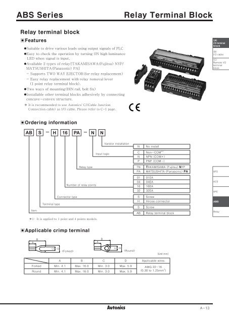
<strong>Relay</strong> terminal block<br />
▣Features<br />
•Suitable to drive various loads using output signals of PLC<br />
•Easy to check the operation by turning ON high luminance<br />
LED when signal is input.<br />
•Available 2 types of relay[TAKAMISAWA(Fujitsu) NYP/<br />
MATSUSHITA(Panasonic) PA]<br />
- Supports TWO WAY EJECTOR(for relay replacement)<br />
- Easy relay replacement with relay removal lever<br />
(1 point relay terminal block).<br />
•Two ways of mounting(DIN rail, bolt fix)<br />
•Installable other terminal blocks adhesively by connecting<br />
concave-convex structure.<br />
※ It is recommended to use Autonics' CJ(Cable Junction<br />
Connection cable) as I/O cable. Please refer to C-1 page.<br />
(A)<br />
I/O terminal<br />
block<br />
(B)<br />
I/O cable<br />
(C)<br />
Remote I/O<br />
terminal<br />
block<br />
▣Ordering information<br />
AB S H 16 PA N N<br />
Varistor installation<br />
N<br />
No install<br />
Input logic<br />
C Non-COM ※1<br />
N NPN (COM+)<br />
P PNP (COM-)<br />
<strong>Relay</strong> type<br />
TN<br />
PA<br />
TAKAMISAWA (Fujitsu) NYP<br />
MATSUSHITA (Panasonic) PA<br />
AFS<br />
Number of relay points<br />
01 01EA<br />
04 04EA<br />
16 16EA<br />
32 32EA<br />
ACS<br />
AFE<br />
Item<br />
<strong>Terminal</strong> type<br />
Connector type<br />
S<br />
H<br />
S<br />
AB<br />
Screw<br />
Hirose connector<br />
Screw<br />
<strong>Relay</strong> terminal block<br />
<strong>ABS</strong><br />
<strong>Relay</strong><br />
※1: It is applied to 1 point and 4 points models.<br />
▣Applicable crimp terminal<br />
A<br />
B<br />
A<br />
B<br />
C<br />
D<br />
<br />
C<br />
D<br />
<br />
(Unit:mm)<br />
A B C D Applicable wires<br />
Forked Min. 4.1 Max. 16.0 Min. 3.0 Max. 5.9 AWG 22-16<br />
Round Min. 4.1 Max. 16.0 Min. 3.0 Max. 5.9 (0.30 to 1.25mm 2 )<br />
A-13
<strong>ABS</strong> <strong>Series</strong><br />
▣Specifications<br />
Model<br />
<strong>ABS</strong>-S01PA-CN <strong>ABS</strong>-S04PA-CN <strong>ABS</strong>-H16PA-NN(PN)<br />
<strong>ABS</strong>-S01TN-CN <strong>ABS</strong>-S04TN-CN <strong>ABS</strong>-H16TN-NN(PN)<br />
Rated voltage 24VDC ±10%<br />
<strong>ABS</strong>-H32PA-NN(PN)<br />
<strong>ABS</strong>-H32TN-NN(PN)<br />
※1 250VAC 2A, 30VDC 2A※1<br />
Rated load voltage & current 250VAC 3A, 30VDC 3A<br />
(2A/1point, 8A/1COM)<br />
Power<br />
consumption<br />
PA type Max. 10.5mA ※2 Max. 10.5mA ※2 /Max. 15.5mA ※3<br />
TN type Max. 8.5mA ※2 Max. 8.5mA ※2 /Max. 13.5mA ※3<br />
Output type<br />
1a contact relay output<br />
Number of output 1point 4point 16point 32point(8point/1COM)<br />
Number of connectors ─ 20pins 40pins<br />
Applicable wire Min. 1.25mm 2<br />
Insulation resistance<br />
Min. 1,000MΩ (at 500VDC megger)<br />
Dielectric strength<br />
2,000VAC 50/60Hz for 1 minute (between coil and contacts)<br />
1,000VAC 50/60Hz for 1 minute (between contacts of same polarity) ※4<br />
Vibration<br />
Mechanical 0.75mm amplitude at frequency of 10 to 55Hz(for 1 min.) in each X, Y, Z direction for 2 hours<br />
Malfunction 0.75mm amplitude at frequency of 10 to 55Hz(for 1 min.) in each X, Y, Z direction for 10 minutes<br />
Shock<br />
Mechanical<br />
500m/s 2 (50G) in X, Y, Z directions for 3 times<br />
Malfunction<br />
147m/s 2 (15G) in X, Y, Z directions for 3 times<br />
Ambient<br />
Environment<br />
-15 to 55℃, Storage: -25 to 65℃<br />
temperature<br />
Ambient humidity<br />
35 to 85%RH, Storage: 35 to 85%RH<br />
Material<br />
CASE & BASE: PA6, CASE & BASE: MPPO, CASE: MPPO, BASE: PA66(G25%)<br />
TERMINAL PIN: Brass TERMINAL PIN: Brass<br />
TERMINAL PIN: Brass<br />
Tightening torque<br />
0.4 to 0.6 N·m<br />
Accessory<br />
─<br />
Jumper Bar: 2EA Jumper Bar: 2EA<br />
(Model No: JB-7.62-04) (Model No: JB-7.62-08)<br />
─<br />
Approval<br />
Unit weight<br />
PA type Approx. 21.5g Approx. 68g Approx. 224g Approx. 345g<br />
TN type Approx. 22.2g Approx. 71g Approx. 235g Approx. 370g<br />
※1: <strong>Relay</strong> contact capacity for resistive load.<br />
※2: The power consumption including LED current by one relay.<br />
※3: The power consumption including power LED current of‘※2’.<br />
▣Dimensions<br />
•<strong>ABS</strong>-S01PA-CN / <strong>ABS</strong>-S01TN-CN<br />
9<br />
10<br />
36<br />
38.5<br />
2-ø4<br />
72<br />
82<br />
88.5<br />
※4: For TN type(Fujitsu relay), it is 750VAC.<br />
※Environment resistance is rated at no freezing or condensation.<br />
•<strong>ABS</strong>-S04PA-CN / <strong>ABS</strong>-S04TN-CN<br />
2-Φ4.5<br />
79<br />
35.2<br />
70<br />
72<br />
•Jumper Bar<br />
7.62<br />
[ N ]<br />
2.7<br />
3.2 0.8<br />
9.5<br />
10.9<br />
35.2 ±0.2<br />
75.2<br />
10<br />
7.62 5.9 16-M3<br />
32<br />
Model<br />
Number of<br />
pins<br />
JB-7.62-04 JB-7.62-08<br />
4EA<br />
8EA<br />
[ N ] Size 29.5 60.0<br />
38<br />
•<strong>ABS</strong>-H16PA-□N / <strong>ABS</strong>-H16TN-□N<br />
A<br />
B<br />
4-Φ4.5<br />
•<strong>ABS</strong>-H32PA-□N / <strong>ABS</strong>-H32TN-□N<br />
84<br />
11<br />
79<br />
35.2<br />
70<br />
72<br />
5.9 7.62<br />
34-M3(<strong>ABS</strong>-H16)<br />
40-M3(<strong>ABS</strong>-H32)<br />
34<br />
37<br />
<strong>ABS</strong>-H16 type <strong>ABS</strong>-H32 type<br />
A 140 173<br />
B 70 100<br />
(Unit:mm)<br />
A-14
<strong>Relay</strong> <strong>Terminal</strong> <strong>Block</strong><br />
▣Wire connections<br />
•<strong>ABS</strong>-S01PA-CN / <strong>ABS</strong>-S01TN-CN<br />
(-)<br />
2<br />
INPUT (+)<br />
1<br />
•<strong>ABS</strong>-S04PA-CN / <strong>ABS</strong>-S04TN-CN<br />
(-) (-) (-) (-)<br />
4 3 2 1<br />
INPUT (+) (+) (+) (+)<br />
8 7 6 5<br />
(A)<br />
I/O terminal<br />
block<br />
(B)<br />
I/O cable<br />
(C)<br />
Remote I/O<br />
terminal<br />
block<br />
OUTPUT<br />
4<br />
RY1<br />
3<br />
RY4 RY3 RY2 RY1<br />
OUTPUT 12 11 10 9<br />
16 15 14 13<br />
•<strong>ABS</strong>-H16□-NN<br />
Connectors<br />
2<br />
1<br />
3 4 1 2 20 18 16 14 12 10 8 6 19 17 15 13 11 9 7 5<br />
20<br />
19<br />
※Hirose connector model no.<br />
: HIF3BA-20PA-2.54DSA<br />
<strong>Terminal</strong>s<br />
24VDC<br />
R1+ R2+ R3+ R4+ R5+ R6+ R7+ R8+ R9+ R10+ R11+ R12+ R13+ R14+ R15+ R16+<br />
GND R1- R2- R3- R4- R5- R6- R7- R8- R9- R10- R11- R12- R13- R14- R15- R16-<br />
•<strong>ABS</strong>-H16□-PN<br />
Connectors<br />
3 4 1 2 20 18 16 14 12 10 8 6 19 17 15 13 11 9 7 5<br />
AFS<br />
<strong>Terminal</strong>s<br />
ACS<br />
GND R1+ R2+ R3+ R4+ R5+ R6+ R7+ R8+ R9+ R10+ R11+ R12+ R13+ R14+ R15+ R16+<br />
24VDC R1- R2- R3- R4- R5- R6- R7- R8- R9- R10- R11- R12- R13- R14- R15- R16-<br />
AFE<br />
•<strong>ABS</strong>-H32□-NN<br />
Connectors<br />
2 40<br />
1<br />
1 3 2 4 40 38 36 34 32 30 28 26 24 22 20 18 16 14 12 10 39 37 35 33 31 29 27 25 23 21 19 17 15 13 11 9<br />
39<br />
※Hirose connector model no.<br />
: HIF3BA-40PA-2.54DSA<br />
<strong>ABS</strong><br />
<strong>Relay</strong><br />
<strong>Terminal</strong>s<br />
+24V +24V COM1<br />
R2 R4 R6 R8 R9 R11 R13 R15 COM3 R18 R20 R22 R24 R25 R27 R29 R31<br />
GND GND R1 R3 R5 R7 COM2 R10 R12 R14 R16 R17 R19 R21 R23 COM4 R26 R28 R30 R32<br />
•<strong>ABS</strong>-H32□-PN<br />
Connectors<br />
1 3 2 4 40 38 36 34 32 30 28 26 24 22 20 18 16 14 12 10 39 37 35 33 31 29 27 25 23 21 19 17 15 13 11 9<br />
<strong>Terminal</strong>s<br />
GND GND COM1 R2 R4 R6 R8 R9 R11 R13 R15 COM3 R18 R20 R22 R24 R25 R27 R29 R31<br />
+24V +24V<br />
R1 R3 R5 R7 COM2 R10 R12 R14 R16 R17 R19 R21 R23 COM4 R26 R28 R30 R32<br />
A-15
<strong>ABS</strong> <strong>Series</strong><br />
▣How to install jumper bar<br />
1)Cut the jumper bar for the desired length to fit<br />
cutting V groove with nipper, etc.<br />
2)Unfasten the terminal screws for common.<br />
Jumper bar cutting<br />
V groove<br />
3)Insert jumper bar under the unfastened terminal<br />
screws.<br />
4)Tighten all of screws upside the jumper bar.<br />
▣Installation<br />
◎Mounting to and Removing from DIN rail<br />
•Mounting<br />
1)Push rail lock to the direction "1".<br />
2)Hook DIN rail connector onto DIN rail.<br />
3)Push the unit down to the direction "2" and<br />
then push up the rail lock to the opposite<br />
direction "1".<br />
1<br />
1<br />
DIN rail<br />
connector<br />
DIN rail<br />
Rail lock<br />
•Removing<br />
1)Insert a screwdriver into hole of rail lock and<br />
pull the lock out to the direction "1".<br />
2)Removing the unit by pulling to the direction "2".<br />
2<br />
◎Mounting to panel<br />
1)This unit is able to mount on the panel with<br />
rail locks.<br />
2)It is recommended to use M4×15mm of<br />
spring washer screws and to use flat washers<br />
which are diameter ø6. The tightening torque<br />
should be 0.7 to 1.0N·m.<br />
◎Connection between units<br />
•<strong>ABS</strong>-S01PA-CN / <strong>ABS</strong>-S01TN-CN<br />
Connect between units with concave ( 凹 ) and<br />
convex ( 凸 ) parts to the direction '1'.<br />
1<br />
2<br />
※Example connection<br />
Rail lock<br />
A-16
<strong>Relay</strong> <strong>Terminal</strong> <strong>Block</strong><br />
▣How to replace relay<br />
•<strong>ABS</strong>-S01PA-CN / <strong>ABS</strong>-S01TN-CN<br />
1)Press relay removal lever to the direction '1' and<br />
inserted relay is come up.<br />
2)Remove this relay and lift up relay removal lever to<br />
the direction '2'.<br />
3)Check relay socket position and insert new relay to<br />
relay socket.<br />
※If pressing relay removal lever to right or left, this<br />
lever may be broken.<br />
1<br />
<strong>Relay</strong> removal<br />
lever<br />
<strong>Relay</strong><br />
<strong>Relay</strong> socket<br />
2<br />
<br />
(A)<br />
I/O terminal<br />
block<br />
(B)<br />
I/O cable<br />
(C)<br />
Remote I/O<br />
terminal<br />
block<br />
•<strong>ABS</strong>-S04PA-CN / <strong>ABS</strong>-S04TN-CN<br />
•<strong>ABS</strong>-H16PA-□N / <strong>ABS</strong>-H16TN-□N<br />
•<strong>ABS</strong>-H32PA-□N / <strong>ABS</strong>-H32TN-□N<br />
◦The position of Two way ejector for relay replacement<br />
< TWO WAY EJECTOR ><br />
TAKAMISAWA(Fujitsu) RELAY replace position<br />
MATSUSHITA(Panasonic) RELAY replace position<br />
TWO WAY EJECTOR<br />
for relay replacement<br />
TWO WAY EJECTOR<br />
for relay replacement<br />
< <strong>ABS</strong>-S04 type ><br />
◦Mount and Remove TAKAMISAWA(Fujitsu) relay<br />
< <strong>ABS</strong>-H16 / <strong>ABS</strong>-H32 type ><br />
◦Mount and Remove MATSUSHITA(Panasonic) relay<br />
AFS<br />
ACS<br />
AFE<br />
< Remove FUJITSU relay ><br />
< Mount FUJITSU relay ><br />
< Remove FUJITSU relay ><br />
< Mount FUJITSU relay ><br />
※<strong>Relay</strong> socket can be used both TAKAMISAWA(Fujitsu) relay (NYP24W-K) and MATSUSHITA(Panasonic)<br />
relay (PA1a-24V).<br />
<strong>ABS</strong><br />
<strong>Relay</strong><br />
▣Caution for using<br />
1. This unit shall not be used beyond specified temperature or humidity range.<br />
2. Maintain voltage fluctuations in the power supply within specified range.<br />
3. When connecting PLC or other controllers, check the polarity of power and COMMON before wiring.<br />
4. Use AWG 16(1.25mm 2 )wire and applicable crimp terminals to the terminal block.<br />
5. Turn OFF the power supply before wiring or removing connectors.<br />
6. Power shall be disconnected before replacing relay.<br />
7. Do not use this unit at below places.<br />
1 Place where there is severe vibration or impact.<br />
2 Place where strong alkalis or acids are used.<br />
3 Place where there are direct ray of the sun.<br />
4 Place where strong magnetic field or electric noise are generated.<br />
8. Installation environment.<br />
1 It shall be used indoor 2 Altitude Max. 2,000m<br />
3 Pollution Degree 2<br />
4 Installation Category II<br />
A-17