Operating manual 27.09.2011 CC Heating Thermostats - HUBER
Operating manual 27.09.2011 CC Heating Thermostats - HUBER
Operating manual 27.09.2011 CC Heating Thermostats - HUBER

Create successful ePaper yourself
Turn your PDF publications into a flip-book with our unique Google optimized e-Paper software.
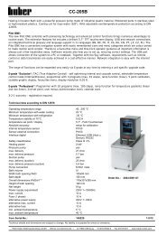
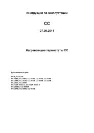
Valid for:<br />
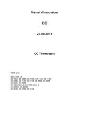
<strong>Operating</strong> <strong>manual</strong><br />
<strong>CC</strong><br />
<strong>27.09.2011</strong><br />
<strong>CC</strong> <strong>Heating</strong> <strong>Thermostats</strong><br />
<strong>CC</strong>-E, <strong>CC</strong>-E xd<br />
<strong>CC</strong>-106A, <strong>CC</strong>-108A, <strong>CC</strong>-110A, <strong>CC</strong>-112A, <strong>CC</strong>-118A<br />
<strong>CC</strong>-208B, <strong>CC</strong>-212B, <strong>CC</strong>-215B, <strong>CC</strong>-220B, <strong>CC</strong>-225B<br />
<strong>CC</strong>-202C, <strong>CC</strong>-205B<br />
<strong>CC</strong>-130A Visco 3, <strong>CC</strong>-130A Visco 5<br />
<strong>CC</strong>-200BX, <strong>CC</strong>-300BX<br />
<strong>CC</strong>-304B, <strong>CC</strong>-308B, <strong>CC</strong>-315B
Contents V1.8/09.11 // software: V06.10.001<br />
Foreword ............................................................................................................4<br />
Quick guide for <strong>CC</strong>-thermostats.............................................................................5<br />
Chapter 1: Safety ................................................................................................7<br />
Description of Safety and Information symbols ........................................................8<br />
Intended Use and General Safety Instructions..........................................................9<br />
Description ....................................................................................................... 10<br />
Duties of responsible person ............................................................................... 11<br />
Operator requirements........................................................................................ 11<br />
Machine operator duties ..................................................................................... 11<br />
Work area......................................................................................................... 11<br />
Safety Devices to DIN12876............................................................................... 12<br />
Additional Protection Devices .............................................................................. 14<br />
Environmental Conditions.................................................................................... 14<br />
<strong>Operating</strong> conditions .......................................................................................... 15<br />
Location ........................................................................................................... 16<br />
Thermal fluids ................................................................................................... 16<br />
Chapter 2: Electronics and operation .................................................................... 17<br />
<strong>CC</strong>-Pilot............................................................................................................ 18<br />
Information Displays <strong>CC</strong> ..................................................................................... 19<br />
Real-time clock .................................................................................................. 22<br />
Rechargeable Battery ...................................................................................... 22<br />
Event Function ............................................................................................... 22<br />
Operation <strong>CC</strong> .................................................................................................... 23<br />
<strong>CC</strong> Operation using the rotary knob ..................................................................... 24<br />
<strong>CC</strong> Operation using the simulated Number Pad ...................................................... 25<br />
Main menu........................................................................................................ 26<br />
Compact menu .................................................................................................. 27<br />
Comfort menu ................................................................................................... 35<br />
Com.G@te menu ............................................................................................... 42<br />
Function Numbers and their meaning.................................................................... 49<br />
User menu – config............................................................................................ 55<br />
User menu - select ............................................................................................. 56<br />
Chapter 3: Connect the machine, fill and prepare for the required application ............ 57<br />
Power connection .............................................................................................. 58<br />
Safety instructions............................................................................................. 58<br />
Start up............................................................................................................ 58<br />
Counter cooling (valid for <strong>CC</strong> <strong>Heating</strong> <strong>Thermostats</strong> with cooling coil) .................... 59<br />
Preperation for the operation of externally closed and externally open applications.. 59<br />
Operation as bath thermostat (valid for temperature control units with baths)............ 59<br />
Connecting an externally closed application (reactor).............................................. 60<br />
Switching on the temperature control unit ............................................................ 61<br />
Setting the over-temperature (OT) switch ............................................................. 61<br />
Setting the set-point limits .................................................................................. 64<br />
Entering a set-point ............................................................................................ 64<br />
Starting <strong>CC</strong> Temperature control.......................................................................... 64<br />
Ending <strong>CC</strong> Temperature control ........................................................................... 65<br />
2
Filling and air purging an externally closed system ................................................. 66<br />
Draining the machine and an externally closed application....................................... 67<br />
Changing thermal fluid / internal cleaning.............................................................. 67<br />
Chapter 4: Interfaces ......................................................................................... 68<br />
Interface modules (RS232/SERIAL, Com.G@te and Web.G@te) and Interface menus . 69<br />
RS232/SERIAL .................................................................................................. 71<br />
Mutual functions Com.G@te/Web.G@te............................................................... 72<br />
Specific functions Com.G@te.............................................................................. 74<br />
Specific functions Web.G@te.............................................................................. 75<br />
Chapter 5: First aid for a fault condition................................................................. 80<br />
Messages ......................................................................................................... 81<br />
Display Error Messages....................................................................................... 82<br />
Alarms and Warnings ...................................................................................... 82<br />
System Messages ........................................................................................... 82<br />
Alarm and Warning codes ................................................................................... 83<br />
Hard Alarms (not resettable)............................................................................. 83<br />
Exchange of the <strong>CC</strong> Electronics / Remote Control .................................................. 86<br />
Remote Control: .......................................................................................... 86<br />
Maintenance ..................................................................................................... 87<br />
Decontamination / Repair .................................................................................... 88<br />
Cleaning the surfaces ......................................................................................... 88<br />
Plug contacts .................................................................................................... 88<br />
Chapter 6: Taking the machine out of service........................................................ 89<br />
Decommissioning............................................................................................... 90<br />
Transport.......................................................................................................... 91<br />
Disposal ........................................................................................................... 91<br />
Appendix<br />
3
Foreword<br />
Dear Customer,<br />
The Huber team would like to thank you for ordering this product. You have made a<br />
good choice. We thank you for your trust!<br />
Please read and understand the instruction <strong>manual</strong> thoroughly before operating the unit.<br />
All instructions and safety information must be complied with.<br />
Please read this <strong>manual</strong> before transporting, commissioning, operating, maintaining,<br />
repairing, storing or disposing of this unit.<br />
Failure to comply with the instructions within this <strong>manual</strong> may invalidate any warranty<br />
for this unit.<br />
4
Quick guide for <strong>CC</strong>-thermostats<br />
Checklist for initial operation:<br />
1. Make sure that the machine is connected correctly and enough thermal fluid is<br />
inside.<br />
2. Switch on the unit via the mains switch!<br />
3. Make sure that the over-temperature is set correctly.<br />
4. Make sure that the set-point limits (min and max) are set correctly.<br />
5. Enter e.g. a new set-point!<br />
6. Make sure that you have set the correct temperature control mode (e.g.process)!<br />
7. Start temperature control!<br />
Operation:<br />
T-set button<br />
Press this button to<br />
enter a new setpoint.<br />
Compact menu:<br />
Display modes � Here you can select the graphic display.<br />
Comfort menu � Here one can have displayed the whole menu function.<br />
Program edit � Here you can edit a temperature program.<br />
Program start & stop � Here you can start / stop a temperature program.<br />
Pump settings � Here you can predefine a pump speed.<br />
Start ramp� Here you can predefine a temperature ramp.<br />
Control parameters � Here you can select/predefine control parameters.<br />
Set-point � Here you can predefine a set-point.<br />
Set-point limits � Here you can set set-point limits.<br />
Start&Stop � Here you can start / stop temperature control.<br />
Temperature control mode � Here you can select between jacket / process control<br />
Over-temp. Protection � Here you can set the over-temperature protection.<br />
Select user menu � Here you can select an individual menu.<br />
Exit �<br />
Button for main menu and menu selection.<br />
By pressing the rotary knob / encoder you can reach the<br />
compact menu with above mentioned functions.<br />
ESCAPE-Button<br />
To cancel a process (entry), press the ESC button.<br />
START / STOP-Button<br />
Here you can start / stop circulation, air-purge and<br />
thermoregulation.<br />
Setting the over-temperature protection:<br />
1. Select the function over-temperature from the compact menu!<br />
2. Select the menu point, setting the over-temperature protection!<br />
3. To adjust the over-temperature a code is being given out via the display for<br />
several seconds.<br />
4. You are being requested to enter a code!<br />
5. Enter the code which has been displayed previously!<br />
6. The over-temperature can be adjusted if the code has been entered correctly!<br />
7. The new over-temperature value will be now displayed!<br />
5
COM.G@TE allocation and setting (quick guide)<br />
6<br />
1<br />
2<br />
3<br />
5<br />
4<br />
6<br />
3<br />
2<br />
1<br />
3<br />
2<br />
1<br />
5<br />
1<br />
9 6<br />
POCO (potential free contact) Alarm plug-in connector<br />
Signal contact for external monitoring.<br />
The connection is designed as a potential free changeover contact.<br />
Normally open contact between pin 1 and pin 2. Normally closed contact between pin 2 and pin 3.<br />
Contact load: 1A at 24V DC Only use screened lines!<br />
AIF Reg-E-Prog Socket<br />
Analogue interface, one input channel (programmable) and 3 output channels.<br />
Pin Signal<br />
1. Current output, T extern 0/4-20mA or 0-10V<br />
2. Current output, set-point 0/4-20mA or 0-10V<br />
3. GND for analogue outputs GND<br />
4. Analogue input (programmable) 0/4-20mA or 0-10V<br />
5. Current output, free programmable 0/4-20mA or 0-10V<br />
6. GND for analogue input GND<br />
ECS Socket (External Control Signal) Standby<br />
Release signal ECS (External Control Signal), for starting / stopping temperature control.<br />
The following variants are offered:<br />
Pin Signal<br />
1,3 E2<br />
2 E1<br />
RS232 / RS485 Serial Socket<br />
Wiring RS232: Wiring RS485<br />
Pin2 RxD Receive Data Pin6 A with 120 Ohm load resistance<br />
Pin3 TxD Transmit Data Pin7 A<br />
Pin5 GND Signal GND Pin8 B<br />
Functions in connection with PLS<br />
Settings for analogue interface, release signal, signal contact and digital interface RS232 / RS485 can be made via the<br />
functions Analogue Interface, RS232 / RS485, ECS Standby and POCO Alarm in the COM.G@TE menu.<br />
Standard settings are:<br />
Analogue interface: analogue input OFF and analogue output OFF<br />
RS232 / RS485: RS232 with Baudrate 9600<br />
ECS Standby: no action<br />
POCO Alarm: no alarm<br />
Here you can determine a<br />
temperature / current range and<br />
predefine the current input value as<br />
set-point or speed of rotation!<br />
Here you can determine whether<br />
the temperature control unit is<br />
switched OFF/ON via an external<br />
switch contact!<br />
COM.G@TE:<br />
Analogue-Interface<br />
RS232/RS485<br />
ECS Standby<br />
POCO Alarm<br />
Return to main m...<br />
Here you can determine e.g. the<br />
dig. Interface, as well as baudrate<br />
and slave address with RS485!<br />
Here you can determine whether<br />
the unit reports a contact condition<br />
in case of a disturbance (alarm).
Chapter 1: Safety<br />
In this chapter is to be found the following sections:<br />
- Description of safety and information symbols<br />
- Intended use and General Safety Information<br />
- Description<br />
- Duties of the responsible person<br />
- Operator requirements<br />
- Machine operator duties<br />
- Work area<br />
- Safety Devices to DIN 12876 (applicable for units with heating)<br />
- Additional Protection Devices (if provided)<br />
- Environmental conditions<br />
- <strong>Operating</strong> conditions<br />
- Location<br />
- Thermal fluids<br />
7
Description of Safety and Information symbols<br />
8<br />
Safety information is shown with a pictogram and keyword.<br />
The keyword indicates the level of the corresponding danger.<br />
Danger!<br />
Warning!<br />
Caution!<br />
Information!<br />
Requirement!<br />
Immediate risk to the life and health of<br />
personnel (Serious injury or death).<br />
Possible risk to the life and health of<br />
personnel (Serious injury or death).<br />
Possible dangerous situation (possible injury<br />
to personnel or damage to property).<br />
User-tips and other useful information.<br />
Requirement to carry out a specific<br />
method, or action, for safe machine<br />
operation.
Intended Use and General Safety Instructions<br />
Danger!<br />
Non-intended use can result in considerable personal injuries and material damage.<br />
No third persons are authorized to make any changes to the machine. The device<br />
declaration becomes void, if any modification is carried out without manufacturers<br />
consent. Only personnel trained by the manufacturer may carry out modifications,<br />
repairs or maintenance work.<br />
The following must be observed:<br />
Always use the machine in a perfect working condition!<br />
Only expert personnel may initially start-up and repair the device!<br />
Do not bypass, bridge-over, dismantle or switch off the safety mechanisms!<br />
The manufacturer is not liable for damages caused by technical changes<br />
to the temperature control device, inappropriate handling and / or use of the<br />
temperature control device without regard to the operating instructions.<br />
The temperature control device is manufactured for commercial use only and may only<br />
be used to maintain the temperature of professionally expedient objects in laboratories<br />
and industry. Suitable thermal fluids are used throughout the entire system. The<br />
technical specifications of the temperature control device are determined in the data<br />
sheet. Operation must be prepared and carried out according to the operating<br />
instructions. Any non-observance of the operating instructions is considered as nonintended<br />
use.<br />
The temperature control device corresponds to the state-of-the-art and the recognized<br />
safety-related regulations. Safety devices are built into your temperature control device.<br />
The device is NOT approved for use as a medical product!<br />
This temperature control unit is NOT built as explosion-proof and is NOT<br />
suitable for use in "ATEX" areas!<br />
9
Description<br />
<strong>CC</strong> <strong>Heating</strong> <strong>Thermostats</strong> are machines that ideally can be used for temperature control<br />
tasks within an internal bath. The controller generation distinguishes itself by only using<br />
one hardware. On payment of a licence fee, an activation key can be obtained, so that<br />
the extended functions from a simple Basis Version to the Professional Version may be<br />
made available quickly and at any time. Please contact our customer support team<br />
(phone: +49 (0)781 9603244)<br />
The high performance heating technology, gives a very short heating time.<br />
With the integrated speed controlled pressure and suction pump circulation of the<br />
thermal fluid can be exactly adapted for the required application.<br />
With help of the self optimising cascade controller, you obtain the optimum control<br />
results under steady state conditions as well as by set-point changes. One can choose<br />
between aperiodic or with a small overswing (faster) control.<br />
Information and temperature development can be easily read via the large graphic<br />
display screen (with touch screen) as well as give command inputs.<br />
A comfortable menu guidance eases the operation of the machine.<br />
Dependent on your E-Grade Version, the following is available: analogue and digital<br />
interfaces, programmer, and a Pt100 connection (according to NAMUR).<br />
With the help of the digital interfaces RS232, RS485, the analogue 0/4-20mA or 0-10V<br />
interface as well as various digital in and output possibilities (all according to the<br />
NAMUR), the machine can be fitted without problem into many laboratory automation<br />
systems.<br />
The removable <strong>CC</strong>-Pilot can be used as a remote control.<br />
External temperature control requirements can be easily met (requirement E-Grade<br />
Exclusive or Professional) via the external Pt100 connection (NAMUR standard).<br />
The integrated temperature-ramp function as well as the internal programmer underline<br />
the high level of operator comfort. The integrated programmer offers the possibility of 3<br />
different temperature programs each with 5 program steps (E-Grade Exclusive) or 10<br />
different temperature programs with a maximum of 100 steps (E-Grade Professional),<br />
which can be made and then called up.<br />
The thermostat uses an over-temperature protection in accordance with DIN EN 61010-<br />
2-010, which is independent of the actual control circuits.<br />
10
Duties of responsible person<br />
The operating instruction is to be kept easily accessible and in immediate vicinity of the<br />
unit. Only suitably qualified personnel should operate this unit. Personnel should be<br />
properly trained before operating the unit. Make sure that the operators have read and<br />
understood the instruction <strong>manual</strong>. Supply appropriate Personal Protective Equipment as<br />
required.<br />
Operator requirements<br />
Only authorised personnel should operate this unit. Personnel should be properly trained<br />
before operating the unit. The minimum age for operators is 18 years. Personnel under<br />
18 years should only operate the unit under the direct supervision of qualified<br />
personnel. The operator is responsible for third parties within the working area.<br />
Machine operator duties<br />
Make sure that the operators have read and understood the instruction <strong>manual</strong>. Please<br />
observe the safety instructions. Appropriate Personal Protective Equipment (e.g. safety<br />
goggles, safety gloves) should be worn when operating the unit.<br />
Work area<br />
Work area is defined as the area in front of the machines control panel. Work area is<br />
determined by the peripheral equipment connected by the operator.<br />
It is the customer’s responsibility to ensure a clear, safe working area around the<br />
temperature control unit. The arrangement of the work area should be made after<br />
considering access to, and risk assessment of, the area and application.<br />
11
Safety Devices to DIN12876<br />
12<br />
- Low-liquid level protection<br />
- Adjustable over-temperature protection (also valid for chillers with heating)<br />
Table 2 – Classification of laboratory circulators and laboratory baths<br />
Class Heat transfer<br />
Technical requirement Marking<br />
designation liquid<br />
d<br />
I non-flammable a overheating protection c NFL<br />
II adjustable overheating protection<br />
flammable b adjustable over-temperature<br />
FL<br />
III<br />
protection and additional low-liquid<br />
level protection<br />
a<br />
Usually water; other liquids only if they are non-flammable within the temperature range<br />
in single fault condition<br />
b<br />
Bath liquids shall have a flash point ≥ 65 °C, this means if ethanol is used, only<br />
supervised operation is possible.<br />
c<br />
Overheating protection can be by using for example a suitable liquid level sensor or<br />
a suitable temperature limiting device.<br />
d Optional at the manufacturer`s discretion.<br />
Your temperature control unit is designated a Class III FL.<br />
The type and function of the over-temperature protection and low-level protection is<br />
dependent on the temperature control unit.<br />
Monitoring of the over-temperature is the same for all <strong>CC</strong>-<strong>Thermostats</strong>. As, there are<br />
models with two sensors and models with only one sensor.<br />
Two diferent types of low-level protection are available (depending on the model):<br />
1. Temperature control machines with classical float (e.g. ministats)<br />
2. Temperature control machines with an electronic low-level protection (e.g. K6cc-NR)
To 1. Temperature control machines with classcial float<br />
The most common and known type of level monitoring is the mechanical float. The float<br />
swims on the surface of the thermal fluid in the bath, and leads to a switching system.<br />
Depending on the level of the thermal fluid, the electronics will either signalize an OK<br />
state (with sufficient filling of the thermal fluid) or a non OK state (with insufficient<br />
filling of the thermal fluid). The float system function should be checked from time to<br />
time. In order to do this, whilst in standby mode, push the float in the bath downwards<br />
with a tool (e.g. screw driver). The electronics should then trigger an alarm.<br />
To 2. Temperature control machines with electronical low-level protection (ELO)<br />
ELO: Electronic over-temperature and low-level protection in combination<br />
Some temperature control machines (depending on the model) possess an electronic<br />
over-temperature and low-level protection. Instead of a mechanical float switch<br />
temperature sensors are mounted on the surface of the heating coils to monitor the<br />
over-temperature at a potential ignition source and to ensure that the critical<br />
temperature at the heating coils (burn point of the thermal fluid) is controlled by the<br />
controller (not valid for chillers, liquid level is determined by electrical capacity) via the<br />
graphical display (60) error message will be given out.<br />
A mechanical tool is no longer required to change the over-temperature settings. The<br />
over-temperature switch can only be adjusted after the user has re-entered a code<br />
displayed on the <strong>CC</strong>-Pilot´s display (60). This procedure avoids unintentional changes<br />
being made to the setting and replaces a mechanical tool by software.<br />
A new feature is the Process Safety function. This function provides further protection<br />
for the operators and application. A classic over-temperature device unit would trip and<br />
cause a shutdown if over-temperature cut-off temperature was reached. This could<br />
occur under circumstances where more heat was being generated by a process<br />
(exothermic) than the unit could remove. Switching the temperature control unit off<br />
would remove the only possible method of cooling the application down. Consequently,<br />
the temperature would be able to further increase, creating a risk of injury to personnel<br />
or damage to the application, for example by over-heating a liquid into pressurised<br />
vapour.<br />
Using the Process Safety function, the controller recognises when the over-temperature<br />
cut-off is reached, and switches the cooling on. The compressor automatic is<br />
automatically set to always on. Even if the temperature continues to rise, the<br />
refrigeration machine will increase its cooling to maximum to minimise the heating.<br />
Please also note chapter on Setting the over-temperature (OT) switch.<br />
13
Additional Protection Devices<br />
14<br />
- Auto-Start function<br />
- Alarm function<br />
- Warning messages<br />
- General unit messages<br />
Danger!<br />
Emergency Procedure: Disconnect Electrical Power!<br />
Turn the Mains isolator (36) to “0”!<br />
Dangerous liquid / vapours from temperature control unit or connected hoses (very hot,<br />
very cold, dangerous chemicals) and / or fire / explosion / implosion:<br />
Evacuate the area, following local regulations and procedures to prevent injury or loss<br />
of life! Refer to the MSDS Safety information for the thermal fluid concerned!<br />
Environmental Conditions<br />
This unit, and operations, will comply with DIN EN 61010-1:2001, only when it is<br />
located in suitable environmental conditions.<br />
- for indoor use only;<br />
- installation site ≤ 2000 m altitude;<br />
- installed on a level, even, non flammable surface;<br />
- maintain a clearance above and around the unit of 10 cm for water-cooled units,<br />
and 20cm for air-cooled units, to allow air to circulate around the unit;<br />
- for ambient temperature conditions please refer to the technical data sheet;<br />
remaining within these ambient conditions is imperative in ensuring accurate<br />
operation;<br />
- maximum relative humidity of 80% up to 32°C, decreasing linearly to 50%<br />
relative humidity at 40°C<br />
- use only as long a power cord as necessary;<br />
- the unit should be located so as not to restrict access to the mains power<br />
switch;<br />
- mains voltage should be ±10% of the rated value;<br />
- avoid voltage spikes;<br />
- transient voltage surges as they occur normally in the supply grid;<br />
- clean rating 2;<br />
- overvoltage category II
<strong>Operating</strong> conditions<br />
Please make sure that the application and system performance is dependent upon the<br />
temperature range, viscosity and flow rate of the thermal fluid:<br />
- Please ensure that the power supply connections are correctly dimensioned.<br />
- When choosing the thermal fluid, not only minimal and maximum<br />
temperatures have to be complied with but also have to be suitable regarding<br />
burn point, viscosity and / or freezing. Furthermore the thermal fluid has to be<br />
compatible with all the materials used in the unit.<br />
Please note following when using a pump adapter (optional) for external temperature<br />
control tasks:<br />
- Pressure changes with the length of hoses (keep as short as possible).<br />
Choose as large a diameter of hoses as possible (the width of the pump<br />
connections are considered as a point of reference) and may negatively affect<br />
temperature control results. Flow restrictions may occur if a too narrow<br />
connector is selected for corrugated hoses.<br />
- Please be aware of pressure drop in your connecting hoses when working<br />
with the lowest working temperature.<br />
- Please note that hose connections should be compatible with the thermal<br />
fluid used and the working conditions.<br />
- Pressure loss changes on the connections is dependent on length of hoses,<br />
diameter of hoses and fluid viscosity at the lowest working temperature.<br />
Flow restrictions may occur if too narrow a connector, valve is selected for<br />
corrugated hoses.<br />
- Do not kink the hoses<br />
- Check hoses in regular intervals for material fatigue (e.g. cracks).<br />
You may also achieve a contra cooling with water or cooling brine (optional)<br />
in connection with a cooling coil (accessories).<br />
Danger!<br />
If the cooling water contains high levels of minerals, e.g. chloride, bromide then suitable<br />
water treatment chemicals should be used. Use only recommended materials to<br />
maintain the unit warranty. Further information on corrosion, (appearance and<br />
avoidance) can be found on our website www.huber-online.com.<br />
Please refer to the sections on Intended Use and General Safety Instructions.<br />
15
Location<br />
16<br />
Caution!<br />
- Transport the unit upright<br />
- The unit should be mounted in an upright and secure position, on a solid, stable<br />
surface<br />
- Place on a non flammable surface<br />
- Keep the area around the unit clean, to avoid slip and trip hazards<br />
- Set the brakes on the castors once the unit is in position<br />
- Place suitable absorbent material under the unit to catch any condensate and<br />
thermal fluid spills<br />
- Any spillage of thermal fluid should be immediately cleaned up<br />
- For large units, check the weight / load capacity for the flooring<br />
Thermal fluids<br />
We recommend the thermal fluids shown in our catalogue. The name of a thermal fluid<br />
is derived from the working temperature range and the viscosity at 25 °C.<br />
Examples of thermal fluids in our catalogue:<br />
M40.165.10:<br />
� Lower working limit -40 °C<br />
� Upper working limit 165 °C<br />
� Viscosity at 25 °C: 10 mm 2 /s<br />
The data sheet for the thermal fluid used is of utmost importance, and must be read<br />
before use. This data sheet should be followed.<br />
� Please note the classification of your machine according to DIN 12876<br />
� The chosen thermal fluid must be compatible with stainless steel 1.4301 (V2A)<br />
and FKM!<br />
� The maximum viscosity of the thermal fluid may not exceed 50 mm²/s at the<br />
lowest temperature reached!<br />
� The maximum density of the thermal fluid may not exceed 1kg / dm³
Chapter 2: Electronics and operation<br />
The following sections are to be found in this chapter:<br />
- <strong>CC</strong>-Pilot<br />
- Information display<br />
- Real time clock<br />
- Operation<br />
- Operation using the rotary knob<br />
- Operation using the simulated Number Pad<br />
- Main menu points<br />
- Compact menu<br />
- Comfort menu<br />
- Com.G@te menu<br />
- Function numbers and their meaning<br />
- Configure user menus<br />
- Select user menus<br />
17
<strong>CC</strong>-Pilot<br />
18<br />
60<br />
63 64 65<br />
60) Touch screen and graphic display<br />
61) Key and rotary knob<br />
62) ESC key<br />
63) Key 1 (Soft-key 1)<br />
64) Key 2 (Soft-key 2)<br />
65) Key 3 (Soft-key 3)<br />
66) LED temperature display<br />
68) LED status display<br />
Locking<br />
66<br />
68<br />
61<br />
62
Information Displays <strong>CC</strong><br />
The following information displays are available:<br />
1. Graphical display (60)<br />
The most important display, giving details of standard parameters (set-point, current<br />
temperature, set-point limits), as well as menu options and error messages.<br />
2. LED temperature display (66)<br />
The green LED display shows the current temperature.<br />
Please note that in internal control mode the internal temperature (outlet temperature /<br />
jacket temperature) will be shown, and with cascade control mode the process<br />
temperature (reactor temperature) will be shown.<br />
3. LED status display (68)<br />
Information on the actual operating status of the temperature control unit (e.g.<br />
circulation is active, cooling machine is active, heating is active, process control is<br />
active).<br />
Screen display (this display is reached by selecting Main Menu / Display modes /<br />
Graphic)<br />
Field 13<br />
Field 12<br />
Field 11<br />
Field 10<br />
Field 9<br />
Field 8<br />
Field 7<br />
Field 6<br />
22.04.08<br />
07:35.20<br />
OT<br />
80.00<br />
delta T<br />
100.0<br />
Tmax.<br />
150.0<br />
Tmin.<br />
-35.0<br />
?<br />
T process 20.00<br />
T internal 19.50<br />
T set-point 15.00<br />
Funct.-no. Tset-point(F0) start<br />
Please also note operating options described in chapter operation.<br />
Field 1<br />
Field 2<br />
Field 3<br />
Field 4<br />
Field 5<br />
19
Description of individual Fields<br />
Field 1: Display Current value<br />
This field shows the current internal temperature of the unit and, if an external sensor is<br />
connected, the current process temperature.<br />
Field 2: Display set-point<br />
This field displays the current set-point.<br />
Field 3: Display Graphic temperature<br />
This field shows the internal and process temperatures in graphical format. The span of<br />
the temperature axis is between the minimum (see field 7) and maximum set-point<br />
limits (see also field 10).<br />
Field 4: Display Status Field<br />
This field shows useful information such as the current temperature control mode<br />
(internal or process), unit operations (degassing, air-purging) and active control loops.<br />
Field 5: Display Soft-keys operation<br />
This field enables various functions. Please therefore note the soft keys (63, 64, 65)<br />
located directly under the relevant touch screen buttons. The Function Number menu<br />
can be displayed by lightly touching the soft key 63 Funct.-no area of the screen.<br />
Please refer to the Function Numbers and Definitions chapter for more details.<br />
Pressing the soft key (64) Tset F(0) area of the screen will bring up the option to enter<br />
a new set-point. Pressing the soft key 65 Start of the screen will bring up the Start &<br />
Stop menu. This menu allows the temperature control, air-purging, circulation and<br />
degassing to be started as required. After an operation, the menu will return to the<br />
standard screen. Instead of the function Start in field 5 the function stop is now<br />
available. Pressing the soft key 65 Start of the screen will bring up the Start & Stop<br />
menu again. By pressing the Start area again, any operations previously started may be<br />
stopped.<br />
Field 6: Display Help<br />
Help (general information / trouble-shooting information) will be displayed.<br />
Field 7: Display minimum set-point<br />
This field displays the current minimum set-point limit (corresponds to Funct. no. F1).<br />
The minimum set-point also serves as the lower temperature limit for the graphic<br />
temperature display, in Field 3.<br />
Field 8: Pump and Level information<br />
This field displays the level as well as pump status including pump speed indication<br />
(only for temperature control devices with speed regulation).<br />
Field 9: Display maximum set-point<br />
This field displays the current maximum set-point limit (corresponds to Funct. no. F2).<br />
The minimum set-point also serves as the upper temperature limit for the graphic<br />
temperature display, in Field 3.<br />
20
Field 10: Display delta T<br />
This field displays the delta T value (max. admissible difference between process and<br />
internal temperature). This value may be set within a range of 0…100K under the main<br />
menu point limits / delta T limits. This field is active only with a connected process<br />
sensor and when the temperature control mode process temperature is activated.<br />
Field 11: Display Over-temperature cut-off<br />
This field displays the current setting of the over-temperature cut-off. Please note that<br />
this value can only be changed through the Main menu Over-temperature. Please refer<br />
to the Setting the over-temperature chapter in the Main menu.<br />
Field 12: Display Alarm and Warning messages<br />
This field displays information on any alarm or warning conditions that are present.<br />
Alarm and warning messages are also immediately displayed as text in the graphic<br />
display (60).<br />
Field 13: Display Date and Time<br />
This field displays the current date and time.<br />
21
Real-time clock<br />
Rechargeable Battery<br />
The Unistat Pilot as well as <strong>CC</strong>-Pilot (for temperature control devices with <strong>CC</strong>-Pilot) are<br />
equipped with an internal, battery-powered clock that runs even when the unit is turned<br />
off. When the unit is powered up, the actual date and time are uploaded to the unit.<br />
The capacity of the battery means allows the clock to continue to run for a number of<br />
months. If a unit has been powered-down for an extended time, it should be poweredup<br />
and left for an hour or so before running it again. If the time and date have been<br />
lost, they can be re-entered during this period.<br />
If after turning off and on again, the time and date have been reset, then it must be<br />
assumed that there is a problem with the rechargeable battery. In this case please<br />
contact our service department.<br />
Event Function<br />
The clock has a programmable event function. Using this function an operation can be<br />
set to run every day (until the function is reset in the operator menu). There are two<br />
available operations:<br />
Acoustic signal: The unit will generate an acoustic signal for about 15 seconds.<br />
Program Start: When configuring the calendar to start a program, the user will be asked<br />
for the number of the program to be started. The program will then be started at the set<br />
time and date, even if (<strong>manual</strong>) temperature control had not been previously started.<br />
22
Operation <strong>CC</strong><br />
Please note, there are multiple possibilities to operate the machine.<br />
1. Operation via function keys T1 to T3 (63, 64, 65), together with information<br />
given in the lowest line of the graphic display (60).<br />
2. Operation via the rotary knob / key (61)<br />
By pressing the key / rotary selector (61) one can choose the individual fields. By<br />
turning the key / rotary selector (61) one can enter directly the input mode.<br />
Leave this mode by pressing the ESC key.<br />
3. Operation via menu points<br />
By pressing the key / rotary selector (61) one enters the main menu. Choose the<br />
function required by turning the key / rotary selector (61). Confirm the input by<br />
pressing the key / rotary selector (61).<br />
The operational possibilities can be used in virtually any combination.<br />
Please note that the procedure presently being chosen can be broken off by using the<br />
ESC-key (62), and one then returns to the display which was selected under Display<br />
modes from the main menu.<br />
23
<strong>CC</strong> Operation using the rotary knob<br />
24<br />
Compact menu<br />
Display functions<br />
Comfort menu<br />
Enter program<br />
Program start & stop<br />
Pump settings<br />
Start ramp<br />
Control parameters<br />
Set-point<br />
Set-point limits<br />
Start & stop<br />
Temperature control mode<br />
Over-temperature protection<br />
User menu-select<br />
Once the rotary knob / key (61) has been pressed, the compact menu appears on the<br />
display screen. This menu lists the most commonly used options in alphabetical order.<br />
Turn the rotary knob / key (61) to highlight the required function and then press the<br />
knob to activate that function. An overview of these menu options is given in the Main<br />
menu chapter. Depending on the E-grade level, an upgrade can be made at any time<br />
with lower and middle levels, and the appropriate menu points will be displayed in the<br />
Graphic display (60). Please contact us at +49(0)781-9603100 or per e-mail under<br />
info@huber-online.com concerning information regarding upgrades.
<strong>CC</strong> Operation using the simulated Number Pad<br />
Function number menu Keyboard<br />
Function number 0<br />
Set-point<br />
New value<br />
F 0 Set-point<br />
^ v<br />
1 2 3<br />
4 5 6<br />
7 8 9<br />
ESC 0 OK<br />
Maximum value 50.00<br />
Minimum value -20.00<br />
1 2 3<br />
4 5 6<br />
7 8 9<br />
. 0 -<br />
ESC OK
Main menu<br />
The following functions are available:<br />
Compact menu Comfort menu<br />
Control parameters Acoustic alarm<br />
Comfort menu Auto-Start<br />
Display modes Clock<br />
Enter program Com.G@te (with connected Com.G@te only)<br />
Overtemperature protection Compact menu<br />
Pump settings Compressor automatic (not valid for all units)<br />
Set-point Control parameters<br />
Set-point limits Display functions<br />
Start & stop Display modes<br />
Start ramp E-Grade packages<br />
Temperature control mode Enter program<br />
User menu - select Factory default<br />
Exit Language<br />
Limits<br />
Overtemperature protection (for units with heating)<br />
Program start&stop<br />
Protection functions<br />
Pump settings<br />
Sensor adjustment<br />
Service<br />
Set-point<br />
Set-point limits<br />
Settings (others)<br />
Software version<br />
Start & stop<br />
Start ramp<br />
Temperature control mode<br />
Temperature scale<br />
Time scale<br />
User menu - config.<br />
User menu - select<br />
2nd set-point<br />
Web.G@te (with connected Web.G@te only)<br />
Exit<br />
The individual functions are described in the following pages:<br />
26
Compact menu<br />
Control parameters: The default setting is Automatic control parameter.<br />
CONFIGURATION MANUAL<br />
CONTROL PARAMETERS:<br />
Change control parameters<br />
Display control parameters<br />
Go back<br />
Control parameters<br />
KPInt. 181.3 200,0<br />
TNInt. 77.6 100,0<br />
TVInt. 0.0 0.0<br />
CONTROL PARAMETERS<br />
Internal<br />
Cascade jacket control<br />
Cascade process<br />
Go back<br />
Control and Ident. param.<br />
KPInt. 181.3 TtInt. 1.4<br />
TNInt. 77.6 TIInt. 7033.2<br />
TVInt. 0.0 KSInt 0.00<br />
SELECT THERMAL FLUID:<br />
No specification<br />
M120.08.02<br />
M90.200.02 (DW-Therm)<br />
M90.055.03 (Sil. oil)<br />
M40.165.10 (Sil.oil)<br />
FILLING QUANTITY:<br />
Please enter the approx. thermal<br />
fluid filling capacity<br />
Temperature control in a bath…<br />
…<br />
CONTROL PARAMETERS:<br />
Select auto./ <strong>manual</strong><br />
Config. automatic<br />
Config. <strong>manual</strong> param.<br />
Reset control parameters<br />
Display Parameter<br />
Return to main menu<br />
Select auto./ <strong>manual</strong><br />
Automatic control parameters<br />
AUTOMATIC CONFIGURATION:<br />
Find control parameters<br />
Control dynamics<br />
Display control parameters<br />
Fluid properties<br />
Go back<br />
THERMAL FLUID:<br />
Thermal fluid<br />
Circulation volume<br />
Bypass usage<br />
Show fluid<br />
Go back<br />
BYPASS:<br />
If there is a partial short cut<br />
through a bypass, please choose<br />
“yes”.<br />
AUTOMATIC / MANUAL<br />
SELECTION:<br />
Manual control parameters<br />
Automatic control parameters<br />
Go back<br />
AUTOMATIC MODE:<br />
Fast identification<br />
With preliminary test<br />
Estimate control parameters<br />
Go back<br />
CONTROL DYNAMICS:<br />
Fast, small OS<br />
Without overshoot<br />
Go back<br />
SHOW FLUID:<br />
Thermal fluid: M90<br />
Min. working temperature: [°C]:<br />
-90<br />
Characteristics: (zero)<br />
27
After selecting the main menu point Control parameters, the following functions are<br />
available:<br />
28<br />
� Select autom./<strong>manual</strong><br />
� Config. automatic<br />
� Config. <strong>manual</strong> parameters<br />
� Reset control parameters<br />
� Display parameters<br />
� Go back<br />
Select Autom. / Manual (Select Automatic / Manual)<br />
Application of the automatically detected or <strong>manual</strong>ly entered parameters, in order to<br />
regulate the temperature. We recommend the setting: Automatic control parameters!<br />
Config. Automatic (Automatic configuration)<br />
The following functions are available:<br />
� Find control parameters<br />
� Control dynamics<br />
� Display control parameters<br />
� Fluid properties<br />
� Go back<br />
Find control parameters<br />
Several options of controller parameterisation are available:<br />
1. Fast identification (valid as from E-Grade Exclusive)<br />
2. With preliminary Test (valid as from E-Grade Exclusive)<br />
3. Estimate control parameters (valid as from E-Grade Basic)<br />
1. Fast identification:<br />
Delivers a relatively fast and reliable control parameter with which a rapid regulation<br />
with a relatively high constancy can be reached.<br />
First, start temperature control and run for some minutes to achieve a suitable stable<br />
set-point. During the following do not carry out any changes on the system (e.g. filling /<br />
emptying the reactor core, change of agitator speed, change of the process sensor<br />
position etc.).<br />
After activating this function, a table with thermal fluids is displayed. Select the<br />
appropriate thermal fluid here. If your thermal fluid is not listed in the table, please<br />
select no specification. If your thermal fluid is not listed, the controller assumes a<br />
thermal fluid with characteristics, which normally results in an overshoot-free (slower)<br />
control. After selecting the thermal fluid, you are asked, whether you want to identify<br />
and control Internal or Process (cascade or set-point tracking). You are then requested<br />
to enter a set-point. Please note, that the identification is only successful, if the new<br />
set-point differs from the current set-point by at least 10 K. In the status field of the<br />
chart display (60), the information Temp. + Ident. active is displayed.
2. With preliminary Test:<br />
To achieve the best control results, select With preliminary Test in the controller<br />
settings. The control parameters will be identified within the limits of the min. and max.<br />
set-points. Temperature control will also take place at the set-point limits. Please be<br />
sure to have set these correctly. Depending on the temperature range, the parameter<br />
search will last correspondingly long.<br />
3. Estimate Control parameters:<br />
In comparison to other temperature control devices on the market which have a fixed<br />
control parameter set, we do however offer an additional feature: an estimated control<br />
parameter, which by selecting the thermal fluid and quantity, then using one of the<br />
parameter sets estimated for your application.<br />
Control dynamics<br />
After the control parameters are detected, control dynamics may be changed (see<br />
example below) without making new identification.<br />
You can select between faster regulation behaviour with a small overshoot (submenu<br />
point Fast, small OS) and a slower regulation behaviour without overshoot (submenu<br />
point Without overshoot). The default setting is “Fast, small OS”. The statement<br />
without overshoot only applies where any interfering action is small.<br />
120<br />
100<br />
80<br />
60<br />
40<br />
20<br />
Without overshoot Adjustment with overshoot<br />
120<br />
set point set point<br />
40<br />
actual value actual value<br />
0<br />
0 5 10 15 20 25 30 35 40 45 50<br />
100<br />
80<br />
60<br />
20<br />
0<br />
0 5 10 15 20 25 30 35 40 45 50<br />
The illustration above shows the transient response for change of set-point.<br />
Note, that you can change the regulation behaviour at any time without having to make<br />
a new controller parameter detection.<br />
Display control parameters<br />
You can have the automatically determined control parameters displayed here.<br />
Conf. <strong>manual</strong> control par. (Configuration <strong>manual</strong> control parameter)<br />
Control parameters can be enetered here. To carry out settings in this mode knowledge<br />
of control technology is required.<br />
Reset control param. (Reset control parameter)<br />
Control parameters can be reset to default setting with this function.<br />
29
Comfort menu<br />
Here one can switch to the whole range of functions.<br />
Please also note the chapter on Comfort menu, where further functions of the comfort<br />
menu are described.<br />
Display modes<br />
Following functions are available:<br />
30<br />
1. Standard: Values are displayed numerically (valid for all temperature control<br />
devices with Unistat Pilot and <strong>CC</strong>-Pilot).<br />
2. Graphic: Internal temperature, process temperature and set-point are displayed<br />
graphically – valid for Unistat Pilot. (with <strong>CC</strong>-Pilot only possible with Exclusive or<br />
Professional upgrade package).<br />
3. Device message: please see following example (valid for all temperature control<br />
devices with Unistat Pilot and <strong>CC</strong>-Pilot).<br />
4. Status Interfaces: Information on switch condition of e.g. ECS and POCO /<br />
ALARM (valid for all temperature control devices with Unistat Pilot and <strong>CC</strong>-Pilot).<br />
5. Large display: Values are displayed in large numerical format (valid for all<br />
temperature control devices with Unistat Pilot and <strong>CC</strong>-Pilot).<br />
6. Summary 1: Service information (valid for all temperature control devices with<br />
Unistat Pilot and <strong>CC</strong>-Pilot).<br />
7. Return to main menu<br />
Display modes is used to select the required display or information window (e.g. Status<br />
Interfaces or Device message). The standard setting is Graphic.<br />
Example: Display on choosing Device message.<br />
Date / Time of the<br />
Message<br />
Message in clear text<br />
Status information in<br />
clear text.<br />
Status information in<br />
clear text.<br />
10.04.06 3/100<br />
17:11:39<br />
Message-ID: -16427<br />
Actual status: 0x000F<br />
Pump running<br />
compressor stopped<br />
<strong>Heating</strong> on<br />
Manual set-point active<br />
2nd set-point not active<br />
Mains frequency. 50Hz detected<br />
230V AC 1 Phase<br />
Extended Status: 0x000D<br />
Compressor on<br />
Fan on<br />
Power isolation relays activated<br />
Message - counter<br />
Message - number<br />
Info: present Status<br />
Info: extended Status<br />
By turning the rotary knob / key (61) one can display the individual messages. Take<br />
note of the message counter for reference.
Example: Indication when choosing Large display<br />
L<br />
L<br />
e<br />
v<br />
e<br />
l<br />
TInternal °C<br />
TProcess °C<br />
Tset-point °C<br />
-20.5<br />
-20.1<br />
-20.0<br />
OT 35 °C<br />
Temperature control is<br />
active<br />
Enter program<br />
This corresponds to Function F20 in the Funct.-no. menu.<br />
Here it is possible to write new programs, or programs already written can be edited<br />
and changed or erased. (add segments, insert segments, delete segments or edit<br />
segments) or erase whole programs.<br />
Also one can set a particular behaviour at the end of the program through Stop temp.<br />
control, Continue temperature control (temperature is continued at the last set-point) or<br />
Repeat (the temperature program is restarted). One can also display the program<br />
elements as text or graphic. Working with the program creator will be described below.<br />
31
32<br />
Please enter<br />
Crystalisation<br />
1 2 3 4 5 6 7 8 9 0<br />
q w e r t z u i o p ü<br />
a s d f g h j k l l ö ä<br />
y x c n m<br />
COMPACT MENU:<br />
.<br />
.<br />
Enter program<br />
.<br />
.<br />
Select Program:<br />
Program 1<br />
.<br />
Program 10<br />
Return to main menu<br />
Program 01 contains<br />
00 segments<br />
SELECT ITEM:<br />
Segments<br />
Segments (List)<br />
End condition<br />
Input program name<br />
Delete program<br />
Return<br />
AT PROGRAM-END:<br />
Stop temperature control<br />
Continue tmp. control<br />
Repeat<br />
Return<br />
Segment 1<br />
Seg.: 1 2 3 4 5<br />
SP: 20,00°C Time/min: 1<br />
Mode: internal Stability: Temp<br />
AIF OUT: off AIF%:0<br />
Funct.: linear Tconst./ min 0<br />
POCO: off<br />
DEL INS BACK<br />
Segment 1<br />
Seg.: 1 2 3 4 5<br />
SP: 20,00°C Time/min: 1<br />
Mode: internal Stability: Temp<br />
AIF OUT: off AIF%:0<br />
Funct.: linear Tconst. / min 0<br />
POCO: off<br />
Save<br />
Seg. SP: time Mode: Stab.<br />
1 25,00 1 intern time<br />
2 30,00 5 process Temp<br />
press+turn to change column<br />
DEL INS BACK
To create a new program, continue as follows:<br />
1. Select the menu point Enter program from the Compact / Comfort menu.<br />
2. Select the program number to be used. Information on the number of segments<br />
from the program currently used etc is shown in the lower part of the graphic<br />
display screen (60).<br />
3. After having selected the program to be edited you are being offered several<br />
functions. Normally you would start with the sub menu<br />
a. Segments.<br />
Confirm by pressing the key / rotary knob (61). The cursor (frame) first indicates<br />
the set-point (SP). By turning the key / rotary knob (61) the individual functions<br />
such as (segment time, temperature control mode…) can be chosen. The<br />
activated function (frame) can be modified and saved by turning to the desired<br />
value and pressing the key / rotary knob (61). Please note, that when selecting<br />
an exponential ramp function (E-Grade Professional) the end value (more<br />
precisely 99% of the end value) will be reached after 5 times the time constant<br />
has elapsed. After having made all inputs select “SAVE” and confirm by pressing<br />
the key / rotary knob (61) to save the segment.<br />
By means of the function (soft-key) “DEL”, “INS” and “BACK” segments may be<br />
inserted easily and deleted. Choose the segment to be deleted by turning the key<br />
/ rotary knob (61) or to insert a new segment.<br />
or<br />
b. Segments (List).<br />
The main functions set-point (SP), time, mode and stability are listed for entry<br />
and modification. Lines are being chosen by turning the key / rotary knob (61)<br />
and columns by simultaneously turning and pressing of the key / rotary knob<br />
(61).<br />
The activated function (frame) can be modified and saved by pressing further<br />
turning to the desired value and pressing again the key / rotary knob (61).<br />
By means of the function (soft-key) “DEL”, “INS” and “BACK” segments may be<br />
easily inserted and deleted. Choose the segment to be deleted by turning the key<br />
/ rotary knob (61) or to insert a new segment.<br />
4. Via the sub menu point End condition, available options for the end of the<br />
program (e.g. Stop temperature control, or Continue temperature control) can be<br />
chosen.<br />
5. A new program name can be entered from the menu point Input program name<br />
by means of the keys from the touch screen (60).<br />
6. To delete a program, use the Delete program option from the sub menu.<br />
7. After entering a program, the Program start & stop option from the main menu<br />
can be used to call up, run and stop it. An early stop to the program can also be<br />
achieved by selecting the main menu point Program start & stop.<br />
33
Over-temperature protection<br />
Cut-off limits can be set in the heating chamber / heating. Please note chapter on<br />
setting the Overtemperature protection (OT).<br />
Program Start & stop<br />
Corresponds to function F23 in the Funct. No. menu. Here you can start, interrupt or<br />
end a program. If the temperature control machine has a Com.G@te connected,<br />
then the graphics display (60) will give a notice concerning the POCO/Alarm, as well as<br />
the analogue interface at program start. Please also note the sections on POCO/Alarm<br />
and on the analogue interface.<br />
Pump settings<br />
Settings and status information on pump.<br />
Set-point<br />
This corresponds to Function F0 in the Funct. no. menu.<br />
The set-point is limited to the band between the upper and lower set-point limits.<br />
The following is true:<br />
minimum set-point
Comfort menu<br />
Acoustic alarm<br />
Here you have the option to activate / deactivate the acoustic signal output.<br />
Auto-Start (after power on)<br />
This corresponds to Function F5 in the Funct.-no. menu. This allows the start-up<br />
condition, after mains failure to be defined.<br />
The following is true:<br />
OFF / Standby<br />
After power loss � Temperature control will not be restarted when power restored<br />
(Default setting)<br />
ON / Temp. control active<br />
After power loss � Temperature control will be restarted on return of power<br />
Power failure automatic<br />
After power loss � Return on power the settings previously set will be taken over<br />
Caution!<br />
The end-user should assess the risk and consequences for their application and select<br />
one of these three functions. The default setting is OFF.<br />
Clock<br />
Sets the unit Time and date. A number of functions can be chosen, e.g. a calendar /<br />
reminder function and timed start can also be configured.<br />
CLOCK FUNCTIONS:<br />
Set time<br />
Set date<br />
Autom. summer time<br />
Set alarm clock<br />
Alarm clock function<br />
Return to main menu<br />
Date : 13.05.08<br />
Time: 09:39:30<br />
Alarm clock date: 18.05.00<br />
Alarm clock time: 04:30:00<br />
Action: Program 1 Start<br />
FUNCTION ALARM CLOCK:<br />
No function<br />
Acoustic signal<br />
Program start<br />
Set alarm clock<br />
Return to main menu<br />
Example: Set alarm clock<br />
First enter the temperature programme via the main menu point clock / alarm clock<br />
function / acoustic signal. The acoustic signal will be given out when the time (date) is<br />
set via the function clock / action alarm clock / set alarm clock.<br />
35
Compact menu<br />
Here one can switch to the limited possibilities of the compact menu.<br />
Compressor Automatic<br />
Corresponds to Function F35 in the Funct.-no. menu. This is used to select the<br />
operating mode of the compressor. The default setting is always on.<br />
Automatic:<br />
The compressor control is set to switch on and off as required by the unit.<br />
Benefit: Energy saving<br />
Disadvantage: Longer response times to sudden increase in cooling demand.<br />
Always on:<br />
The compressor is always running, so the refrigeration machine is always immediately<br />
available.<br />
Always off:<br />
The compressor is always off.<br />
Compressor Automatic has to be switched to always on when setting process safety in<br />
the main menu point over-temperature protection / OT Mode (only valid for units with<br />
compressors).<br />
Control parameters<br />
A description on this point can be found in the chapter on Compact menu.<br />
Display functions<br />
Following functions are available:<br />
36<br />
1. The brightness of over-temp. and temperature 7-segment displays can be<br />
adjusted here.<br />
2. Warnings (<strong>manual</strong> confirmation or automatic confirmation)<br />
3. Messages (<strong>manual</strong> confirmation or automatic confirmation)<br />
4. Inactive menu items (display / unmask inactive menu items)<br />
5. Temperature resolution (0.01 °C, 0.1 °C)<br />
6. Brightness TFT backlight<br />
7. Go back<br />
Display modes<br />
A description on this menu point can be find in the chapter Compact menu.<br />
E-Grade packages<br />
Here you can enter your activation key in order to extend the functionality of the<br />
controller.
Enter program<br />
A description on this menu point can be found in chapter Compact menu.<br />
Factory default<br />
This section allows the different areas of the temperature control unit to be reset to the<br />
factory default. This can be a relatively quick way of changing the unit settings.<br />
Unit control data:<br />
Resets the set-points, set-point limits, temperature control mode, to the factory-set<br />
default values. Settings in the user menu and programs created using the programmer<br />
remain unchanged.<br />
User menus:<br />
Resets the complete user menus to their default settings. Settings in the unit data and<br />
programs created using the programmer remain unchanged.<br />
Programmer:<br />
Resets complete programs to default settings. Settings in the unit data and user menus<br />
remain unchanged.<br />
All together:<br />
Resets the unit data, user menu, program, and controller parameters to default values.<br />
Language<br />
This corresponds to Function F90 in the Funct. No. menu, and allows the unit’s<br />
operating language to be selected. The language options displayed are available.<br />
Limits<br />
The following functions are available:<br />
1. Delta T limit (limitation of the jacket temperature to the reactor temperature)<br />
2. Maximum heating power (limitation of the heating power in % steps)<br />
3. Maximum cooling power (limitation of the cooling power in % steps)<br />
4. Go back<br />
You can here set the maximum allowable difference (Delta T limits) between the<br />
internal temperature (jacket temperature) and the process temperature when using<br />
process control. If the chosen temperature difference is reached, then the temperature<br />
control device power is reduced so that this temperature difference is held. This<br />
function can protect the application (e.g. glass reactor) against thermal stress caused<br />
by too high a Delta T.<br />
Over-temperature protection (valid for units with heating)<br />
A description on this menu point can be found in the chapter on Compact menu.<br />
Program start & stop<br />
A description on this menu point can be found in chapter Compact menu.<br />
37
Protection functions<br />
Following functions are available:<br />
1. Internal sensor high limit alarm<br />
2. Internal sensor low limit alarm<br />
3. Process sensor high limit alarm<br />
4. Process sensor low limit alarm<br />
5. Warning time level (only valid for immersion thermostat <strong>CC</strong>-E and combinations using<br />
the immersion thermostat <strong>CC</strong>-E)<br />
6. Go back<br />
Int. high lim. alarm: (Internal sensor high limit alarm)<br />
Corresponds to the Function F108 in the Function-no. menu.<br />
The temperature monitoring is first activated when the internal (or process) temperature<br />
is below the maximum temperature limit. The temperature must “dip” into the limit<br />
band by 3 K, before an alarm will be triggered. If the temperature limits are below room<br />
temperature, the unit temperature must first reach the temperature band before the<br />
monitoring is activated. This method allows the monitoring temperature to be easily<br />
checked and changed. An alarm is displayed if the temperature value set here is<br />
exceeded for more than 3 seconds.<br />
NOTE: The default setting is set to a value that lies few degrees above the upper<br />
temperature limit of the machine.<br />
Int. low lim. alarm (Internal sensor low limit alarm)<br />
Corresponds to the Function F109 in the Function-no. menu.<br />
An alarm is given when the measured temperature is lower than the set limit values for<br />
more than 3 seconds.<br />
NOTE: The default setting is set to a value that lies few degrees below the lower<br />
temperature limit of the machine.<br />
Proc. high lim. alarm (Process sensor high limit alarm)<br />
Corresponds to the Function nr. F106 in the function menu.<br />
An alarm is displayed if the temperature value set here is exceeded for more than 3<br />
seconds. NOTE: The default setting is set to a value that lies few degrees above the<br />
upper temperature limit of the machine.<br />
Proc. low lim. alarm (Process sensor low limit alarm)<br />
Corresponds to the Function nr. F107 in the function menu.<br />
An alarm is given when the measured temperature is lower than the set limit values for<br />
more than 3 seconds.<br />
NOTE: The default setting is set to a value that lies few degrees below the lower<br />
temperature limit of the machine.<br />
38
Warning time level<br />
As low-level protection you can enter a warning time until the actual switching off of<br />
the temperature control unit. In case of low-level, a signal will be sent out (you<br />
therefore have to set the signal to ON in the main menu point Acoustic alarm). Level<br />
indication will be displayed in red. A switch off, however, will take place after the<br />
warning time has elapsed. This function allows you to refill thermal fluid before it<br />
comes to a switch off due to low fluid level.<br />
Pump settings<br />
A description on this menu point can be found in chapter Compact menu.<br />
Sensor adjustment<br />
There exists a possibility to carry out an adjustment of the internal sensor, the process<br />
sensor and the return sensor. We recommend to consult our service department before<br />
carrying out any adjustments of the internal sensor and return sensor (not valid for all<br />
units). An adjustment is only necessary, if due to ageing of sensors measuring is<br />
inaccurate or insufficient. There are different reasons for inaccuracy of the process<br />
sensor, e.g. non-linearity, contact resistance. The new generation thermoregulation<br />
units give you the opportunity to carry out different adjustments. If the inaccuracy<br />
applies over the whole temperature range, adjustment should be carried out only at one<br />
point (offset adjustment). If accuracy is not constant over whole temperature range we<br />
recommend an adjustment of up to 5 spots. The more spots are included the better are<br />
the measuring results afterwards.<br />
For adjustments you will need a reference thermometer with corresponding accuracy.<br />
The sensor of the thermometer has to be positioned as close as possible to the process<br />
sensor.<br />
Settings for the process sensor<br />
Start thermo control and enter a set-point, which serves as first adjustment point.<br />
After set-point is reached, wait until the temperature is constant. Choose the menu<br />
point Sensor adjustment / Adjust process sensor / New adjustment point from the<br />
comfort menu. Two sub-menus are available.<br />
Current temperature: Adjustment of the current measured temperature by input of the<br />
reference value.<br />
Other temperature: Input of a previously measured temperature pair.<br />
Service<br />
This menu is only available in service mode, and may only be accessed after contacting<br />
Huber. It allows the unit’s internal sensors and other data to be directly read, for service<br />
purposes.<br />
39
Set-point<br />
A description on this menu point can be found in the chapter on the Compact menu.<br />
Set-point limits<br />
A description on this menu point can be found in the chapter on Compact menu.<br />
Settings (others)<br />
Here, information concerning your application may be entered or read out. The values<br />
input here will be considered when controller parameterisation is taking place (please<br />
see chapter on Control parameters)<br />
The following functions are available under the menu point Change thermal fluid:<br />
40<br />
1. Thermal fluid (choose thermal fluid)<br />
2. Circulation volume (indication on volume to be temperature controlled)<br />
3. Bypass usage<br />
4. Show fluid (values and information on thermal fluid are being displayed)<br />
5. Back<br />
Under the menu point Bath selection different bath volumes can be chosen. Please<br />
select accordingly.<br />
Software version<br />
Corresponds to Function F98 in the Function-no. menu.<br />
The installed software version of the electronics are displayed.<br />
petite fleur<br />
Serial Number: 77507<br />
LoadCode: 803261629<br />
Create Conde : 708020946<br />
<strong>CC</strong>-Pilot: V06.10.001<br />
Jan 12 2010 16:38:15<br />
Serial Number : 36<br />
Control: V05.10.001 1201<br />
Jan 12 2010 16:38:15<br />
Serial Number : 747<br />
Continue: Press Enconder<br />
button<br />
Start & stop<br />
A description on this menu point can be found in the chapter on Compact menu.<br />
Start ramp<br />
A description on this point can be found in the chapter on Compact menu.<br />
Temperature control mode<br />
A description on this menu point can be found in the chapter on Compact menu.<br />
Temperature scale<br />
It is possible to choose between °C, °F and K
Time scale<br />
The time display can be displayed in various formats (hh, min, sec).<br />
2 nd set-point<br />
Corresponds to the Function F4 in the Function-no. menu.<br />
The input of a 2 nd or alternative set-point is done in the same way as the normal<br />
set-point under the menu point set-point. This second set-point is activated with an<br />
external control signal (Function F28) or through a watchdog event<br />
User menu - select<br />
A description on this menu point can be found in the chapter on Compact menu.<br />
User menu - config.<br />
A description on this menu point can be found in the chapter on Compact menu.<br />
41
Com.G@te menu<br />
Here, the functions (analogue interface, RS232/RS485, ECS-Standby, POCO Alarm)<br />
used in connection with an external control (e.g process control system “PCS”) are<br />
listed.<br />
42<br />
ANALOGUE-INTERFACE:<br />
Config. input<br />
Config. output<br />
Go back<br />
USE EXTERNAL SIGNAL TO:<br />
No action<br />
Switch to 2nd setp.<br />
2nd set-point selectiv<br />
Internal / Process<br />
Temp. contr. on/off<br />
Enable machine<br />
Go back<br />
COM.G@TE:<br />
Analogue interface<br />
RS232/RS485<br />
ECS Standby<br />
POCO Alarm<br />
Return to main menu<br />
POCO ACTION:<br />
OFF<br />
Check act. value<br />
External Alarm<br />
Unipump/PCS<br />
Control by RS232<br />
Check process temp.<br />
Unipump with echo<br />
Programmerr<br />
Check int. temp. abs.<br />
Check proc. temp. abs.<br />
Go back<br />
DIGITAL INTERFACE:<br />
Select RS232/485<br />
Baud rate<br />
Slave address (LAI)<br />
Go back
Analogue Interface<br />
AIF INPUT FUNCTION:<br />
AIF ->Input off<br />
AIF ->Internal temp.<br />
AIF ->Process Temp.<br />
AIF ->Set-point<br />
AIF -><strong>Heating</strong> 0-100%<br />
AIF ->Power<br />
AIF ->Pump speed setp.<br />
AIF ->Pump press. setp.<br />
Go back<br />
ADJUST:<br />
Adj. current value<br />
Enter in table<br />
Go back<br />
Adjustment of the current<br />
measured value by input of the<br />
reference value<br />
ANALOGUE INPUT:<br />
Means:<br />
AIF -> Input off<br />
Action on analogue error:<br />
Switch off<br />
Action on cable break:<br />
Trigger an alarm<br />
Configuration In/Out<br />
4.00mA -> 274.0 °C<br />
20.00mA -> 274.0 °C<br />
Actual AIF input values:<br />
0 Bit -> 0.00mA->0.00 °C<br />
Continue: Press Encoder<br />
button<br />
ANALOGUE-INTERFACE:<br />
Config. input<br />
Config. output<br />
Go back<br />
ANALOGUE INPUT:<br />
AIF–Input - Function<br />
On cable break<br />
Cfg. input range<br />
Adjustment<br />
On analogue error<br />
Display AIF value<br />
Reset AIF input<br />
Show table values<br />
Current / voltage switch<br />
Filter constant<br />
Go back<br />
SHOW TABLE VALUES:<br />
ref. val meas. val<br />
P1 10485 10485<br />
P2 52428 52428<br />
WARNING:<br />
Following Parameters are going<br />
to be removed when resetting<br />
the analogue interface<br />
Measurement range<br />
Adjustment<br />
In / output function<br />
AIF FILTER CONST:<br />
Act. Setting: 0002<br />
Max. Setting 0010<br />
Min. Setting 0000<br />
New setting 0002<br />
CURRENT / VOLTAGE SWITCH:<br />
Current<br />
Voltage<br />
Go back<br />
ON CABLE BREAK:<br />
Trigger an alarm<br />
No alarm, normal operation<br />
Go back<br />
Temperature T1<br />
Actual setting: -40,00<br />
Max. setting 350,00<br />
Min. setting -150.00<br />
New value: : -40,0<br />
OK ESC<br />
OK KEYB<br />
Temperature T2<br />
Actual setting -40,00<br />
Max. setting 350,00<br />
Min. setting -150.00<br />
New value: -40,0<br />
ESC OK KEYB<br />
ON ANALOGUE ERROR:<br />
Switch off<br />
Act. 2 nd Set-point<br />
Go back<br />
43
Using the analogue interface, the unit can be controlled via an analogue (0/4-20 mA or<br />
0-10V) signal. An analogue (0/4-20 mA or 0-10V) output signal is also available. The<br />
schematic above describes the structure of the analogue input and output. Via the filter<br />
constant in the menu point analogue input it is possible to smooth a noisy input signal.<br />
Below is an example using the analogue input to provide a set-point, and the analogue<br />
output gives the process temperature. The current / temperature configuration is also<br />
shown.<br />
E.g. required operating temperature range is 0°C to 100°C. 0°C should correspond to<br />
4mA. 100°C to 20mA. The 4…20mA (I / O) is available on the analogue interface<br />
connector. An alarm should be given when the cable breaks. The unit should be<br />
switched off if there is an analogue error.<br />
44<br />
SOURCE ANALOGUE OUT:<br />
No output<br />
Set-point<br />
Internal temp.<br />
Process temp.<br />
Manual preset<br />
Programmer<br />
RS232 / 485<br />
Pump Press. act.<br />
Control Deviation<br />
Go back<br />
ADJUSTMENT:<br />
Adj. current value<br />
Enter in table<br />
Go back<br />
Adjustment of the current<br />
measured value by input of the<br />
reference value<br />
ANALOGUE-INTERFACE:<br />
Config. input<br />
Config. output<br />
Go back<br />
ANALOGUE OUTPUT:<br />
AIF-Output - range<br />
Cfg. input range<br />
Adjustment<br />
Reset AIF output<br />
Show table values<br />
Go back<br />
WARNING:<br />
Following Parameters are going<br />
to be removed when resetting<br />
the analogue interface<br />
Measurement range<br />
Adjustment<br />
In / Output function<br />
SHOW TABLE VALUES:<br />
ref. val meas. val<br />
P1 10485 10485<br />
P2 52428 52428<br />
OK<br />
Temperature T2<br />
Actual setting: -40,00<br />
Max. setting 350,00<br />
Min. setting -150.00<br />
New value: : -40,0<br />
ESC OK<br />
Temperature T2<br />
Actual setting -40,00<br />
Max. setting 350,00<br />
Min. setting -150.00<br />
New value: -40,0<br />
ESC OK<br />
KEYB<br />
KEYB
Settings:<br />
1. Settings on temperature / current range<br />
Select analogue interface / config. input / adjust measurement range<br />
Enter the temperature range to correspond to 0/4-20mA (T1=0 °C, T2=100<br />
°C).<br />
2. Select input signal<br />
Select the input signal (AIF-> set-point) via analogue interface / config. input /<br />
AIF-Input - Function<br />
3. Select output signal<br />
Select the output signal (Process temp.) via analogue interface / config. output /<br />
output range<br />
4. Select action if cable breaks<br />
Select analogue interface / config. input / on cable break<br />
Trigger an alarm.<br />
5. Select action upon analogue error<br />
Select analogue interface / config. input / on analogue error<br />
Switch off.<br />
6. The settings can be reviewed by selecting:<br />
analogue interface / config. input / display AIF values.<br />
Please note that the fine signal adjustment functions the same for the analogue output<br />
as it does for the input.<br />
Setting information for fine adjustment.<br />
General: When the machine is delivered and after a Reset (Reset AIF input) the interface<br />
will be set accurately enough. An adjustment is not necessarily required.<br />
It is possible at any time to adjust the precision of the input channel. This could be<br />
required if the set-point input current does not coincide with the expected temperature<br />
value. If as shown in point 1 above, an input of 4.000mA does not give exactly 0°C,<br />
but maybe 1°C. A fine adjustment can then be made. Change to menu point analogue<br />
interface / config. input / fine adjust / xxxxx. Feed 4.000mA into the interface. Confirm<br />
the value. Choose then analogue interface / config. input / fine adjust / xxxxx. Feed<br />
then 20.000mA into the interface. Confirm the value. At the end, a current input of<br />
exactly 4.000mA should give a set-point of 0°C and a current input of 20.000mA<br />
should give a set-point of 100°C.<br />
The fine adjustment of the output channel is done in a similar manner. A sensor value<br />
of 0°C and 100°C should give an output current value of 4.000mA and 20.000mA.<br />
45
RS232/RS485 (Digital Interface)<br />
Following functions are available:<br />
46<br />
1. Select RS232/485 (option between RS232 and RS485)<br />
2. Baudrate (selection of transmission speed)<br />
3. Slave address (Selecting a bus address, only when using RS485)<br />
4. Test dig. Interface (command TI is send via RS232)<br />
5. Go back<br />
ECS / Standby External control signal<br />
Corresponds to Function F28 in the Funct.-no. menu.<br />
This is a potential free input. A closed contact switches e.g. temperature control on,<br />
and an open contact switches e.g. temperature control off.<br />
Please also refer to the Com.G@te section of this <strong>manual</strong>.<br />
Following functions are available:<br />
1. No action<br />
2. Switch to 2 nd set-point<br />
3. 2 nd set-point selective<br />
4. Internal / Process<br />
5. Temperature control ON / OFF<br />
6. Release<br />
* No action:<br />
A switch of the contacts open / closed or closed / open has no effect.<br />
* Switch to 2 nd set-point<br />
Switching the closed contact to open contact causes the unit to use the value of the<br />
second set-point. A further switch from open to closed contact causes the unit to<br />
continue temperature control at the second set-point.<br />
* 2 nd set-point selective<br />
An open contact causes the unit to use its internal set-point. A closed contact causes<br />
the unit to use the value of the second set-point.<br />
* Internal / Process<br />
A closed contact causes the unit to immediately switch e.g. between internal and<br />
external control mode. An open contact causes the unit to switch back to its original<br />
control mode.<br />
* Temperature control ON / OFF<br />
Switching from open to closed contact causes the unit to start temperature control.<br />
Switching from closed to open contact causes the unit to stop temperature control.<br />
* Release<br />
Switching from closed to open contact while temperature control is operating causes<br />
the unit to stop temperature control. Switching back from open to closed contact does<br />
not start the unit.
POCO alarm Pot. free Contact (POCO)<br />
Corresponds to Functions F6, F7, and F8. This function allows a relay contact, in the<br />
Com.G@te (46) to be controlled and activated. Please also review the Com.G@te<br />
section of the <strong>manual</strong>.<br />
The following functions are available:<br />
OFF:<br />
The POCO displays the OK status when the unit is ready to operate. This condition<br />
is after the internal controller check, approx. 30 sec. after the switch on. The OK status<br />
will be ended by switching off the mains or a fault.<br />
Check act. value.:<br />
The relay switches when the current internal temperature is outside the range set<br />
between the POCO minimum and maximum internal temperatures (F6 and F7). The<br />
values in functions F6 and F7 are relative to the current set-point. If the range is<br />
exceeded the potential free contact is switched (from the OK status), and the unit will<br />
continue to operate. If the actual value is in the range, the contact will be reset to the<br />
OK status.<br />
External alarm:<br />
The POCO relay is only activated if the unit is in “fault status” when it is switched on.<br />
This is so that the alarm is not raised when the unit gets switched off.<br />
If you wish the alarm function together with the work flow principle, please use the<br />
POCO function OFF.<br />
Unipump / PCS: (Unipump / Process Control System)<br />
This POCO function is used to connect the signal calling for the circulation pump to<br />
start with an external booster pump. This has to be done so that the external pump<br />
runs in synchronisation with the circulation pump in the unit, this means that the POCO<br />
activates (to the OK status) as soon as the circulation pump starts.<br />
PCS: An example of this would be when temperature control would be controlled by a<br />
“PCS" via the external control signal (Menu point External control signal or Function<br />
F28), the POCO can be used to communicate.<br />
Condition POCO ON means temperature control is activated.<br />
Condition POCO OFF means temperature control is not activated.<br />
Control by RS232:<br />
The relay is controlled via an RS232 command. Therefore please note our Huber-<br />
Software.<br />
Check process temperature.:<br />
A measured temperature check for the PROCESS SENSOR providing it is not the control<br />
sensor. The POCO relay switches when the current external, (process temperature) is<br />
outside the range set between the POCO minimum and maximum external<br />
temperatures.<br />
When the unit is set to internal control, and the POCO check process temperature” is<br />
selected, the temperature of the external sensor is monitored – this sensor can be<br />
independent of the internal temperature and the temperature control process. The limits<br />
set by F6 and F7 still apply.<br />
47
Unipump with echo:<br />
This function is used to monitor if the Unipump being controlled by the POCO is<br />
operating in synchronisation with the Unistat’s own pump. The operating status of the<br />
Unipump can be signalled via a normally open contact by connecting to a “level”<br />
connector. If the Unipump does not operate with the machine, a fault signal will be<br />
generated.<br />
This operating mode is very useful if the Unipump has to be monitored, either to<br />
guarantee the desired temperature control or to avoid unintended heating of the thermal<br />
fluid.<br />
Programmer:<br />
The relay is controlled by a command from a segment within a temperature profile<br />
running on the programmer. Please also note the menu point on Enter program.<br />
Check int. temp. abs. (check internal temperature absolute)<br />
The relay switches when the current internal temperature is outside the specific band<br />
determined by the maximum and minimum temperature limits. Outside this band POCO<br />
is active, within the band POCO is inactive.<br />
Check proc. temp. abs. (check process temperature absolute)<br />
The relay switches when the current external temperature is outside the specific band<br />
determined by the maximum and minimum temperatures. Outside this band POCO is<br />
active, within the band POCO is inactive.<br />
48
Function Numbers and their meaning<br />
A detailed description of the functions, as well as an alternate operation for the menu<br />
guide can be found in the chapter Compact-/ Comfort-/ Com.G@te menu<br />
F0 Set-point<br />
minimum set-point
F8 POCO - programming<br />
The options for the potential free contact are given and described in the earlier Potential<br />
free Contact section the Com.G@te menu of this <strong>manual</strong> (Pot. free Contact).<br />
F9 Control parameters<br />
Please see chapter Control parameters in the Compact menu for detailed description.<br />
F10 Machine messages<br />
Information on the machine about condition (status, warnings and faults).<br />
F12 Adj. internal sensor (Adjust internal sensor)<br />
Up to 5 free selectable temperature values for the adjustment of the internal sensor can<br />
be defined and adjustment may be carried out. Please also see description on Sensor<br />
adjustment in the chapter Comfort menu.<br />
F13 Adj. process. sensor (Adjust process sensor)<br />
Up to 5 free selectable temperature values for the adjustment of the process sensor can<br />
be defined and adjustment may be carried out. Please also see description on Sensor<br />
adjustment in the chapter Comfort menu.<br />
F14 Adj. return sensor (Adjust return sensor)<br />
Up to 5 free selectable temperature values for the adjustment of the return sensor can<br />
be defined and adjustment may be carried out. Please also see description on Sensor<br />
adjustment in the chapter Comfort menu.<br />
F18 Delta T limit<br />
Maximal admissible temperature difference between internal and process temperature.<br />
Once the maximum temperature difference has been reached, the unit will automatically<br />
reduce its cooling (or heating) capacity as required.<br />
F19 Ramp function<br />
The set-point default refers to, depending on the temperature control mode set<br />
(function F3) the internal sensor or process sensor.<br />
F20 Enter program<br />
You can enter the chosen temperature programme.<br />
F22 Program control<br />
Choose between following options: Start, Stop, Break, Skip to the end segment of a<br />
running temperature programme.<br />
F23 Program start<br />
Start of the temperature programme (calendar start).<br />
F27 Time scale<br />
Time scale in minutes or hours.<br />
F28 Ext. control signal (External control signal)<br />
The external control signal can be used to control one of a number of available unit<br />
functions. Please see chapter on Com.G@te menu.<br />
50
F30 Set date<br />
Setting the date.<br />
F31 Set time<br />
Setting the time.<br />
F33 Set over-temperature protection<br />
Setting the over-temperature protection. Please note chapter on setting the overtemperature<br />
switch.<br />
F34 Air purge<br />
Start / Stop air purge<br />
F35 Compressor automatic<br />
This is used to select the operation of the compressor: Default setting is always ON<br />
Automatic:<br />
The compressor automatic is set to switch on and off as required by the unit.<br />
Benefit: Energy saving<br />
Disadvantage: Longer response times to sudden increase in cooling demand.<br />
Always ON:<br />
The compressor is always running, so the refrigeration system is always immediately<br />
available.<br />
Always OFF:<br />
The compressor is always off.<br />
The compressor automatic (valid for units with compressors only) must be set to<br />
always on when selecting process security in the main menu<br />
Over-temperature protection / OT Mode<br />
F37 Temperature mode<br />
Setting the temperature mode.<br />
F39 Signal<br />
Activating the signal.<br />
F40 Test RS232<br />
Start / Stop<br />
F41 Select user menu<br />
Please refer to chapter select user menu.<br />
F42 Configure user menu<br />
Please refer to chapter configure user menu.<br />
F46 Define analogue input (function analogue input)<br />
This function allows an analogue input current of 0/4-20 mA or 0-10V to be assigned<br />
to an input value.<br />
51
F47 On cable break<br />
This function determines the unit’s response to a break in the cable, e.g. turn off<br />
temperature control, or control to a second set-point.<br />
F49 Unit name<br />
This function displays the unit model number.<br />
F50 Input password<br />
Used only for Service. Contact Huber for further information.<br />
F52 Factory default<br />
This functions allows to reset the unit to the factory default.<br />
F55 Degassing mode<br />
Activating the degassing mode. Please see the section on Degassing an external closed<br />
application.<br />
F60 Information on the machine<br />
In this function information on the machine can be obtained.<br />
F61 X-Information (Service)<br />
Xxxxxxxxxxxxxxxxxxxxxxxxxxxxxxxxxxxxxxxxxxxxxxxxxxxxxxxxxxxxxxxxxx<br />
F68 Tempmove AIF – Tint<br />
Xxxxxxxxxxxxxxxxxxxxxxxxxxxxxxxxxxxxxxxxxxxxxxxxxxxxxxxxxxxxxxxxxx<br />
F69 Tempmove AIF Tproc<br />
Xxxxxxxxxxxxxxxxxxxxxxxxxxxxxxxxxxxxxxxxxxxxxxxxxxxxxxxxxxxxxxxxxx<br />
F70 Service increments<br />
May only be used under directions of our Customer Support Team.<br />
F71 Service functions<br />
Used only for Service. Contact Huber for further information.<br />
F72 Service temperature<br />
Used only for Service. Contact Huber for further information.<br />
F75 Cooling power man.<br />
One can here set a constant cooling power. An automatic cooling power adjustment<br />
does not take place.<br />
F84 Slave address<br />
Setting the unit´s BUS-address.<br />
F85 Baudrate<br />
Setting the Baudrate.<br />
F86 Select RS232 / 485<br />
Choosing the interface.<br />
52
F90 Language / Sprache<br />
Selecting the language.<br />
F98 Software version<br />
Display of software versions.<br />
F103 Set-points refrig. (Set-points refrigerating machine)<br />
Used only for Service.<br />
F106 Proc. high limit alarm (Upper alarm limit process temperature)<br />
A description of this function is given in the Safety Functions section of the Comfort<br />
menu.<br />
F107 Proc. low limit alarm. (Lower alarm limit process temperature)<br />
A description of this function is given in the Safety Functions section of the Comfort<br />
menu.<br />
F108 Int. high limit alarm (Upper alarm limit internal temperature)<br />
A description of this function is given in the Safety Functions section of the Comfort<br />
menu.<br />
F109 Int. low limit alarm (Lower alarm limit internal temperature)<br />
A description of this function is given in the Safety Functions section of the Comfort<br />
menu.<br />
F110 Circulation<br />
Starting circulation.<br />
F111 Air-purge<br />
Starting air purge.<br />
F112 Start / Stop thermo control<br />
Start / Stop thermo control.<br />
F124 Results current test (Service)<br />
Xxxxxxxxxxxxxxxxxxxxxxxxxxxxxxxxxxxxxxxxxxxxxxxxxxxxxxxxxxxxxxxxxxxxxxxx<br />
F125 Status Interfaces<br />
Information on activation of Com.G@te signals.<br />
F126 Status sensors<br />
Display of sensor values.<br />
F128 Status cooling machine and pump<br />
Information on cooling machine and pump.<br />
F129 Status cooling control<br />
Information on cooling control.<br />
F130 Display mode graphic<br />
Choosing graphic display.<br />
53
F131 Display mode normal<br />
Choosing standard display mode.<br />
F135 Adj. analogue input (analogue interface input current adjustment)<br />
Fine adjustment of the 0/4-20mA or 0-10V input current range. Using this function the<br />
current limits of the 0/4-20mA or 0-10V analogue input signal can be calibrated.<br />
See also chapter on the Com.G@te.<br />
F136 Adj. analogue output (analogue interface output current adjustment)<br />
Fine adjustments of the 0/4-20 mA or 0-10V output current range. Using this function<br />
the current of the unit’s 0/4-20 mA or 0-10V analogue output signal can be calibrated,<br />
this is the current limits for your measured output or difference output via the AIF (see<br />
function F138).<br />
NOTE: Also see chapter on the Com.G@te.<br />
F137 AIF input current / T<br />
Setting the current / temperature assignment for the A / D converter at the analogue<br />
input.<br />
F138 AIF-Output - Function<br />
Assignment of a temperature value to the output current.<br />
F180 Heat. power limit<br />
This function allows the available maximum heating power of the unit to be set<br />
between 0…100%.<br />
F181 Cool. power limit<br />
This function allows the available maximum cooling power of the unit to be set<br />
between 0…100%.<br />
54
User menu – config.<br />
Using this main menu point up to seven different operational modes (user modes) can<br />
be set up. This is comparable to the main menu point Compact menu. However here the<br />
user menu can be stopped and edited at any time. There is also the ability for an<br />
administrator to create and save menu lists for individual users. Reducing the number of<br />
options in a list can give a clearer display and overview of the operation, as well<br />
increase security by locking out other functions. A user menu can only be selected if<br />
the administrator has entered the correct password (figure between 0 an 65535). The<br />
standard password is 0. It is up to the administrator to change the password. Contact<br />
our Customer Support if the password has been forgotten.<br />
Please note that the User menu – configuration is password (code input) protected.<br />
The path to select the main menu point User menu – config. is as follows:<br />
Comfort Menu:<br />
.<br />
User meu – config.<br />
.<br />
NOTICE<br />
Enter the Admin password,<br />
please. The standard<br />
password is 0.<br />
Please enter code<br />
Actual setting: 0000<br />
Max. setting 65535<br />
Min. setting 0000<br />
New value: 0<br />
ESC OK KEYB<br />
USER MENU – CONFIG.:<br />
User menu 1<br />
User menu 2<br />
User menu 3<br />
User menu 4<br />
User menu 5<br />
User menu 6<br />
User menu 7<br />
Password<br />
Return to main menu<br />
CONFIGURATION: User menu 1<br />
Analogue interface +<br />
Display modes +<br />
Auto-Start +<br />
Limits +<br />
Digital interface +<br />
Real time clock +<br />
.<br />
.<br />
.<br />
.<br />
.<br />
After entering the password (code input), select one of the available user menus to<br />
enter the configuration program. After that you will enter the actual configuration<br />
program. A list of the comfort menu will be displayed. At the end of each line there will<br />
be a “+” if that function is active. This can be changed to a “-“ using the control<br />
button / knob (61) to deactivate it.<br />
55
User menu - select<br />
This option can be used to configure a user menu to be operated like a new main menu.<br />
In this case only the main menu points are accessible that have been previously<br />
activated through the main menu point “User menu – config.”.<br />
A user menu can only be selected if the administrator has entered the correct password<br />
(figure between 0 an 65535). The standard password is 0. It is up to the administrator<br />
to change the password. Contact our Customer Support in case that the password will<br />
be forgotten.<br />
Please note that the User menu - configuration is password (code input) protected.<br />
The path to select a user menu is given below:<br />
56<br />
COMF MENU:<br />
.<br />
.<br />
User menu - select<br />
.<br />
NOTICE<br />
Enter the Admin password,<br />
please. The standard<br />
password is 0.<br />
OK<br />
Please enter code<br />
Actual setting: 0000<br />
Max. setting 65535<br />
Min. setting 0000<br />
New value: 0<br />
ESC OK KEYB<br />
USER MENU - SELECT:<br />
Administrator<br />
User menu 1<br />
User menu 2<br />
User menu 3<br />
User menu 4<br />
User menu 5<br />
User menu 6<br />
User menu 7<br />
Password<br />
Return to main menu
Chapter 3: Connect the machine, fill and prepare for the<br />
required application<br />
- Power connection<br />
- Start up<br />
- Connecting an externally closed application (reactor)<br />
- Switching on the temperature control unit<br />
- Setting the over-temperature (OT) switch<br />
- Setting the level indicator with capacitive level identification (for chillers only)<br />
- Setting set-point limits<br />
- Entering a set-point<br />
- Starting temperature control<br />
- Ending temperature control<br />
- Filling and air purging an externally closed system<br />
- Draining the machine and an externally closed application<br />
- Changing thermal fluid / internal cleaning<br />
57
Power connection<br />
. Danger!<br />
Check to make sure that the line voltage matches the supply voltage specified on the<br />
identification plate or data sheet.<br />
We disclaim all liability for damage caused by incorrect line voltages!<br />
Safety instructions<br />
Start up<br />
58<br />
Danger!<br />
Caution!<br />
Danger!<br />
Only connect the unit to a power socket<br />
with earthing contact (PE – protective earth)!<br />
Do not move the unit from its location while<br />
it is running.<br />
Never operate equipment with damaged<br />
mains power cables.<br />
All models must be moved and installed in an upright position.<br />
Provide for a stable support and make sure that the thermostat<br />
cannot tilt.<br />
The temperature control machines are delivered with preset control parameters. These<br />
are not optimum for all temperature control tasks. The main menu point “Control<br />
parameters” offers possibilities for optimisation of parameters according to your<br />
application<br />
E.g.: The thermal fluid parameters for Polycarbonate or steel baths (e.g. <strong>CC</strong>-106A,<br />
<strong>CC</strong>-220B depending on the volume) is predefined as water. To achieve the optimum<br />
control results it could be necessary to adjust the parameters if:- A different thermal<br />
fluid is used, objects are inserted in the bath, temperature control is of an external<br />
application.
Counter cooling (valid for <strong>CC</strong> <strong>Heating</strong> <strong>Thermostats</strong> with cooling coil)<br />
DANGER<br />
Severe burns caused through vapour or hot water at the outlet of the<br />
cooling coil<br />
– with bath temperatures >95°C do not use cooling coil<br />
– with bath temperatures >60°C make sure that there is enough<br />
flow<br />
Risk of limescale of the cooling coil with cooling water temperautres<br />
>60°C dependent on the water quality. Descale in time and<br />
regularly.<br />
Please observe all statutory regulations set by your water supplier<br />
when connecting to the public water net.<br />
A cooling coil is necessary for achieving temperatures close to the ambient. With some<br />
units the cooling coil comes already fitted with others it is available as an accessory<br />
(please see drawing in the appendix). Connect the water supply to one of the<br />
connections of the cooling coil and the return line to the other connection (no preferred<br />
direction). Use the cooling coil only with temperatures below 95°C. With high bath<br />
temperatures (between 60°C and 95°C) make sure that there is enough flow to avoid<br />
excessive calcification of the cooling coil and return line. Switch off the water supply<br />
when heating, this saves energy and guarantees for shorter heating times.<br />
Preperation for the operation of externally closed and externally open<br />
applications (valid for <strong>CC</strong> <strong>Heating</strong> <strong>Thermostats</strong> with pump adapter)<br />
With the help of a pump adapter (premounted or accessories) you may also operate an<br />
external application (e.g. reactor or open bath). Externally open applications may only<br />
be operated with an additional PS level regulator (accessories). The PS level regulator<br />
compensates for the difference of the pumps´ pressure and suction delivery values.<br />
Mount the pump adapter if not already mounted. With externally open applications<br />
(baths) also mount the PS level regulator onto the externally open bath. Please see<br />
chapters on Connecting and filling an externally closed application and the instruction<br />
<strong>manual</strong> of the PS level regulator.<br />
Operation as bath thermostat (valid for temperature control units with<br />
baths)<br />
Please take into account the change of volume that may occur when placing samples<br />
(e.g. an Erlenmeyer flask) into the bath. Place the sample into the empty bath. Only<br />
then start filling the bath with sufficient thermal fluid. Note that the fluid level will sink<br />
when taking the sample out of the bath. This may lead to a later safety switch off (low<br />
level protection) during temperature control. Always switch off temperature control<br />
before taking the sample out of the bath.<br />
59
Connecting an externally closed application (reactor)<br />
Remove the thread covers from the unit´s circulation flow (1) and circulation return (2).<br />
Make sure that the hose material is compatible with the thermal fluid and temperature<br />
range being used. In order that the application can be driven correctly, and that no air<br />
bubbles remain in the system, ensure that the unit´s circulation flow (1) is attached to<br />
the lowest connection on the application, and the unit´s circulation return (2) is<br />
attached to the highest connection on the application.<br />
Please note the markings for the hose connections on the housing<br />
60<br />
2<br />
1<br />
Markings on the<br />
temperature control<br />
device
Switching on the temperature control unit<br />
Switch on the unit using the mains switch (36). The unit performs initialisation tests, to<br />
check the full functionality of the thermoregulation unit. The control electronics first<br />
check the heaters, the sensors and then relays. If an error, or warning condition, arises,<br />
a message will be shown on the graphic display (60) giving details of the problem. For<br />
further information and assistance please contact our Customer Support Team.<br />
Setting the over-temperature (OT) switch<br />
(also valid for Chillers with heating)<br />
General Information<br />
The over-temperature switch is an independent function of the <strong>CC</strong>-Pilot. The software<br />
and hardware is configured so that essential functions and operations are tested during<br />
the self-test when the unit is first powered on. If a problem arises then the unit is<br />
automatically prevented from operating until the problem is rectified. During these tests<br />
the sensors are tested for short- and open- circuits.<br />
The constant monitoring of the internal temperature provides safety for the connected<br />
application. It should be set immediately after being filled with thermal fluid.<br />
Risk of overheating! To ensure proper operation of the unit, the overtemperature<br />
switch should be tested at least monthly, and after changing<br />
the thermal fluid.<br />
Fire danger! The over-temperature switch should be set at least 25K below<br />
the burning point of the thermal fluid.<br />
Information! When received, the cut-off will be set to 35°C. If the<br />
temperature of the thermal fluid is higher then this, the machine switches<br />
off and an alarm will be given.<br />
Temperature control units with the <strong>CC</strong>-Pilot controller not only offers the possibility to<br />
adjust the safety (cut-off) value of the over-temperature protection but to define the<br />
cut-off behaviour of the temperature control unit. Normally a temperature control unit<br />
would trip and switch-off temperature control and circulation after having reached the<br />
safety cut-off value. This is to prevent possible danger of overheating. A shutdown of<br />
the unit could also be caused through a large exothermic reaction. A shutdown of the<br />
unit in this situation would be fatal. The Peter Huber Kältemaschinenbau GmbH offers<br />
the possibility to use the cut-off mode Process Safety. Temperature control (cooling)<br />
and circulation remain on. The unit could therefore react to the exothermical reaction.<br />
Menu points for the over-temperature protection are listed below.<br />
61
Over-temperature protection<br />
62<br />
Protection overtemperature<br />
Actual OT values<br />
Sensor heater 1 19.0°C<br />
Tripping points<br />
Setting OT ht.1 35.0°C<br />
OT Mode Stop<br />
Continue: Press Encoder<br />
CONTROL OF PROTECTION:<br />
Stop<br />
Process security<br />
Go back<br />
Stop: cutoff of heating, pump<br />
and refrigeration machine<br />
Process security:<br />
refrigeration machine continues.<br />
CHARACTERISTICS:<br />
OT limit: heating<br />
OT Mode<br />
Display all OT values<br />
Return to main menu<br />
Please enter code<br />
Actual setting: 0000<br />
Max. setting 65535<br />
CHARACTERISTICS:<br />
OT limit: heating<br />
OT Mode<br />
Display all OT values<br />
Return to main menu<br />
Code for OT input<br />
OT Mode OT limit: heating<br />
Min. setting 0000<br />
New value xxxx<br />
ESC OK KEYB<br />
OT Set-point Circulation<br />
Actual setting: 35.00<br />
Temp. max. 200.00<br />
Act. temp. 22.40<br />
Temp. min -40.00<br />
New setting xxxx<br />
ESC OK KEYB<br />
77<br />
Notice:<br />
Please consider the statutory and<br />
internal regulatons when setting<br />
the OT limit.<br />
OK<br />
OK
Setting the safety value:<br />
Select the Over-temperature protection from the main menu. Choose the menu point<br />
OT limits: heating. A code generator (random generator) will give out a code via the<br />
graphics display. This code has to be entered when requested (a deliberate and knowing<br />
action). This procedure replaces the usual setting by means of a tool (screw driver).<br />
Afterwards the new safety value can be entered.<br />
Setting the OT Mode:<br />
Information! Standard setting is Stop to DIN EN 61010. Please note that<br />
after a default setting the over-temperature protection will be set to Stop<br />
according to DIN EN 61010!<br />
Select the Over-temperature protection from the main menu. Choose the menu point<br />
OT mode. A code generator (random generator) will give out a code via the graphics<br />
display. This code has to be entered when requested (a deliberate and knowing action).<br />
This procedure replaces the usual setting by means of a tool (screw driver). Afterwards<br />
the new safety value can be entered.<br />
Stop according to DIN EN 61010<br />
When the cut-off temperature is reached, heating, cooling and pump are all turned off<br />
(Default setting).<br />
Cut-off mode: Process Safety<br />
When the cut-off temperature is reached the heating is turned off, but the cooling (at<br />
maximum power) and pump remain on. The full cooling capacity of the unit remains<br />
available for emergency cooling (possible exothermic reaction). Please ensure that the<br />
compressor automatic is switched to always on using the menu point Compressor<br />
automatic (F35). Please also see description on chapter Comfort menu for the<br />
respective Function numbers and their meanings.<br />
Display all OT values:<br />
The present measured temperature of the over-temperature sensors, the trip<br />
temperature set and the cut-off mode are displayed.<br />
Please note, that some units use two over-temperature sensors. When selecting Display<br />
all OT values both values will be displayed.<br />
63
Setting the set-point limits<br />
The minimum and maximum set-point limits provide safety for the equipment. These<br />
limits should be set before starting temperature control and when changing the thermal<br />
fluid in relation to the temperature range of the thermal fluid.<br />
The maximum set-point limits the set-point input of the outlet temperature. The<br />
minimum set-point protects against viscosity or freezing of the thermal fluid with low<br />
temperatures. The set-point input is only possible in the band between maximum and<br />
minimum set-point limit.<br />
Select the Set-point limits option from the Main menu. Enter the required minimum /<br />
maximum set-point using the rotary knob /key (61), and then confirm it by pressing the<br />
rotary knob / key (61).<br />
Check the value of the minimum and maximum set-point for every system change, in<br />
particular if the thermal fluid is changed.<br />
Entering a set-point<br />
Select the Set-point option from the Main menu. The new set-point can be chosen, and<br />
confirmed using the rotary knob (61). The value of the set-point is limited by the current<br />
minimum and maximum set-point limits.<br />
The following is true:<br />
minimum set-point
Ending <strong>CC</strong> Temperature control<br />
The temperature control can be ended at any time by pressing the function key T3 (65).<br />
The temperature control and circulation is immediately stopped. Alternatively, to set the<br />
unit to standby mode and use the main menu point Start & Stop - menu point Stop<br />
temperature control.<br />
For units with compressor:<br />
The main switch (36) can be used to turn the power off only after the compressor has<br />
been stopped by the controller.<br />
Room temperature should be reached before the temperature control is ended.<br />
Protect your application by NOT closing any isolation and drain valves. Overpressure /<br />
underpressure can be built up within the system if valves are closed and temperature<br />
adjustment takes place.<br />
65
Filling and air purging an externally closed system<br />
66<br />
Caution!<br />
- Fill to the unit to the minimum level necessary.<br />
- Please refer to local regulations and internal procedures.<br />
- When filling the unit, extra precautions such as earthing the expansion tank, fluid<br />
container funnel and application may be necessary.<br />
- Personal Protection Equipment (PPE) should be worn as required by the fluid<br />
MSDS sheets, and local regulation.<br />
- Please note the temperature of the thermal fluid. The fluid should be left at room<br />
temperature for a few minutes before draining.<br />
Warning!<br />
Overflowing thermal fluid will create a film on surfaces, which should be cleaned up and<br />
properly disposed of as soon as possible in accordance with the MSDS information. If<br />
thermal fluid is spilled over the unit, the unit should be immediately turned off, and<br />
Huber-trained personnel consulted.<br />
Failure to observe the above precautions may mean that the unit will not comply with<br />
all of the requirements of DIN EN 61010-2-010.<br />
Filling<br />
- Lift the bath lid / cover from the bath / inlet nozzles<br />
- Carefully pour a suitable thermal fluid into the expansion tank, filling hole with<br />
help of appropriate accessories such as a funnel and / or beaker. The thermal<br />
fluid flows via the expansion tank into the machine, then through the hoses into<br />
the external application.<br />
- Start the filling process by selecting the Main menu point start&stop. Continue<br />
by pressing the sub menu point start air purge.<br />
The filling process is finished when the bath is filled sufficiently (for devices with<br />
heating, heating coils have to be beneath the thermal fluid level, corresponds to<br />
minimum bath level / minimum filling) and no air bubbles should remain in the<br />
application (e.g. double jacketed reactor) The controller monitors the filling level<br />
and a corresponding message will be displayed in the graphic display.<br />
- Let the Air purging program run for a couple of minutes. This will prevent<br />
captured air bubbles from remaining in the system which might have been the<br />
cause for a later safety switch off of the temperature control.<br />
- Note the volume change of the thermal fluid (especially with oils) in connection<br />
with the operating temperature. At the lowest temperature required, the fluid<br />
must be above the minimum mark in the sight glass, and it must not overflow at<br />
the highest temperature required. In case of over filling, drain off the excess fluid<br />
into a suitable container via the expansion vessel drain (9) or drain (8).
Draining the machine and an externally closed application<br />
General<br />
- Before draining the unit, the thermal fluid should be at ambient temperature<br />
(approx. 20 °C). If not, let the machine run with a set-point of approx. 20 °C for<br />
a few minutes until the thermal fluid is at a safe temperature.<br />
- Connect one end of a suitable drain hose to the drain of the unit (8), and place<br />
the other end into a suitable container (make sure the hose and container<br />
materials are compatible with the thermal fluid being used.<br />
Draining<br />
- Open the drain valve (4) if available.<br />
- The thermal fluid should flow through the pump case, and drain port into the<br />
container.<br />
- Disconnect the hose from the unit’s circulation flow (1).<br />
- Disconnect the hose from the unit´s circulation return (2).<br />
- Leave the temperature control device open to dry out for some time (without<br />
sealing caps and open drain valve (4).<br />
Changing thermal fluid / internal cleaning<br />
- After emptying the unit as described in the chapter Draining the machine and an<br />
externally closed application depending on the thermal fluid, it is possible that<br />
remnants of the oil remain in the machine.<br />
- Connect a short hose between the circulation return (2) and circulation flow (1)<br />
of the unit.<br />
- When having used silicon oils as thermal fluid, use a suitable solvent (e.g.<br />
Mucasol) to clean the internal components such as pump housing, reservoir, etc.<br />
Depending on the amount of contamination, it may be necessary to drain the<br />
solvent off, and repeat the procedure a number of times with clean solvent.<br />
- Afterwards, leave the temperature control device stand for some time (open all<br />
drain valves and have the connections opened).<br />
67
Chapter 4: Interfaces<br />
The following sections can be found in this chapter:<br />
68<br />
- Interface modules<br />
- RS232/Serial<br />
- Mutual functions Com.G@te/Web.G@te<br />
- Specific functions Com.G@te<br />
- Specific functions Web.G@te
Interface modules (RS232/SERIAL, Com.G@te and<br />
Web.G@te) and Interface menus<br />
General information:<br />
Peter Huber Kältemaschinenbau GmbH offers several possibilities of external analogue<br />
and digital control. The interactive and modular Plug&Play interface technology makes it<br />
possible to retrofit interfaces (see possibilities below) even for the smallest <strong>CC</strong><br />
temperature control units.<br />
Due to space constraints the implementation of an internal Com.G@te and external<br />
Web.G@te is not possible for the immersion thermostat <strong>CC</strong>-E and combinations using<br />
the immersion thermostat <strong>CC</strong>-E. Instead of an internal Gate there exists the possibility<br />
to connect via an interface cable an external Gate which is then directly connected to<br />
the <strong>CC</strong> temperature control unit.<br />
Every basic <strong>CC</strong> temperature control unit is equipped with a serial interface RS232 and<br />
enabling communication with a PC. The following software protocols/commands are<br />
available: The PP-command set enables an easy and fast control of a PC or laptop via<br />
the COM interface. The PP-commands can also be used for communication via a serial<br />
bus interface RS485 (via a Com.G@te). Only one temperature control unit can be<br />
controlled. The LAI-command set has to be used if more than one temperature control<br />
unit is to be controlled via the serial bus interface RS485<br />
This enables a software related control via the device address (the device address has<br />
to be set accordingly on the machine).<br />
An advantage of the LAI-command is that with one command only, several parameters<br />
can be interrogated. Besides the main commands a Namur-command can be used for<br />
serial data transference.<br />
Some examples of individual commands are listed below:<br />
The full list of commands on all software protocols can be found in the handbook<br />
Data Communication. It can be downloaded from our website only.<br />
� PP-Command Set<br />
Request internal temperature TI?\r\n<br />
Respond temperature control unit e.g.: +00400 T 4°C<br />
or -00400 at -4°C<br />
Request external (process) temperature TE?\r\n<br />
Respond temperature control unit: +00400 at 4°C<br />
or -00400 at -4°C<br />
Setting the set-point with echo: SP@02000\r\n<br />
Respond temperature control unit: SP +02000\r\n<br />
Switching on the temperature control unit: CA@ 1\r\n<br />
Switching off the temperature control unit: CA@ 0\r\n<br />
Temperature control mode process: TM@ 1\r\n<br />
Temperature control mode internal TM@ 0\r\n<br />
\r\n = end character Carriage Return and Line Feed<br />
69
70<br />
� LAI Command Set<br />
The master queries whether the slave 01 is connected to the bus.<br />
Master query: [M01V07C6\r<br />
Command structure:<br />
[ Start signal (5Bh) 1 Byte<br />
M transmitter identification M (4Dh) for master or<br />
S (53h) for slave 1 Byte<br />
01 Slave address 01…99 2 Byte<br />
V Identifier data group 1 Byte<br />
07 Length of the data field 2 Byte<br />
C6 Check sum 2 Byte<br />
\r End-character CR (0Dh) 1 Byte<br />
In order to increase the security of the data, a check sum is transmitted. The check sum<br />
is the 1 byte sum of all hex values from the start character to the last character in front<br />
of the check sum.<br />
Slave answer: [S01V0EMINI <strong>CC</strong>AD\r<br />
Slave 01 is connected to the bus, and the device is a MINI <strong>CC</strong>. The slave command has<br />
the „MINI <strong>CC</strong>“ data group, which is 7 bytes long. These 7 bytes plus the 7 bytes in<br />
front of the data group produce a data field length of 14 bytes = 0Eh byte.<br />
� Namur-Commands<br />
IN_PV_00\r\n Request temperature Tinternal (jacket)<br />
IN_PV_02\r\n Request temperature Texternal (proess)<br />
IN_SP_00\r\n Request temperature set-point<br />
IN_SP_05\r\n Request current analogue set-point<br />
OUT_SP_00\r\n Send set-point xxx.xx<br />
START\r\n Start temperature control<br />
STOP\r\n Stop temperature control<br />
STATUS\r\n Request device status<br />
STATUS Single digit<br />
-1 Alarm / Warning<br />
Manual Stop 0 OK / standby / <strong>manual</strong> stop<br />
Manual Stop 1 OK Temperature control / air-purging<br />
Remote Stop 2 Temperature control stopped remotely<br />
Remote Stop 3 Temperature control started remotely<br />
Data flow control: The commands are not buffered. A new command may be sent as<br />
soon as the reply to the previous command has been received. If no reply is expected,<br />
then there should be a pause of 500 ms.
The following interfaces are available:<br />
1. RS232/SERIAL (Standard Interface! Included in all <strong>CC</strong> units with <strong>CC</strong>-Pilot)<br />
2. Com.G@te internal or external version depending on the unit (Extension of an<br />
analogue interface or a further digital interface)<br />
3. Web.G@te internal or external version depending on the unit (Control possible<br />
via Intranet, Internet, USB…)<br />
Caution!<br />
With plug-in connections subject to a higher voltage than 60 V (AC) and 40 V (DC)<br />
there is the risk of receiving an electric shock or of damaging the interface module. Only<br />
components requiring voltages of less than 60 V (AC) and 40 V (DC) should be<br />
connected, in order to ensure the safety of the interface module.<br />
RS232/SERIAL<br />
Wiring RS232:<br />
Pin2 RxD Receive Data<br />
Pin3 TxD Transmit Data<br />
Pin5 GND Signal GND<br />
The Baudrate is set to 9600. It cannot be changed! An operation via the interface<br />
RS232/SERIAL is not possible if the temperature control unit is controlled via remote<br />
control by the <strong>CC</strong>-Pilot.<br />
5<br />
9<br />
6<br />
1<br />
71
Mutual functions Com.G@te/Web.G@te<br />
PoKo (potential free contact) Alarm plug connector<br />
Signal contact for external monitoring<br />
Observe the functional options, which the PoKo provides in the main menu.<br />
The potential free contact (PoKo) signals the condition of the temperature control<br />
device by means of the contact position. A closed operating contact means ready<br />
status (must be set via the menu). The operating contact is open in case of a fault or<br />
error (this applies to the normally open contact between pin 1 and pin 2). Further<br />
applications are possible e.g checking of the actual value. The connection is designed<br />
as a potential free changeover contact.<br />
72<br />
1 3<br />
2<br />
ECS Socket (External Control Signal) Standby<br />
Release signal ECS (External Control Signal), for starting / stopping temperature control.<br />
The ECS can be used to switch of the temperature control mode (internal/process),<br />
switch to the 2 nd set-point or allow temperature control.<br />
Control over a potential free contact. The contacts 1 and 3 are bridged internally. ECS<br />
becomes electronically active, if E1 and E2 are connected by an external zero potential<br />
free contact.<br />
The functionality of the ECS is determined in the Com.G@te / Web.G@te menu under<br />
the point ECS Standby.<br />
The following options are offered:<br />
- OFF: ECS does not have any effect (Factory default)<br />
- 2 nd set-point: The 2 nd set-point is taken over as soon as ECS is activated<br />
- Standby: ECS has effect on temperature control (ON / OFF)<br />
3<br />
2<br />
1<br />
Normally open contact between pin 1 and pin 2.<br />
Normally closed contact between pin 2 and pin 3.<br />
Contact load: 1A at 24V DC<br />
Pin Signal<br />
1,3 E2<br />
2 E1
RS232 / RS485 Serial Socket<br />
A PC, PLC or a process control system (PCS) can be connected to this socket, in order<br />
to remotely control the controller. Alternatively, connecting to a RS485 bus is also<br />
possible (not valid for the Web.G@te). Before connecting the line, check and if<br />
necessary adjust the settings in the menu Digit. Interface.<br />
Wiring RS232:<br />
Pin2 RxD Receive Data<br />
Pin3 TxD Transmit Data<br />
Pin5 GND Signal GND<br />
Wiring RS485:<br />
Pin6 A with120 Ohm load resistance.<br />
Pin7 A<br />
Pin8 B<br />
73
Specific functions Com.G@te<br />
(internal version)<br />
(external version)<br />
74<br />
1<br />
2<br />
3 1<br />
2<br />
3<br />
5<br />
4<br />
1 3<br />
2<br />
6<br />
3<br />
2<br />
1<br />
5<br />
6<br />
1<br />
4 2<br />
3<br />
3<br />
2<br />
1<br />
3 1<br />
2<br />
5<br />
1<br />
9 6<br />
5<br />
1<br />
9 6<br />
The signal connectors have been designed according to the NAMUR standard<br />
AIF Reg-E-Prog Socket<br />
The analogue interface, one input channel (programmable, option current or voltage<br />
signal possible) and 3 output channels (1 programmable).<br />
The analogue interface of the Com.G@te is programmed in the Main menu. Please also<br />
read the description concerning the analogue interface in the section of the<br />
Com.G@te menu.<br />
Pin Signal<br />
1. Current output, T external 0/4-20mA oder 0-10V<br />
2. Current output, set-point 0/4-20mA oder 0-10V<br />
3. GND for analogue outputs GND<br />
4. Analogue input (programmable) 0/4-20mA oder 0-10V<br />
5. Current output, free programmable 0/4-20mA oder 0-10V<br />
6. GND for analogue input GND<br />
Further to the connections described under Com.G@te (internal version) the Com.G@te<br />
(external version) offers an external level monitoring (LEVEL) connection.<br />
Level Socket<br />
For level monitoring in the sight glass.<br />
This connection offers the option of connecting an external float switch (Order No.<br />
#6152), which is fitted in the sight glass in order to monitor the level of your external<br />
closed application.
Pin Designation<br />
1 Level Test (Bridge to terminal 2 � „Present“)<br />
2 Level – (GND)<br />
3 Level + (Normally open contact)<br />
Specific functions Web.G@te<br />
(internal version)<br />
1 3<br />
2<br />
(external version)<br />
1 3<br />
2<br />
3<br />
2<br />
3<br />
2<br />
1<br />
1<br />
5<br />
9<br />
5 1<br />
9 6<br />
This device is designated for the operation behind a firewall, provided that the local<br />
subnetwork is connected to the internet or with another highly random field network.<br />
To provide safety for the LAN the standard rules of the IT apply.<br />
A VPN access can be created using the Web.G@te via the internet.<br />
This procedure has to be carried out from the machine. The initiation of the procedure<br />
has to be carried out by the machine. An external connection is not possible.<br />
The fingerprint of the server is showed when connection is established, this fingerprint<br />
has to be controlled. If this is not done it could be possible to fall victim to a “Man-inthe-middle<br />
attack”.<br />
Further interfaces of the Web.G@tes:<br />
10/100 Mbps Ethernet interface for RJ45 network plug<br />
USB Host (e.g. for memory sticks)<br />
USB Device (for communication with a computer)<br />
6<br />
1<br />
75
10/100Mbps Ethernet Interface<br />
This is a very fast and flexible interface.<br />
Standard 10/100 Mbps Interface (Fast Ethernet), can be connected to any available<br />
Ethernet network.<br />
„Best Pratices“ from the IT (Firewall) have to be obeyed as this interface can also be<br />
connected to large networks.<br />
This interface enables communication via the TCP/IP protocol to communicate with the<br />
thermostat via the above mentioned protocols (PP, LAI, Namur). Temperature profiles<br />
can be recorded by using the Huber Spysoftware. The port for this communication is<br />
8101. Access can be granted to the internal webserver.<br />
Application:<br />
The IP address of the Web.G@te has to be set correctly before using this interface.<br />
Please contact you network administrator.<br />
Furthermore, the release has to be granted to be able to communicate with the<br />
thermostat. The additional safety feature is to prevent the accidental connection or<br />
execution of wrong temperature control settings with the thermostat.<br />
The following limitations are possible (Web.G@te -> Ethernet/USB act.):<br />
- deactivated<br />
- always active (PLC)<br />
- 12h active<br />
- 10min active<br />
If e.g „10min active“ is selected then the connection has to be established with the<br />
controller within 10min of this confirmation. If this is not done then the connection<br />
establishment will be rejected.<br />
How to test the functionality:<br />
The user does often want to integrate this communication interface into his own API´s,<br />
driver units or similar. We recommend an easy operational script language like e.g<br />
Python is used.<br />
Installation USB driver<br />
A driver must be installed to be able to use the USB interface.<br />
System requirements: Windows XP, Windows 7, Vista.<br />
Start the set-up file Setup.exe. It can be downloaded from the Huber website. Follow<br />
the instructions.<br />
Connect the USB cable of the Web.G@te to the computer when requested (temperature<br />
control unit has to be switched on and connected to the Web.G@te).<br />
The Web.G@te should now be identified.<br />
Note: A Warning might occur stating that the driver is not signed. Please confirm this.<br />
This connection test can be carried out with a browser of your choice<br />
(IE/Firefox/Opera/Safari).<br />
Enter the following URL into the address field : usb1.webgate.net. The homepage of the<br />
temperature control unit is shown.<br />
76
USB Device<br />
The operating mode of the USB device is basically the same as for the Ethernet (see<br />
description on Ethernet interface).<br />
Only the URL/IP address differs from the one used for Ethernet. To connect several<br />
Web.G@tes onto one PC it is necessary to be able to allocate multiple ports to those<br />
different Web.G@tes. This is done via the controller (Web.G@te -> USB Port). Please<br />
note, that the URL will change then, e.g usb3.webgate.net instead of usb1.webgate<br />
.net.<br />
USB Host<br />
This is a standard interface for USB sticks and HDDs to e.g save temperature control<br />
programs. Ext2 and Fat32 are supported as file systems.<br />
How to save temperature control programs:<br />
Save program:<br />
Enter program → e.g. program 1 → Web.G@te → Save program. Program is saved<br />
under the name that appears in the controller.<br />
Load program:<br />
Enter program → e.g. program 1 → Web.G@te → Load program. A list is shown with<br />
all programs saved on the stick. Choose program. Program is loaded.<br />
Temperature programs saved on the stick can also be edited on the PC via TPXplorer.<br />
Password for Webpage<br />
The password for the webpage of the thermostat can be set and changed on the<br />
controller (Web.G@te -> Password Webpage).<br />
Bluetooth Stick<br />
Support for Blue!Fritz Bluetooth Stick: Communication and control of the machine via<br />
mobile phone.<br />
Operation with mobile phones that support: CLDC1.1 MIDP2.0/CDC PBP/SE<br />
The software for the operation via mobile phone can be downloaded form the<br />
Web.G@te if the mobile phone supports the above standard. Please note, that the<br />
following procedure is different for any mobile phone:<br />
Pairing with Web.G@te: search for Bluetooth devices. A name appears like<br />
Web.G@teXXX. Avtivate Pairing. Enter code: „1234“. Confirm the contact on the<br />
controller. The machine can be controlled via Bloetooth.<br />
77
Softwarefunctions via Web.G@te<br />
Web surface<br />
Access to the web surface can be obtained via USB or via Ethernet.<br />
Before use of the webserver the status of the webserver has to be „activated“. This has<br />
to be done in the Main menu � Web.G@te � start/stop webserver of the controller.<br />
A USB driver has to be installed to access via USB (see corresponding description).<br />
The IP address of the Web.G@te has to be set in the controller under Web.G@te →<br />
enter IP address to access via Ethernet (network or patch cable/crossover cable).<br />
Afterwards the subnet mask has to be entered. Please contact your administrator.<br />
SpyWeb:<br />
SpyWeb is a rudimentary Spy surface (data recording software for Huber). TI/TE/SP can<br />
be visualized on the right as well as on the left Y axes. The first 5/30 min or 24 hours<br />
are visible. The last 12 hours can be saved on the stick in Spy format (stick has to be<br />
plugged in).<br />
Data Tracing:<br />
TI/TE/SP are recorded. A storage medium (stick) has to be plugged in. Data is stored in<br />
Spy format. Data is recorded until the stick is full or recording is stopped.<br />
Machine Data:<br />
It is possible to have access on different machine data for service purposes. At the<br />
moment G-Info and X-Info only.<br />
Settings:<br />
An user name and password has to be entered to get access to these settings. Default<br />
setting is “admin” and “1234”.<br />
Mail:<br />
SMTP is supported only (no ESMTP).<br />
A mail can be sent to a mail server in case of a fault condition.<br />
Putting a check mark at „Activate Mail Notification“ the mail service is activated.<br />
Machine name: the name for the machine can be given as desired for further<br />
identification.<br />
Transmitter: one mail account for the Web.G@te. It can be freely chosen in most cases<br />
(dependent on the mail server e.g web@anyprovider.netz<br />
Recipient: the recipient account has to exist.<br />
Smtp Server: the server IP or the server name. The name server has to be entered<br />
accordingly under gateway/name server if the name is indicated.<br />
Gateway/Name server:<br />
Name server and Gateway can be defined here for internet access.<br />
78
Firmware update:<br />
Updates and error corrections are available from time to time. To carry out an update<br />
put in a memory stick into the Web.G@te. Select the file to be updated and choose the<br />
upgrade. Individual functions are indicated. When the update is finished, remove the<br />
memory stick.<br />
Important note: During the update, the network connection may not be interrupted, do<br />
not remove the memory stick and do not switch off the electricity.<br />
If, for any reason, the update should fail there is another update possibility. Please<br />
contact our Customer Support.<br />
Connection to a VPN server (VPN Settings)<br />
There exists the possibility to connect to e.g the Huber Service Center via a VPN<br />
connection (highly coded connection via the internet). This connection can only be<br />
carried out via the Web.G@te!<br />
Please contact our Customer Support to use this function.<br />
79
Chapter 5: First aid for a fault condition<br />
The following sections can be found in this chapter:<br />
80<br />
- Messages<br />
- Display Error Messages<br />
- Alarm and Warning codes<br />
- Exchange of the electronics / Remote Control<br />
- Maintenance<br />
- Decontamination / Repair<br />
- Cleaning the surfaces<br />
- Plug contacts
Messages<br />
Messages which occur can be split into Warnings and Alarm messages.<br />
Please note that alarms generally cause the machine to stop temperature control. An<br />
alarm message is immediately displayed as text on the graphic display (60).<br />
After the reason for the alarm has been repaired, the machine must be switched off<br />
using the main switch (36), and then switched on again in order to reset the alarm.<br />
Warnings do not normally cause the machine to stop temperature control, however they<br />
give information concerning critical conditions within the machine or environment. If the<br />
conditions leading to the warning message are not improved, then there is a danger that<br />
the machine will stop with an alarm, as generally alarm limits are then exceeded.<br />
After the alarm or warning message has been acknowledged, then the graphic display<br />
(60) shows in the left upper corner a symbol (a stop sign for alarm messages, a triangle<br />
with an exclamation mark for warnings). By turning the rotary knob / key (61),<br />
alternatively by lightly touching the screen (with Unistat Pilot) the symbol can be<br />
selected. By pressing the rotary knob / key (61) a further information window opens up,<br />
in which the alarm or warning messages are chronologically shown. Turning the rotary<br />
knob / key (61) allows specific messages to be chosen.<br />
81
Display Error Messages<br />
Alarms and Warnings<br />
If an error occurs, the unit will display an alarm or warning message in clear text on the<br />
graphic display (60). Each error is allocated an error code.<br />
Errors are separated into three categories:<br />
Hard alarms (error codes -1 to -1023)<br />
When a hard alarm occurs, temperature control is immediately stopped. The unit must<br />
be turned off, using the main switch (36) and the error condition corrected. The unit<br />
can then be turned on again. If an alarm occurs during the unit start up and self-test,<br />
please contact Huber for advice.<br />
Soft alarms (error codes -1024 to -2047)<br />
These alarms also cause the temperature control to be immediately stopped. After<br />
clearing the error condition temperature control can be restarted without cycling power<br />
to the unit.<br />
Warnings (error codes -2048 to -4095)<br />
These warnings do not stop temperature control, and give important information about<br />
the condition of the unit, its environment, or the application. If steps are not made to<br />
correct the cause of the warning, there is the risk that an alarm condition may arise, for<br />
example if a condition causes the unit to exceed an alarm limit, or temperature.<br />
Once an alarm or warning is acknowledged a symbol will be shown in the upper left<br />
corner of the graphic display. A STOP sign indicates the presence of an alarm message,<br />
a warning triangle (black exclamation mark on a yellow triangle) indicates the presence<br />
of a warning message. By lightly touching the symbol on the touch-screen, a list of the<br />
stored messages will appear in place of the graphic display. The messages are stored<br />
and displayed in time / date order. The rotary knob / key (61) and buttons can be used<br />
to step through the messages in order, and display their corresponding text messages.<br />
System Messages<br />
These messages give the user more general information, such as the attempted entry of<br />
an invalid input, or set-point. These messages do not generate an alarm. Each message<br />
should be acknowledged when it occurs, so as not to cover up the normal display<br />
screen. A message does not lead to an interruption of the operating mode which is<br />
being performed at the time message is given out.<br />
82
Alarm and Warning codes<br />
Hard Alarms (not resettable)<br />
Code Message Action<br />
-1 Over-temperature reached<br />
Please see chapter on setting the over-temperature<br />
-2 Low-level alarm release Fill with sufficient thermal fluid<br />
-4<br />
-5<br />
-6<br />
-7<br />
-9<br />
-10<br />
-11<br />
-14<br />
-15<br />
-42<br />
-43<br />
-48<br />
-49<br />
-50<br />
-58<br />
actual value internal has<br />
exceeded the alarm temperature<br />
actual value-internal has<br />
exceeded the alarm temperature<br />
actual value process has<br />
exceeded the alarm temperature<br />
Process actual value has fallen<br />
below alarm temperature<br />
PT100 Internal not connected or<br />
faulty<br />
PT100 Process not connected or<br />
faulty<br />
PT100 Condensation not<br />
connected or faulty<br />
Condensation pressure or<br />
temperature too high<br />
Pump speed not correct. Is<br />
pump running?<br />
PT100 return sensor not<br />
connected or faulty<br />
PT100 Evaporator end not<br />
connected or faulty<br />
Evaporation pressure has fallen<br />
below allowed minimum value.<br />
Evaporation pressure is too high<br />
despite controlling<br />
Superheat is too low for a period<br />
Standby current is too high<br />
-59 Current too high when pump is<br />
running<br />
Check alarm limits<br />
Check alarm limits<br />
Check alarm limits<br />
Check alarm limits<br />
Please contact us or our service partners.<br />
Connect a properly functioning external PT100.<br />
Please contact us or our service partners.<br />
Please contact us or our service partners.<br />
Please contact us or our service partners.<br />
Please contact us or our service partners.<br />
Please contact us or our service partners.<br />
Please contact us or our service partners.<br />
Please contact us or our service partners.<br />
Please contact us or our service partners.<br />
Please contact us or our service partners.<br />
Please contact us or our service partners<br />
83
-63<br />
-67<br />
-68<br />
-69<br />
-74<br />
-75<br />
-76<br />
-77<br />
-86<br />
-87<br />
-88<br />
-89<br />
-90<br />
-91<br />
-99<br />
84<br />
-127<br />
-128<br />
-130<br />
-131 -133<br />
Pump pressure has dropped<br />
No pump pressure seen over a<br />
longer time period<br />
No valid measured values of the<br />
internal sensor<br />
No valid measured values of the<br />
process sensor<br />
Difference between control<br />
sensor – OT sensor is very large<br />
Level has dropped: Com.G@te<br />
HT Pressostat switch has<br />
tripped<br />
Expansion tank temperature too<br />
high<br />
Current increase measured on<br />
heating though NTR open. NTR<br />
Current flow when heating is off<br />
Opto SSR defect?<br />
No sufficient current flow seen<br />
for main heating<br />
No sufficient current flow seen<br />
for fine heating<br />
Main heating current too high<br />
despite switch off<br />
Machine type not recognised<br />
Mains isolation relay (NTR) is<br />
sticking.<br />
Over-temperature sensor 1 short<br />
circuit<br />
Over-temperature sensor 1 cable<br />
break<br />
Over-temperarue sensor 2 short<br />
circuit<br />
Over-temperature sensor 2 3 wire short<br />
break circuit<br />
-134 Over-temperature sensor 3 cable<br />
break<br />
Activate air purging, degassing program. Please see<br />
corresponding chapters in the instruction <strong>manual</strong>.<br />
Activate air purging, degassing program. Please see<br />
corresponding chapters in the instruction <strong>manual</strong>.<br />
Please contact us or our service partners<br />
Please contact us or our service partners<br />
Improve thermoregulation by increasing pump speed,<br />
increase internal cross section of the hoses<br />
Check level which is monitored by the external float<br />
switch<br />
Please see that there is sufficient air and water supply<br />
Please see chapter on setting the over-temperature<br />
switch.<br />
Please contact us or our service partners<br />
Please contact us or our service partners<br />
Please contact us or our service partners<br />
Please contact us or our service partners<br />
Please contact us or our service partners<br />
Please contact us or our service partners<br />
Please contact us or our service partners<br />
Please contact us or our service partners<br />
Please contact us or our service partners<br />
Please contact us or our service partners<br />
Please contact us or our service partners<br />
Please contact us or our service partners
-143<br />
-144<br />
-148<br />
-149<br />
-150<br />
-151<br />
-152<br />
-153<br />
-154<br />
-155<br />
-201<br />
-202<br />
-204<br />
-215<br />
-216<br />
-1027<br />
-1029<br />
-2048<br />
The LT Pressostat has operated<br />
The MT Pressostat has operated<br />
Reporting contact of the pump<br />
has triggered<br />
Phase Relay for the pump motor<br />
has triggered<br />
HT Compressor gas outlet temp.<br />
sensor faulty<br />
LT Compressor gas outlet temp.<br />
faulty<br />
Thermal contact of the pump<br />
has triggered<br />
Temperature of the HT<br />
compressor is too high<br />
Temperature of the NT<br />
compressor too high<br />
HT compressor Oil pressure is<br />
too low.<br />
HT compressor gas outlet<br />
temperature to high.<br />
LT compressor gas outlet<br />
temperature to high.<br />
Motor protection switch has<br />
triggered by Over-temperature<br />
Motor protection switch has<br />
triggered by OT in Main-heating.<br />
Motor protection switch has<br />
triggered by OT in Fine-heating<br />
No pressure increase since pump<br />
start. Is pump dry?<br />
Level error: Liquid level too low<br />
Internal actual value has<br />
exceeded alarm temperature<br />
Please contact us or our service partners<br />
Please contact us or our service partners<br />
Please contact us or our service partners<br />
Right-hand (3 phase, 400V) rotation of the power supply<br />
is not available. Please connect to right-hand rotation.<br />
Please contact us or our service partners<br />
Please contact us or our service partners<br />
Possible viscosity problem of the thermal fluid (viscosity is<br />
too high)<br />
Please contact us or our service partners<br />
Please contact us or our service partners<br />
Please contact us or our service partners<br />
Please contact us or our service partners<br />
Please contact us or our service partners<br />
Please contact us or our service partners<br />
Please contact us or our service partners<br />
Please contact us or our service partners<br />
Possibly insufficient thermal fluid in the circuit. Fill in<br />
thermal fluid and air-purge.<br />
Possibly insufficient thermal fluid in the circuit. Fill in<br />
thermal fluid and air-purge.<br />
Please contact us or our service partners<br />
85
Exchange of the <strong>CC</strong> Electronics / Remote Control<br />
Disconnect the thermostat from mains power by turning the main switch (36) to OFF.<br />
Pull out the power plug. In the case of a problem with the electronics, you can<br />
exchange these parts yourself or prepare it for use as a remote control. For questions or<br />
difficulties please contact our representatives or ourselves.<br />
86<br />
-2048 Internal actual value has<br />
exceeded alarm temperature<br />
-2049<br />
-2050<br />
-2051<br />
-2052<br />
-2053<br />
-2064<br />
-2068<br />
-2072<br />
-2075<br />
-2095<br />
Internal actual value has fallen<br />
below alarm temperature<br />
Process actual value has<br />
exceeded alarm temperature<br />
Process actual value has fallen<br />
below alarm temperature<br />
Analogue input is selected.<br />
Signal is faulty. Under/over scale<br />
Analogue input is selected.<br />
Signal is faulty. Near limit<br />
Pump pressure is too high<br />
Temperature difference control<br />
sensor, and OT sensor too high<br />
Over-temperature in expansion<br />
tank almost reached<br />
Actual value lies outside<br />
set-point range<br />
Caution: Level too low. Switch<br />
off will take place shortly.<br />
Check alarm limits<br />
Check alarm limits<br />
Check alarm limits<br />
Check alarm limits<br />
Please note chapter on: analogue interface<br />
Please note chapter on: analogue interface<br />
Flow resistor is too high. Improve thermo regulation by<br />
e.g. better cross-section enlargement of the hoses<br />
Improve thermo regulation by e.g. higher pump speed,<br />
enlarge the cross-section of the hoses<br />
Please note chapter on „setting the over-temperature”<br />
Check set-point limits<br />
Possibly insufficient thermal fluid in the circuit. Fill in<br />
thermal fluid.<br />
- Remove the lock (anti-clockwise) for securing the <strong>CC</strong>-Pilot on the front side of<br />
the <strong>CC</strong>-Pilot, and pull the Pilot carefully up and away.<br />
- Place the replacement <strong>CC</strong>-Pilot carefully in place and fasten it with the locking<br />
(clockwise)<br />
Remote Control:<br />
An unrigged <strong>CC</strong>-Pilot Controller can also be used as a remote control. Therefore, mount<br />
the connection wire (order no. #16160) between the machine and the <strong>CC</strong>-Pilot.
Maintenance<br />
Danger!<br />
Prior to carring out cleaning on the machine switch off the machine via the mains<br />
isolator (36) and disconnect it from the mains.<br />
There are few user-serviceable parts inside the unit. Other than the items listed below,<br />
maintenance should be carried out by Huber-trained and authorised personnel.<br />
Cleaning cooling fins (for air cooled machines with compressors only)<br />
To ensure that the temperature control unit will give the maximum cooling power the<br />
unit has to be freed from dirt (dust) from time to time. Please provide for an<br />
unrestricted air supply (discharge from heat loss, fresh air supply). Keep a distance of<br />
20cm to walls for air cooled units. Identify the position of the air outlet, normally it is to<br />
be found at the front, with some other units it can also be found on the side, the rear or<br />
under the temperature control unit. Remove the air outlet grill to gain access to the<br />
cooling fins. With the help of a brush or vacuum cleaner, you can clean the fins of the<br />
black condenser at the back of the cabinet. However, never use pointed objects.<br />
Please see that the condenser fins are not damaged or deformed, as this may impair the<br />
air current.<br />
Cleaning the water filter (for water cooled machines with compressors only)<br />
Depending on water quality, the filter at the cooling water inlet has to be cleaned<br />
regularly. Immediately after the cooling water connection there is the cooling water<br />
filter. Close the water supply lines and place a container below the cooling water outlet.<br />
Use a 17mm spanner (wrench) to remove the filter cover. The metal cooling water filter<br />
is underneath the cover, and can be removed and rinsed.<br />
We are pleased to offer service training for users. Please contact Customer Support<br />
Team for further details.<br />
87
Decontamination / Repair<br />
The user is responsible for making sure that there are no hazardous materials either in<br />
or on the unit. The level of decontamination should be appropriate to the amount and<br />
type of contaminants on the unit. The user should refer to the appropriate MSDS<br />
information for advice.<br />
The decontamination should be done BEFORE outside personnel come into contact with<br />
the machine, and BEFORE the unit is sent out for repair or testing. The unit should be<br />
clearly labelled that it has been decontaminated before it is sent.<br />
We have prepared a document to simplify this process. This is available in the appendix,<br />
and at our website www.huber-online.com.<br />
Cleaning the surfaces<br />
A normal steel cleaning spray is suitable for cleaning the stainless steel surfaces.<br />
Painted areas should be carefully cleaned with a gentle detergent.<br />
Plug contacts<br />
Each socket has a protective cap belonging to it. If a connector is not required, then it<br />
should be covered with this cap.<br />
88
Chapter 6: Taking the machine out of service<br />
The following sections can be found in this chapter:<br />
- Decommissioning<br />
- Transport<br />
- Disposal<br />
89
Decommissioning<br />
Safety notice and policy<br />
90<br />
Caution!<br />
- Injury to persons or property possible:<br />
- Danger of slippage due to contaminated floor and working area.<br />
- Danger of tipping due to insufficient stability.<br />
- Danger of electric shock due to faulty power connection.<br />
- Danger of burns at extreme temperatures if touched.<br />
- Danger of chemical burns of the eyes, skin or airway due to emission of<br />
dangerous vapours (with the appropriate thermal fluid).<br />
- Leakage of fluid remnants to be caught in a collecting vessel. Machine and floor<br />
contamination to be removed at once!<br />
All safety notices are essential and must be considered when working according to the<br />
operating <strong>manual</strong>!<br />
Switching off<br />
Set main switch (36) to “O”.<br />
Disconnect the thermostat from the power supply.<br />
Drain out cooling water (only with water cooled machines)<br />
Draining procedure:<br />
Customers isolation valves to be closed in cooling water outlet and return lines. Put a<br />
collecting vessel under the cooling water connections of the machine. Remove the<br />
closing cap on the cooling water drain. The water will begin to drain from the water<br />
connections. It is essential that the water is allowed to fully drain out to prevent danger<br />
of freezing during storage or transport!<br />
The drained off cooling water can be tipped down the normal drains. The draining of the<br />
machine can be accelerated by blowing a compressed air pistol against the cooling<br />
water connections.
Transport<br />
The unit is now decommissioned and ready for transportation. The original packing<br />
material should be used as far as possible, and the unit must always be transported in<br />
the upright position.<br />
Items such as the controller and sight glass should be protected from transport damage.<br />
The unit should not be transported on its rollers, or mounting feet. Supports of<br />
rectangular wooden beams appropriate for the weight should be used even when<br />
transported on a palette. When shipping the unit on a palette, it should be braced on<br />
four sides using wood or other suitable materials. Extra bracing and banding should be<br />
made according to the weight of the unit. Extra materials such as plastic wrap /<br />
sheeting, cardboard, and banding should be used as necessary.<br />
Disposal<br />
Thermal fluid which has spilled or leaked must be correctly disposed of.<br />
To minimise environmental pollution, please dispose of old temperature control<br />
machines only via suitably licensed and experienced disposal or recycling companies.<br />
91
BESTÄTIGUNG / CONFIRMATION<br />
An / To:<br />
Huber Kältemaschinenbau GmbH<br />
Werner-von-Siemens-Str. 1<br />
77656 Offenburg<br />
Von / from:<br />
Firma / company: Betreiber / responsible body:<br />
Strasse / street: Name / name:<br />
Ort / city: Funktion / function:<br />
Tel.: Gebäude / building:<br />
Fax: Raum / room:<br />
Email:<br />
Hiermit bestätigen wir, dass nachfolgend aufgeführtes <strong>HUBER</strong>- Temperiergerät:<br />
We hereby confirm that the following <strong>HUBER</strong>-equipment:<br />
� UNISTAT � UNICHILLER � MINISTAT � <strong>CC</strong> �<br />
Typ / Type:<br />
Serien-Nr. / Serial no: S<br />
mit folgendem Thermofluid betrieben wurde<br />
Was used with the below mentioned heat transfer fluid<br />
Beachten Sie bitte bei der Verwendung fremder Temperiermedien:<br />
Durch die Vielzahl unterschiedlicher Thermofluide sind wir gezwungen vor Beginn der Reparatur<br />
die Geräte zu spülen. Die dabei entstehenden Kosten müssen wir Ihnen in Rechnung stellen. Sie<br />
können die für Sie anfallenden Kosten niedrig halten, wenn sie das Gerät vor der Rücksendung<br />
mit Ethanol spülen. Vielen Dank!<br />
Please note that if you’re using none Huber heat transfer fluids we have to flush the system<br />
before we start with your repair. The resulting costs have to be added onto your bill. You can<br />
reduce your repair costs by flushing your system with ethanol before return. We appreciate your<br />
help!<br />
Darüber hinaus bestätigen wir, dass das oben aufgeführte Gerät sorgfältig gereinigt wurde,<br />
die Anschlüsse verschlossen sind und sich weder giftige, aggressive, radioaktive noch andere<br />
gefährliche Medien in oder am Gerät befinden.<br />
Additionally we confirm that the above mentioned equipment has been cleaned, that all<br />
connectors are closed and that there are no poisonous, aggressive, radioactive or other<br />
dangerous substances on or inside the equipment.<br />
Stempel Ort/ Datum Betreiber<br />
Seal City/ date responsible body<br />
92