
Create successful ePaper yourself
Turn your PDF publications into a flip-book with our unique Google optimized e-Paper software.
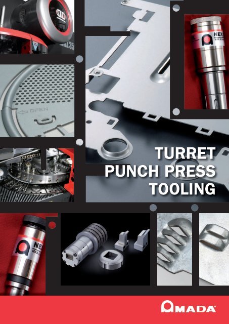
<strong>TURRET</strong><br />
<strong>PUNCH</strong> <strong>PRESS</strong><br />
<strong>TOOLING</strong>
<strong>TURRET</strong><br />
<strong>PUNCH</strong> <strong>PRESS</strong><br />
<strong>TOOLING</strong>
AMADA<br />
<strong>PUNCH</strong>ING TOOLS<br />
CONTENTS<br />
• Standard shape • • • • • • • • • PAGES<br />
A( 1 / 2”), B(1 1 / 4”) NEX spring & PV die performance guide 1 - 2<br />
A ( 1 / 2’’) Tip type round / original (Ø 0.8 ~ Ø 1.5mm) 2<br />
A ( 1 / 2’’) Round (Ø 1.51 ~ Ø 3.2mm) 3 - 4<br />
A ( 1 / 2’’) Round (Ø 3.21 ~ Ø 12.7mm) 5 - 6<br />
A ( 1 / 2’’) Shape inscribed 12.7mm 7 - 8<br />
B (1 1 / 4’’) Round Air-Blow : Ø 12.71 ~ Ø 30.0mm / Original : Ø 12.71 ~ Ø 31.7mm 9 - 10<br />
B (1 1 / 4’’) Shape Air-Blow : inscribed Ø 30.0mm / Original : Ø 12.71 ~ Ø 31.7mm 11 - 12<br />
C (2’’), D (3 1 / 2’’) & E (4 1 / 4’’) Alpha guide 13 - 14<br />
C (2’’), D (3 1 / 2’’) Large station guide list 15<br />
St C (2’’), D (3 1 / 2’’), E (4 1 / 2’’) Sheet saver guide, stripper & die 16<br />
E (4 1 / 2’’) Large Station Guide List 16<br />
C (2’’) Round & shape 17 - 18<br />
D (3 1 / 2’’) Round & shape solid type & tip type 19 - 20<br />
E (4 1 / 2’’) Round & shape solid type & tip type 21 - 22<br />
• Forming special purpose tool • • • • • • • • • • PAGES<br />
B (1 1 / 4’’) Upform burring 23 - 24<br />
B (1 1 / 4’’) Downform burring 25 - 26<br />
B (1 1 / 4’’) BK burring tool 27<br />
B (1 1 / 4’’) FP (Flat Positioning) tool 28<br />
A ( 1 / 2’’) Upform center punch tool 29<br />
A ( 1 / 2’’) Downform center punch & High speed marking tool 29<br />
C (2’’), D (3 1 / 2’’) & E (4 1 / 2’’) Slotting tool III 30<br />
C (2’’) Cartridge-type tapping tool III 31 - 32<br />
A ( 1 / 2’’) Contouring tool 33 - 34<br />
B (1 1 / 4’’) Deburring tool 35 - 36<br />
A ( 1 / 2’’) Both side chamfered tool for tapping tool 35 - 36<br />
C (2’’) Inch bend tool 37<br />
D (3 1 / 2’’), E(4 1 / 2’’) Work chute tool 38<br />
A ( 1 / 2’’) Downform countersink tool set 39<br />
B (1 1 / 4’’) Burring tool set 39<br />
Web site<br />
www.amada.fr
• Options et accessoires et machines • • • • • • • • • PAGES<br />
QS stripper A ( 1 / 2’’) and B (1 1 / 4’’) 40<br />
Roller die and flat die A ( 1 / 2’’) to E (4 1 / 2’’) 40<br />
Brush die A ( 1 / 2’’) to E (4 1 / 2’’) 40<br />
Conversion sleeve B (1 1 / 4’’) -> A ( 1 / 2’’) 40<br />
Felt (FS oil) A ( 1 / 2’’) to E (4 1 / 2’’) 40<br />
Belleville spring B (1 1 / 4’’) 40<br />
Shim keepers A ( 1 / 4’’) and B (1 1 / 2’’) 41<br />
Shims A ( 1 / 2’’) to E (4 1 / 2’’) 41<br />
Assembly / Desassembly device A ( 1 / 2’’) to E (4 1 / 4’’) 41<br />
Slug ejectors A ( 1 / 2’’) to E (4 1 / 2’’) 41<br />
Torques screw A ( 1 / 2’’) to E (4 1 / 2’’) 41<br />
Slug ejector replacement kit 42<br />
Automatic tool grinding machine TOGU EU 43 - 44<br />
QS pliers 44<br />
Air-blow system V-EX 45<br />
• Tool selection guide • • • • • • • • • PAGES<br />
Special shape tooling (Semi-standard tooling) 46<br />
Punching tool steel type & features 47<br />
Cautions and instructions about tooling 47<br />
Shape, size and key angle 48<br />
Table of recommended die clearance 48<br />
Punching force calculation method 48<br />
Minimum punchable hole diameter 48<br />
• Large station guide parts list • • • • • • • • • PAGES<br />
C (2’’) Alpha guide assy 49 - 50<br />
D (3 1 / 2’’) Alpha guide assy 51 - 52<br />
E (4 1 / 2’’) Alpha guide assy 53 - 54<br />
C (2’’) Alpha sheet saver guide assy 55 - 56<br />
D (3 1 / 2’’) Alpha blade guide assy 57 - 58<br />
E (4 1 / 2’’) Alpha blade guide assy 59 - 60<br />
C (2’’) Thick Turret Z style guide parts list 61 - 62<br />
D (3 1 / 2’’) Thick Turret Z style guide parts list 63 - 64<br />
E (4 1 / 2’’) Thick Turret Z style guide parts list 65 - 66<br />
• Applicable machine models • • • • • • • • •<br />
EM, EML, AC, APELIO, LIBRA, COMA, PEGA(H), OCTO(H), VELAII(H), LYRA, ARIES(H), SPINGAR, EUROPE AND ARCADE<br />
Use <strong>Ama</strong>da’s genuine tool on <strong>Ama</strong>da machines.<br />
<strong>Ama</strong>da is unable to guarantee maintenance for any trouble resulting from use of other tool.<br />
AMADA outillage<br />
ZI BP 35 Tél. : +33 (0)2 32 80 81 00<br />
76720 Auffay Fax : +33 (0)2 35 32 76 46<br />
France<br />
info@amada-outillage.fr
Punch body replacement and height adjustement become so easy by new spring assy mechanisms.<br />
Tooling costs is dramatically reduced by spring assy + guide combination and by the the grind<br />
length increase.<br />
--- Tooling recommanded for EM series of machines ---<br />
NEX Spring Assy<br />
For long tooling A ( 1 /2’’) and B (1 1 /4’’)<br />
Maxthickness 6.0mm<br />
Mild steel - aluminum max 6.0mm<br />
Stainless steel max 3.0mm<br />
Nex spring assembly can be<br />
use for both Air-Blow and<br />
original style punch body<br />
Grinding amount increased<br />
to a maximum of 5.0 mm<br />
maximum of 5.0 mm. This means that a punch thatmay have<br />
reached its grinding limit of a conventionnal standard type<br />
can now be reground and reused.peut désormais être encore<br />
affuté et utilisé.<br />
Maintenance time reduce to 1/3<br />
Height adjustment and punch body change can be performed<br />
simply by loosening the lock bolt and turning the punch body.<br />
Height adjustment<br />
Height adjustment<br />
Grind margin<br />
Closed guide<br />
NEX spring assembly<br />
Lock bolt<br />
A (1/2’’) and B (11/4’’)<br />
both punch assembly length 208mm<br />
Conventional punch bodies also utilizable<br />
NEX spring units and closed guides are common to all punches<br />
of the same size. Conventional punch bodies can be directly<br />
used as well.<br />
One-piece spring pack keeps<br />
the constant height<br />
The punch head and spring unit are combined into one structure<br />
to keep the overall punch assembly height unchanged despite<br />
height adjustment.<br />
Closed guide<br />
NEX spring assembly<br />
Optimum benefits air-blow<br />
tooling displayed<br />
The air-blow system supplies the air-blow tooling with air and oil mist<br />
to prevent deposition and slug pulling and to facilitate maintenance.<br />
Benefit of air-blow tooling<br />
Prevention of entry<br />
of foreign body<br />
Reduction of<br />
slug pulling<br />
Reduction of<br />
strip failures<br />
Droop<br />
Burr<br />
16<br />
Reduction of fine<br />
needle pulling<br />
Retain hole<br />
accuracy<br />
Top dead<br />
center<br />
Contact of guide<br />
with material<br />
Punching<br />
Rise of tooling
Power Vacuum Die: standard die for EM & AC for A ( 1 /2’’) et B (1 1 /4’’)<br />
Vacuum suction unit by air jet flowing downwards in the die preventing slug-pulling<br />
Vacuum die<br />
Die<br />
Power vacuum die<br />
Air<br />
Die holder<br />
Ejector pipe<br />
Vacuum<br />
die holder<br />
Air<br />
B (1 1 /4’’) A ( 1 /2’’)<br />
Tooling size<br />
Specification<br />
Vacuum unit Turret size Air flow line<br />
A ( 1 / 2’’)<br />
Power vacuum die<br />
(PV)<br />
Power vacuum<br />
(PV)<br />
Die has a small pin holes<br />
aiming toward downward , and<br />
this creates maximum vacuum<br />
effect.<br />
Same diameter turret<br />
Air<br />
B(1 1 / 4’’)<br />
Air jet vacuum<br />
(AJV)<br />
Slug vacuum system by strong<br />
jet air projected toward<br />
downward under the die.<br />
Z turret<br />
Air<br />
* Power vacuum die cannot be applied on PKK die and back tapered die, because of less effectiveness of slug-pulling prevention.<br />
* Z turret uses AJV system, air projected position is different from power vacuum system. (See upper drawing)<br />
* Power vacuum system works A(½”) and B(1¼”) on the same diameter turret. (except auto index station)<br />
A ( 1 / 2’’) Size ROUND (Ø 0.8 ~ Ø 1.5mm) Tip type Original style<br />
• Tooling selection and code<br />
Description<br />
Punch<br />
Material<br />
Grade<br />
Die<br />
Material<br />
Code N°<br />
Set assy<br />
SKH<br />
Original<br />
SKD<br />
Punch assy<br />
SKH<br />
Punch tip<br />
SKH<br />
Set assy<br />
Punch assy<br />
209.5 (Punch height 206.5)<br />
PV SKH<br />
Die<br />
Original<br />
SKH<br />
SKD<br />
• Component parts list<br />
N° Description Code N°<br />
1<br />
2<br />
Double punch head<br />
Stripping spring<br />
3<br />
Punch driver<br />
4<br />
Retainer collar<br />
5<br />
O-ring<br />
Punch tip<br />
6<br />
Closed guide with bush & O-ring<br />
Ø 25.91<br />
7<br />
Lock screw (M10x10)<br />
8<br />
Straight pin<br />
Die<br />
30<br />
PV Die<br />
9<br />
10<br />
Punch body<br />
Urethane tube (10pcs.)<br />
Ø 25.4<br />
Ø 25.4<br />
11<br />
Urethane tube (10pcs.)<br />
2
A ( 1 / 2’’) Size ROUND (Ø 1.51 ~ Ø 3.2mm)<br />
NEX Air-Blow<br />
NEX Original Style<br />
Set assy<br />
Punch assy<br />
208 (Punch height 206.5 / Punch body 207)<br />
NEX spring assy<br />
Closed<br />
guide<br />
Punch<br />
body<br />
Open<br />
guide<br />
Set assy<br />
Punch assy<br />
208 (Punch height 206.5 / Punch body 207)<br />
NEX spring assy<br />
Closed<br />
guide<br />
Punch<br />
body<br />
Open<br />
guide<br />
Ø 25.91<br />
Ø 25.91<br />
Die<br />
30<br />
Original<br />
Die<br />
PV Die<br />
Die<br />
30<br />
Original<br />
Die<br />
PV Die<br />
Ø 25.4<br />
Ø 25.4<br />
Ø 25.4<br />
Ø 25.4<br />
* Closed guide is recommended for EM machine.<br />
Original style<br />
Set assy<br />
Punch assy<br />
208 (Punch height 206.5 / Punch body 207)<br />
Closed<br />
guide<br />
Punch<br />
body<br />
Open<br />
guide<br />
O-ring type for retainer<br />
Closed guide<br />
Install O-ring<br />
on to guide<br />
Open guide<br />
Install O-ring<br />
on to retainer<br />
Ø 25.91<br />
Die<br />
30<br />
Original<br />
Die<br />
PV Die<br />
Ø 25.4<br />
Ø 25.4<br />
3
A ( 1 / 2’’) Size ROUND<br />
• Tooling selection and code<br />
Description<br />
Punch<br />
Material Grade Material Open guide<br />
APH<br />
APV<br />
Original<br />
Die NEX Air-Blow NEX Original style Original style<br />
HSS<br />
HSS<br />
HWS<br />
Closed<br />
guide<br />
Open guide<br />
Closed<br />
guide<br />
Open guide<br />
Closed<br />
guide<br />
Set<br />
assy<br />
HSS<br />
+<br />
TiCN<br />
APV<br />
Original<br />
HSS<br />
HSS<br />
HWS<br />
HSS<br />
APV<br />
Original<br />
HSS<br />
HSS<br />
HWS<br />
Punch<br />
assy<br />
APH<br />
HSS +TiCN<br />
HSS<br />
APH<br />
Punch<br />
body<br />
HSS +TiCN<br />
HSS<br />
Original<br />
HSS<br />
HWS<br />
APV<br />
HSS<br />
Die<br />
ARX<br />
HSS<br />
HWS<br />
PKK die<br />
Ø 2.0mm or more<br />
HSS<br />
HWS<br />
26142K<br />
21142K<br />
26142K 26142K 26142K 26142K 26142K<br />
21142K 21142K 21142K 21142K 21142K<br />
• Component parts list<br />
Fig. N° Description Code N°<br />
1 NEX spring assy<br />
PKK die*<br />
2<br />
3<br />
4<br />
5<br />
6<br />
O-ring<br />
Urethane tube (10pcs.)<br />
Closed guide (AB)<br />
Open guide (AB)<br />
QM stripper plate (AB)<br />
Closed guide<br />
Open guide<br />
5 6<br />
7<br />
8<br />
9<br />
8 9<br />
10<br />
11<br />
12<br />
13<br />
14<br />
Open guide (AB) & QM stripper plate (AB)<br />
Closed guide (Original style)<br />
Open guide (Original style)<br />
QM stripper plate (Original style)<br />
Open guide (Original) & QM stripper plate (Original)<br />
Punch head<br />
Stripping spring<br />
Retainer collar<br />
Spring cover<br />
QS pliers<br />
* Retainer slug profile<br />
4
A ( 1 / 2’’) Size ROUND (Ø 3.21 ~ Ø 12.7mm)<br />
NEX Air-Blow<br />
NEX Original Style<br />
Set assy<br />
Punch assy<br />
208 (Punch height 207.5 / Punch body 207)<br />
NEX spring assy<br />
Closed<br />
guide<br />
Punch<br />
body<br />
Open<br />
guide<br />
Set assy<br />
Punch assy<br />
208 (Punch height 207.5 / Punch body 207)<br />
NEX spring assy<br />
Closed<br />
guide<br />
Punch<br />
body<br />
Open<br />
guide<br />
Ø 25.91<br />
Ø 25.91<br />
Die<br />
30<br />
Original<br />
Die<br />
PV Die<br />
Die<br />
30<br />
Original<br />
Die<br />
PV Die<br />
Ø 25.4<br />
Ø 25.4<br />
Ø 25.4<br />
Ø 25.4<br />
* Closed guide is recommended for EM machine.<br />
* Punch bigger than 6.0mm diameter has a center hole.<br />
* Punch bigger than 6.0mm diameter has a slug ejector.<br />
Original style<br />
O-ring type for retainer<br />
Closed guide<br />
Open guide<br />
Set assy<br />
Punch assy<br />
209.5 (Punch height 207.5 / Punch body 207)<br />
Closed<br />
guide<br />
Punch<br />
body<br />
Open<br />
guide<br />
Install O-ring<br />
on to guide<br />
Install O-ring<br />
on to retainer<br />
Ø 25.91<br />
Die<br />
30<br />
Original<br />
Die<br />
PV Die<br />
Ø 25.4<br />
Ø 25.4<br />
* Punch bigger than 6.0mm diameter has a slug ejector.<br />
5
A ( 1 / 2’’) Size ROUND<br />
• Tooling selection and code<br />
Description<br />
Set<br />
assy<br />
Punch<br />
assy<br />
Punch<br />
body<br />
Die<br />
Poinçon<br />
Material Grade Material Open guide<br />
APH<br />
HSS<br />
+<br />
TiCN<br />
HSS<br />
APH<br />
HSS +TiCN<br />
HSS<br />
APH<br />
HSS +TiCN<br />
HSS<br />
APV<br />
Original<br />
APV<br />
Original<br />
APV<br />
Original<br />
Original<br />
APV<br />
ARX<br />
PKK die<br />
Ø 2.0mm or more<br />
Matrice NEX Air-Blow NEX Original style Original style<br />
HSS<br />
HSS<br />
HWS<br />
HSS<br />
HSS<br />
HWS<br />
HSS<br />
HSS<br />
HWS<br />
HSS<br />
HWS<br />
HSS<br />
HSS<br />
HWS<br />
HSS<br />
HWS<br />
26142K<br />
21142K<br />
Closed<br />
guide<br />
Open guide<br />
Closed<br />
guide<br />
Open guide<br />
Closed<br />
guide<br />
26142K 26142K 26142K 26142K 26142K<br />
21142K 21142K 21142K 21142K 21142K<br />
• Component parts list<br />
Fig N° Description Code N°<br />
1 NEX spring assy<br />
Closed guide<br />
2 O-ring<br />
Open guide<br />
PKK die*<br />
3<br />
4<br />
5<br />
6<br />
5 6<br />
7<br />
8<br />
9<br />
8 9<br />
10<br />
11<br />
12<br />
13<br />
14<br />
Urethane tube (10pcs.)<br />
Closed guide (AB)<br />
Open guide (AB)<br />
QM stripper plate (AB)<br />
Open guide (AB) & QM stripper plate (AB)<br />
Closed guide (Original style)<br />
Open guide (Original style)<br />
QM stripper plate (Original style)<br />
Open guide (Original) & QM stripper plate (Original)<br />
Punch head<br />
Stripping spring<br />
Retainer collar<br />
Spring cover<br />
QS pliers<br />
* Retainer slug profile<br />
6
A ( 1 / 2’’) Size SHAPE Inscribed 12.7mm<br />
NEX Air-Blow<br />
NEX Original Style<br />
Set assy<br />
Punch assy<br />
208 (Punch height 207.5 / Punch body 207)<br />
NEX spring assy<br />
Closed<br />
guide<br />
Punch<br />
body<br />
Open<br />
guide<br />
Set assy<br />
Punch assy<br />
208 (Punch height 207.5 / Punch body 207)<br />
NEX spring assy<br />
Closed<br />
guide<br />
Punch<br />
body<br />
Open<br />
guide<br />
Ø 25.91<br />
Ø 25.91<br />
Die<br />
30<br />
Original<br />
Die<br />
PV Die<br />
Die<br />
30<br />
Original<br />
Die<br />
PV Die<br />
Ø 25.4<br />
Ø 25.4<br />
Ø 25.4<br />
Ø 25.4<br />
* Closed guide is recommended for EM machine.<br />
* Punch bigger than 6.0mm diameter has a center hole.<br />
* Punch bigger than 6.0mm diameter has a slug ejector.<br />
Original style<br />
O-ring type for retainer<br />
Closed guide<br />
Open guide<br />
Set assy<br />
Punch assy<br />
209.5 (Punch height 207.5 / Punch body 207)<br />
Closed<br />
guide<br />
Punch<br />
body<br />
Open<br />
guide<br />
Install O-ring<br />
on to guide<br />
Install O-ring<br />
on to retainer<br />
Ø 25.91<br />
Die<br />
30<br />
Original<br />
Die<br />
PV Die<br />
Ø 25.4<br />
Ø 25.4<br />
* Punch bigger than 6.0mm diameter has a slug ejector.<br />
7
A ( 1 / 2’’) Size SHAPE<br />
• Tooling selection and code<br />
Poinçon Matrice NEX Air-Blow NEX Original style Original style<br />
Description<br />
Material Grade Material Open guide<br />
Closed<br />
guide<br />
Open guide<br />
Closed<br />
guide<br />
Open guide<br />
Closed<br />
guide<br />
APV HSS<br />
APH<br />
Original<br />
HSS<br />
HWS<br />
Set<br />
assy<br />
Punch<br />
assy<br />
Punch<br />
body<br />
Die<br />
HSS<br />
+<br />
TiCN<br />
SKH<br />
APH<br />
HSS +TiCN<br />
HSS<br />
APH<br />
HSS +TiCN<br />
HSS<br />
APV<br />
Original<br />
APV<br />
Original<br />
Original<br />
APV<br />
ARX<br />
PKK die<br />
Ø 2.0mm or more<br />
HSS<br />
HSS<br />
HWS<br />
HSS<br />
HSS<br />
HWS<br />
HSS<br />
HWS<br />
HSS<br />
HSS<br />
HWS<br />
HSS<br />
HWS<br />
27142K<br />
22142K<br />
27142K 27142K 27142K 27142K 27142K<br />
22142K 22142K 22142K 22142K 22142K<br />
• Component parts list<br />
Fig N° Description Code N° PKK die*<br />
1 NEX spring assy<br />
2<br />
3<br />
4<br />
5<br />
6<br />
O-ring<br />
Urethane tube (10pcs.)<br />
Closed guide (AB)<br />
Open guide (AB)<br />
QM stripper plate (AB)<br />
Closed guide<br />
Open guide<br />
5 6 Open guide (AB) & QM stripper plate (AB)<br />
7<br />
8<br />
Closed guide (Original style)<br />
Open guide (Original style)<br />
9 QM stripper plate (Original style)<br />
* Retainer slug profile<br />
8 9 Open guide (Original) & QM stripper plate (Original)<br />
10<br />
11<br />
12<br />
13<br />
14<br />
Punch head<br />
Stripping spring<br />
Retainer collar<br />
Spring cover<br />
QS pliers<br />
Additional cost<br />
* Aditional keyway (Standard keyway : 0° ,90°)<br />
* Roof top 2° for A/B/C/D Station (E Station Standard)<br />
* Narrow type (Stubby punch): Shape under 2.4 mm for A & B St, under 4 mm for C, D & E St.<br />
8
B (1 1 / 4’’) Size<br />
ROUND<br />
Air-Blow : Ø 12.71 ~ Ø 30.0mm<br />
Original style : Ø 12.71 ~ Ø 31.7mm<br />
NEX Air-Blow<br />
NEX Original Style<br />
Set assy<br />
Punch assy<br />
208 (Punch height 207.5 / Punch body 207)<br />
NEX spring assy<br />
Closed<br />
guide<br />
Punch<br />
body<br />
Open<br />
guide<br />
Set assy<br />
Punch assy<br />
208 (Punch height 207.5 / Punch body 207)<br />
NEX spring assy<br />
Closed<br />
guide<br />
Punch<br />
body<br />
Open<br />
guide<br />
Ø 47.83<br />
Ø 47.83<br />
Die<br />
30<br />
Original<br />
Die<br />
PV Die<br />
Die<br />
30<br />
Original<br />
Die<br />
PV Die<br />
Ø 47.62<br />
Ø 47.62<br />
Ø 47.62<br />
Ø 47.62<br />
* Closed guide is recommended for EM machine.<br />
* Punch bigger than 6.0mm diameter has a center hole.<br />
* Punch bigger than 6.0mm diameter has a slug ejector.<br />
Original style<br />
Set assy<br />
Punch assy<br />
209.5 (Punch height 207.5 / Punch body 207)<br />
Punch<br />
body<br />
Open<br />
guide<br />
Closed<br />
guide<br />
Die<br />
30<br />
Original<br />
Die<br />
PV Die<br />
Ø 47.62<br />
Ø 47.62<br />
* Punch bigger than 6.0mm diameter has a slug ejector.<br />
9
B (1 1 / 4’’) Size ROUND<br />
• Tooling selection and code<br />
Description<br />
Set<br />
assy<br />
Punch<br />
assy<br />
Punch<br />
body<br />
Die<br />
Poinçon Matrice NEX Air-Blow NEX Original style Original style<br />
Material Grade Material Open guide<br />
Closed<br />
guide<br />
Open guide<br />
Closed<br />
guide<br />
Open guide<br />
Closed<br />
guide<br />
APV HSS<br />
APH<br />
Original<br />
HSS<br />
HWS<br />
HSS<br />
+<br />
TiCN<br />
HSS<br />
APH<br />
HSS +TiCN<br />
SKH<br />
APH<br />
HSS +TiCN<br />
HSS<br />
APV<br />
Original<br />
APV<br />
Original<br />
Original<br />
APV<br />
ARX<br />
PKK die<br />
Ø 2.0mm or more<br />
HSS<br />
HSS<br />
HWS<br />
HSS<br />
HSS<br />
HWS<br />
HSS<br />
HWS<br />
HSS<br />
HSS<br />
HWS<br />
HSS<br />
HWS<br />
26144K<br />
21144K<br />
26144K 26144K 26144K 26144K 26144K<br />
21144K 21144K 21144K 21144K 21144K<br />
• Component parts list<br />
Fig N° Description Code N° PKK die*<br />
1<br />
2<br />
3<br />
4<br />
5<br />
6<br />
5 6<br />
7<br />
8<br />
9<br />
8 9<br />
10<br />
11<br />
12<br />
13<br />
14<br />
NEX spring assy<br />
O-ring<br />
Urethane tube (10pcs.)<br />
Closed guide (AB)<br />
Open guide (AB)<br />
QM stripper plate (AB)<br />
Open guide (AB) & QM stripper plate (AB)<br />
Closed guide (Original style)<br />
Open guide (Original style)<br />
QM stripper plate (Original style)<br />
Open guide (Original) & QM stripper plate (Original)<br />
Punch head<br />
Stripping spring<br />
Retainer collar<br />
Spring cover<br />
QS pliers<br />
* Retainer slug profile<br />
10
B (1 1 / 4’’) Size<br />
SHAPE<br />
Air-Blow : inscribed Ø 30.0mm (rectangle less than 10x30mm)<br />
Original style : Ø 12.71 ~ Ø 31.7mm<br />
NEX Air-Blow<br />
NEX Original Style<br />
Set assy<br />
Punch assy<br />
208 (Punch height 207.5 / Punch body 207)<br />
NEX spring assy<br />
Closed<br />
guide<br />
Punch<br />
body<br />
Open<br />
guide<br />
Set assy<br />
Punch assy<br />
208 (Punch height 207.5 / Punch body 207)<br />
NEX spring assy<br />
Closed<br />
guide<br />
Punch<br />
body<br />
Open<br />
guide<br />
Ø 47.83<br />
Ø 47.83<br />
Die<br />
30<br />
Original<br />
Die<br />
PV Die<br />
Die<br />
30<br />
Original<br />
Die<br />
PV Die<br />
Ø 47.62<br />
Ø 47.62<br />
Ø 47.62<br />
Ø 47.62<br />
* Le guide fermé est recommandé pour la machine EM.<br />
* Un poinçon supérieur à Ø 6 mm a un perçage central.<br />
* Punch bigger than 6.0mm diameter has a slug ejector.<br />
Original style<br />
Set assy<br />
Punch assy<br />
209.5 (Punch height 207.5 / Punch body 207)<br />
Punch<br />
body<br />
Open<br />
guide<br />
Closed<br />
guide<br />
Die<br />
30<br />
Original<br />
Die<br />
PV Die<br />
Ø 47.62<br />
Ø 47.62<br />
* Punch bigger than 6.0mm diameter has a slug ejector.<br />
11
B (1 1 / 4’’) Size SHAPE<br />
• Tooling selection and code<br />
Description<br />
Set<br />
assy<br />
Punch<br />
assy<br />
Punch<br />
body<br />
Die<br />
Punch<br />
Die NEX Air-Blow NEX Original style Original style<br />
Material Grade Material Open guide<br />
APV HSS<br />
APH<br />
Original<br />
HSS<br />
HWS<br />
HSS<br />
+<br />
TiCN<br />
HSS<br />
APH<br />
HSS +TiCN<br />
HSS<br />
APH<br />
HSS +TiCN<br />
HSS<br />
APV<br />
Original<br />
APV<br />
Original<br />
Original<br />
APV<br />
ARX<br />
PKK die<br />
Ø 2.0mm or more<br />
HSS<br />
HSS<br />
HWS<br />
HSS<br />
HSS<br />
HWS<br />
HSS<br />
HWS<br />
HSS<br />
HSS<br />
HWS<br />
HSS<br />
HWS<br />
27144K<br />
22144K<br />
Closed<br />
guide<br />
Open guide<br />
Closed<br />
guide<br />
Open guide<br />
Closed<br />
guide<br />
27144K 27144K 27144K 27144K 27144K<br />
22144K 22144K 22144K 22144K 22144K<br />
• Component parts list<br />
Fig N° Description Code N°<br />
1<br />
2<br />
3<br />
4<br />
5<br />
6<br />
5 6<br />
NEX spring assy<br />
O-ring<br />
Urethane tube (10pcs.)<br />
Closed guide (AB)<br />
Open guide (AB)<br />
QM stripper plate (AB)<br />
Open guide (AB) & QM stripper plate (AB)<br />
7<br />
8<br />
9<br />
8 9<br />
Closed guide (Original style)<br />
Open guide (Original style)<br />
QM stripper plate (Original style)<br />
Open guide (Original) & QM stripper plate (Original)<br />
10<br />
11<br />
12<br />
13<br />
14<br />
Punch head<br />
Stripping spring<br />
Retainer collar<br />
Spring cover<br />
QS pliers<br />
PKK die*<br />
* Retainer slug profile<br />
Additional Option cost Les poinçons rayonnés et de forme spéciales font l’ojet d’un supplément.<br />
* Aditional keyway (Standard keyway : 0° ,90°)<br />
* Roof top 2° for A/B/C/D Station (E Station Standard)<br />
* Narrow type (Stubby punch): Shape under 2.4 mm for A & B St, under 4 mm for C, D & E St.<br />
12
C (2’’), D (3 1 / 2’’), E (4 1 / 2’’)<br />
Large station Alpha guide series<br />
Realize the time reduction for tooling maintenance!<br />
The tooling cost of large-size punches is sharply reduced.<br />
The punch tip can be more easily changed and adjusted.<br />
Air-blow effect is substantially improved.<br />
___ Tooling recommended for EM machines series ___<br />
(Alpha) guides<br />
(Alpha) blade guides<br />
For long tooling D (3 1 / 2’’), E (4 1 / 2’’)<br />
(Alpha) guides<br />
For long tooling C (2’’)<br />
C (2’’)<br />
guide<br />
D (3 1 /2’’) guide E (4 1 /2’’) blade guide<br />
Tooling cost reduction<br />
guide and blade guide have a dual structure, the punch driver can slide internally and make easy height adjustment without<br />
shim. Therefore maximum tool grinding value become 2.5 times longer to maximum 5mm.<br />
Combination use of blade guide and blade punch reduce the tooling cost for rectangle and obround shape punch body.<br />
One touch punch height adjustment<br />
Easy adjustment by pushing the adjustment button and<br />
rotating the punch head. No additional hand tools are required.<br />
Easy stripper plate replacement<br />
Stripper plates can be easily removed without the need for hand tools.<br />
Stripper plates can be easily removed without the need for hand tools.<br />
Note : Torques wrench is needed for the removal of Z style stripper from<br />
guide adapter..<br />
(10mm)<br />
A<br />
B<br />
Minimum<br />
35mm<br />
Work clamp<br />
• sheet saver type clamp dead zone<br />
13
guide combination<br />
guide blade guide<br />
Punch body and punch tip can be loaded<br />
Specified guide for<br />
blade punch<br />
Air-blow punch<br />
Original style punch<br />
blade punch<br />
M14 bolt<br />
M12 bolt<br />
+<br />
Collar<br />
B<br />
A<br />
Punch body<br />
Punch holder<br />
Punch body<br />
Punch holder<br />
Punch type<br />
blade punch<br />
Tool size D (3 1 / 2’’) E (4 1 / 2’’)<br />
A<br />
1.5~18mm<br />
B (max) 85mm 110mm<br />
Max diagonal<br />
Air-Blow Original style Air-Blow Original style<br />
Ø 85.6mm Ø 88.9mm Ø 110.5mm Ø 114.0mm<br />
Punch tip<br />
Punch tip<br />
* Max dimension is A size size diagonal.<br />
* blade punch is deferent from the tip type punch for large size.<br />
blade punch is only loaded on blade guide.<br />
* Jig is required for punch tip regrinding on TOGU III.<br />
guide adapter sheet saver stripper<br />
(Air-Blow or Original style)<br />
solid stripper<br />
(Air-blow or Original style)<br />
1 side escape<br />
2 sides escape<br />
Z style air-blow<br />
stripper<br />
Original style<br />
stripper<br />
Current stripper plate can be used<br />
Material utilization ratio increases<br />
Easy replacement of stripper.<br />
Can be used for cluster punch<br />
14
Thick Turret C (2’’) Size Large station guides<br />
N°1 N°2 N°3<br />
guide Air-blow guide Original style guide<br />
• Component parts list<br />
Type<br />
Description<br />
N°<br />
Alpha guide Alpha guide assy 1<br />
Air-blow guide Air-blow guide assy 2<br />
Original style guide Original style guide assy 3<br />
Code<br />
Thick Turret D (3 1 / 2’’) Size Large station guides<br />
• List of componants<br />
N°1 N°2<br />
guide<br />
guide adapter<br />
assy<br />
guide adapter<br />
Z style Air-blow<br />
standard stripper<br />
(not included)<br />
N°3 N°4<br />
blade<br />
guide<br />
guide adapter<br />
assy<br />
guide adapter<br />
Z style Air-blow<br />
standard stripper<br />
(not included)<br />
Air-blow<br />
guide,<br />
Original style<br />
guide<br />
N°5 N°6<br />
Air-Blow guide<br />
Original style<br />
guide<br />
• Component parts list<br />
Type<br />
Description<br />
N°<br />
Alpha guide assy without adapter 1<br />
Alpha guide Alpha guide assy with adapter 2<br />
Alpha guide adapter<br />
Alpha blade guide<br />
Alpha blade guide assy without adapter 3<br />
Alpha blade guide assy with adapter 4<br />
Air-Blow guide Air-blow guide assy 5<br />
Original syle guide Original style guide assy 6<br />
Code<br />
15
C (2’’), D (3 1 / 2’’), E (4 1 / 2’’) Size Sheet saver guide, stripper & die<br />
• Tooling selection and code<br />
Work clamp<br />
Tool size<br />
C (2’’)<br />
D (3 1 / 2’’)<br />
E (4 1 / 2’’)<br />
Description<br />
Code<br />
Alpha sheet saver guide assy<br />
90744E<br />
Original style sheet saver stripper plate<br />
900205EU<br />
Air-blow sheet saver stripper plate<br />
900275EU<br />
Sheet saver die 220060<br />
Alpha blade guide assy<br />
90713E<br />
Original style sheet saver stripper plate 900210<br />
Air-blow sheet saver stripper plate 900280<br />
Sheet saver die 220080<br />
Alpha blade guide assy<br />
90714E<br />
Original style sheet saver stripper plate 900310<br />
Air-blow sheet saver stripper plate 900290<br />
Sheet saver die 220090<br />
Thick Turret E (4 1 / 2’’) Size Large station guides<br />
• Tooling selection and code<br />
N°1 N°2<br />
guide<br />
guide adapter<br />
assy<br />
guide adapter<br />
Z style Air-blow<br />
standard stripper<br />
(not included)<br />
N°3 N°4<br />
blade<br />
guide<br />
Air-blow<br />
guide,<br />
Original style<br />
guide<br />
N°5 N°6<br />
Air-Blow guide<br />
guide adapter<br />
assy<br />
guide adapter<br />
Z style Air-blow<br />
standard stripper<br />
(not included)<br />
Original style<br />
guide<br />
• Component parts list<br />
Type<br />
Description<br />
N°<br />
Code<br />
Alpha guide assy without adapter 1<br />
Alpha guide Alpha guide assy with adapter 2<br />
Alpha guide adapter<br />
Alpha blade guide<br />
Alpha blade guide assy without adapter 3<br />
Alpha blade guide assy with adapter 4<br />
Air-Blow guide Air-blow guide assy 5<br />
Original syle guide Original style guide assy 6<br />
16
Thick Turret C (2’’) Size<br />
Punch-Die<br />
Shape<br />
Tool size<br />
Air-Blow<br />
Round<br />
Original style<br />
Max Size<br />
Ø 30.01 ~ Ø 47 mm<br />
Ø 31.71 ~ Ø 50.8 mm<br />
Ø 51 Ø 51<br />
Structure<br />
Die<br />
Set assy<br />
Punch assy<br />
Punch body<br />
96<br />
Set assy<br />
Punch assy<br />
Punch body<br />
30<br />
96<br />
Die<br />
30<br />
Ø 88. 89 Ø 88. 89<br />
• Tooling selection and code<br />
Description<br />
Punch<br />
Die Round Shape<br />
Material Grade<br />
Material Air-Blow Original Air-Blow Original<br />
APH<br />
Original<br />
HSS<br />
Set assy<br />
HSS +TiCN<br />
Original<br />
HSS<br />
HSS<br />
Original<br />
HSS<br />
Punch<br />
assy<br />
APH<br />
HSS +TiCN<br />
HSS<br />
APH<br />
Punch<br />
body<br />
HSS +TiCN<br />
HSS<br />
41F060<br />
42F060<br />
Stripper<br />
plate<br />
Z style air-blow stripper plate<br />
Sheet saver<br />
52F160 520160<br />
Original<br />
HSS<br />
HWS<br />
Die<br />
Sheet saver die<br />
HSS<br />
HWS<br />
22506Z 22506Z<br />
220060 220060<br />
HSS<br />
ARX<br />
HWS<br />
PKK die<br />
Round Ø 2.0mm or more<br />
Shape 2.0mm width or more<br />
HSS<br />
HWS<br />
21546K 21546K 22546K 22546K<br />
21146K 21146K 22146K 22146K<br />
17
C (2’’) Size Punch-Die<br />
Shape<br />
Air-Blow<br />
Original<br />
Inscribed 47mm diagonal<br />
Rectangle less 10mm X less 50mm<br />
Inscribed 50.8mm<br />
Ø 51 Ø 51<br />
Die<br />
30<br />
Die<br />
30<br />
Set assy<br />
Punch assy<br />
Poinçon<br />
96<br />
Set assy<br />
Punch assy<br />
Punch body<br />
96<br />
Ø 88. 89 Ø 88. 89<br />
Sheet saver stripper plate<br />
Sheet saver die<br />
• Notes<br />
* AdditionnaI keyway<br />
* Roof top 2° for A/B/C/D Station (E Station Standard)<br />
* Narrow type (Stubby punch): Shape under 2.4 mm for A & B St, under 4mm for C, D & E St<br />
18
Thick Turret D (3 1 / 2’’) Size<br />
Large station Punch-Die<br />
• Solid type punch<br />
Type<br />
Round<br />
Shape<br />
Tool type<br />
Air-Blow<br />
Original style<br />
Air-Blow<br />
Original style<br />
Max size<br />
Ø 47.01 ~ Ø 85.6 mm Ø 50.81 ~ Ø 88.9 mm Inscribed 85.6 mm Inscribed 88.9 mm<br />
Ø 89. 41 Ø 89. 41 Ø 89. 41 Ø 89. 41<br />
Structure<br />
Set assy<br />
Punch assy<br />
Die<br />
Punch body<br />
30<br />
84<br />
Ø 125. 43 Ø 125. 43 Ø 125. 43 Ø 125. 43<br />
guide<br />
stripper<br />
type<br />
Air-blow round<br />
solid stripper<br />
guide adapter<br />
(Z style stripper separate be available)<br />
sheet saver<br />
stripper<br />
Sheet saver die<br />
air-blow shape<br />
solid stripper<br />
guide adapter<br />
• Tooling selection and code<br />
Description<br />
Punch<br />
Die Round Shape<br />
Material Grade<br />
Material Air-Blow Original Air-Blow Original<br />
Set assy<br />
HSS +TiCN<br />
HSS<br />
Original<br />
Original<br />
HWS<br />
HWS<br />
Punch<br />
assy<br />
HSS +TiCN<br />
HSS<br />
Punch<br />
body<br />
HSS +TiCN<br />
HSS<br />
Z style air-blow stripper plate<br />
Stripper<br />
plate<br />
guide adapter (Z style air-blow stripper plate is not included)<br />
guide solid stripper<br />
guide sheet saver stripper<br />
Original<br />
HSS<br />
HWS<br />
Die<br />
Sheet saver die<br />
ARX<br />
HSS<br />
HWS<br />
HSS<br />
HWS<br />
22508Z 22508Z<br />
220080 220080<br />
215480 215480 225480 225480<br />
211480 211480 221480 221480<br />
Matrice PKK<br />
Round Ø2.0mm or more<br />
Shape 2.0mm width or more<br />
HSS<br />
HWS<br />
21548K 21548K 22548K 22548K<br />
21148K 21148K 22148K 22148K<br />
• Notes<br />
* Additionnal keyway<br />
* Roof top 2° for A/B/C/D Station (E Station Standard)<br />
* Narrow type (Stubby punch): Shape under 2.4 mm for A & B St, under 4mm for C, D & E St<br />
19
• Tip type punch &<br />
Type<br />
blade punch<br />
Rectangle Shape only<br />
D (3 1 / 2’’) Size Large station Punch-Die<br />
Tool type<br />
Max size<br />
Air-Blow Original style blade<br />
Rectangle less 10mm X less 85mm Rectangle less 10 X less 85<br />
Ø 89. 41 Ø 89. 41<br />
Structure<br />
Set assy<br />
Punch assy<br />
Punch body assy<br />
84<br />
Punch<br />
holder<br />
Punch<br />
tip<br />
Poinçon assemblé<br />
Punch body assy<br />
84<br />
Punch<br />
holder<br />
Punch<br />
tip<br />
blade<br />
punch<br />
Z style stripper<br />
plate<br />
Die<br />
30<br />
Die<br />
30<br />
Ø 125. 43 Ø 125. 43 Ø 125. 43<br />
guide<br />
stripper<br />
type<br />
Sheet saver<br />
stripper<br />
Sheet saver die<br />
Air-blow shape<br />
solid stripper guide adapter<br />
• Tooling selection and code<br />
Description<br />
Punch<br />
Die Tip type (Round) blade punch (Shape)<br />
Material Grade<br />
Material Air-Blow Original Air-Blow Original<br />
Set assy<br />
APH<br />
HSS<br />
Original<br />
Original<br />
HWS<br />
HWS<br />
Punch<br />
assy<br />
APH<br />
HSS<br />
Punch<br />
body assy<br />
APH<br />
HSS<br />
Punch holder<br />
Punch tip<br />
blade<br />
punch<br />
APH<br />
HSS<br />
Z style air-blow stripper plate<br />
Stripper<br />
plate<br />
guide adapter (Z style air-blow stripper plate is not included)<br />
guide solid stripper<br />
guide sheet saver stripper<br />
Original<br />
HSS<br />
HWS<br />
Die<br />
Sheet saver die<br />
ARX<br />
HSS<br />
HWS<br />
HSS<br />
HWS<br />
22508Z 22508Z 22508Z 22508Z<br />
220080 220080 220080 220080<br />
225480 225480 225480 225480<br />
221480 221480 221480 221480<br />
PKK Die<br />
Shape 2.0mm width<br />
or more<br />
HSS<br />
HWS<br />
22548K 22548K 22548K 22548K<br />
22148K 22148K 22148K 22148K<br />
20
Thick Turret E (4 1 / 2’’) Size Large station Punch-Die<br />
• Solid type punch<br />
Type Round Shape<br />
Tool type Air-Blow Original style Air-Blow Original style<br />
Max Size Ø 85.61 ~ Ø 110.5 mm Ø 88.91 ~ 114.0 mm Inscribed 110.5 mm Inscribed 114.0 mm<br />
Ø 89. 41 Ø 89. 41 Ø 89. 41 Ø 89. 41<br />
Structure<br />
Set assy<br />
Punch assy<br />
Die<br />
Punch body<br />
30<br />
84<br />
Ø 125. 43 Ø 125. 43 Ø 125. 43 Ø 125. 43<br />
Air-blow round<br />
solid stripper<br />
guide adapter<br />
sheet saver<br />
stripper<br />
air-blow shape<br />
solid stripper<br />
guide adapter<br />
Sheet saver die<br />
• Tooling selection and code<br />
Description<br />
Poinçon<br />
Die<br />
Round<br />
Material Grade<br />
Material Air-Blow Original<br />
Air-Blow<br />
Shape<br />
Original<br />
Set assy<br />
HSS +TiCN<br />
Original<br />
HWS<br />
HSS<br />
Original<br />
HWS<br />
Punch<br />
assy<br />
Punch<br />
body<br />
HSS +TiCN<br />
HSS<br />
HSS +TiCN<br />
HSS<br />
Z style air-blow stripper plate<br />
Stripper<br />
plate<br />
guide adapter (Z style air-blow stripper plate is not included)<br />
guide solid stripper<br />
guide sheet saver stripper<br />
Original<br />
HSS<br />
HWS<br />
Die<br />
Sheet saver die<br />
ARX<br />
HSS<br />
HWS<br />
HSS<br />
HWS<br />
22509Z 22509Z<br />
220090 220090<br />
215490 215490 225490 225490<br />
211490 211490 221490 221490<br />
PKK die<br />
round Ø 2.0mm or more<br />
Shape 2.0mm width or more<br />
HSS<br />
HWS<br />
21549K 21549K 22549K 22549K<br />
21149K 21149K 22149K 22149K<br />
• Notes<br />
* Additionnal keyway<br />
* Roof top 2° for A/B/C/D Station (E Station Standard)<br />
* Narrow type (Stubby punch): Shape under 2.4 mm for A & B St. under 4mm for C,D & E St<br />
21
E (4 1 / 2’’) Size Large station Punch-Die<br />
• Tip type punch &<br />
blade punch<br />
Type<br />
Tool type<br />
Max size<br />
Rectangle Shape only<br />
Air-Blow Original blade<br />
Rectangle less 10mm X less 110mm Rectangle less 10 X less 110<br />
Ø 114.8 Ø 114.8<br />
Structure<br />
Set assy<br />
Punch assy<br />
Punch body assy<br />
84<br />
Lame<br />
Punch assy<br />
Punch body assy<br />
84<br />
Portelame<br />
Portelame<br />
Lame<br />
balde<br />
punch<br />
Z style stripper<br />
plate<br />
Die<br />
30<br />
Die<br />
30<br />
Ø 158. 74 Ø 158. 74 Ø 158. 74<br />
Sheet saver<br />
stripper<br />
Air-blow shape<br />
solid stripper<br />
guide adapter<br />
Sheet saver die<br />
• Tooling selection and code<br />
Description<br />
Punch<br />
Material<br />
Grade<br />
Die<br />
Material<br />
Tip type (Shape) blade punch (Shape)<br />
Air-Blow Original Air-Blow Original<br />
Set assy<br />
APH<br />
HSS<br />
Original<br />
Original<br />
HWS<br />
HWS<br />
Punch<br />
assy<br />
APH<br />
HSS<br />
Punch<br />
body assy<br />
APH<br />
HSS<br />
Punch holder<br />
Lame<br />
APH<br />
HSS<br />
Z style air-blow stripper plate<br />
Stripper<br />
plate<br />
guide adapter (Z style air-blow stripper plate is not included)<br />
guide solid stripper<br />
guide sheet saver stripper<br />
Original<br />
HSS<br />
HWS<br />
Die<br />
Sheet saver die<br />
ARX<br />
HSS<br />
HWS<br />
HSS<br />
HWS<br />
22509Z 22509Z 22509Z 22509Z<br />
220090 220090 220090 220090<br />
225490 225490 225490 225490<br />
221490 221490 221490 221490<br />
PKK die<br />
Shape 2.0mm width<br />
or more<br />
HSS<br />
HWS<br />
22549K 22549K 22549K 22549K<br />
22149K 22149K 22149K 22149K<br />
22
B (1 1 / 4’’) Size<br />
Upform burring<br />
Two operation type<br />
M2.6~M6: for forming taps & cutting taps<br />
Air Blow buring toolsare also available as long life type<br />
OH 33.5<br />
SH28<br />
Set assy<br />
Punch assy<br />
Punch tip<br />
Die tip<br />
Die tip<br />
Die<br />
Ø 47.62<br />
Highfunction<br />
burring die<br />
OH 33.5<br />
SH28<br />
Ø 47.62<br />
• Pre-pierced hole diameters for Tap burring tooling (Reference)<br />
Tap type<br />
Forming<br />
tap<br />
Cutting tap<br />
Material<br />
Mild steel<br />
Aluminum<br />
Stainless<br />
steel<br />
304<br />
430<br />
Mild steel<br />
Aluminum<br />
Stainless<br />
steel<br />
304<br />
430<br />
Burring tip diameter<br />
t<br />
Ø A<br />
0.8<br />
1.0<br />
Prepierced<br />
1.2 hole<br />
1.5<br />
diameter<br />
1.6<br />
Burring tip diameter<br />
t<br />
Ø A<br />
0.8<br />
Prepierced<br />
1.0 hole<br />
1.2<br />
Burring tip diameter<br />
t<br />
Ø A<br />
0.8<br />
1.0<br />
1.2<br />
1.5<br />
1.6 Prepierced<br />
2.0 hole<br />
2.3 (excl. AL) diameter<br />
0.6<br />
0.8<br />
1.0<br />
1.2<br />
M2.5 M2..6 M3 M4 M5 M6 M8<br />
Ø 2.28 Ø 2.37<br />
Ø 2.75 Ø 3.65 Ø 4.6<br />
Ø 5.50<br />
(Multi tap Ø 2.30) (Multi tap Ø 2.40) (Multi tap Ø 5.55)<br />
(Multi tap Ø 2.30)<br />
Ø 1.3 Ø 1.3 Ø 1.3 Ø 2.0<br />
Ø 1.3 Ø 1.3 Ø 1.3 Ø 2.0 Ø 2.4<br />
Ø 1.6 Ø 2.0 Ø 2.4<br />
Ø 2.4 Ø 3.0<br />
Ø 2.4 Ø 3.0<br />
Ø 2.75 Ø 3.65 Ø 4.6<br />
(Ø 2.75)<br />
Ø 2.5<br />
Ø 2.5 Ø 3.0<br />
(Ø 1.8) Ø 2.5 Ø 3.0<br />
Ø 2.10<br />
Ø 2.21<br />
Ø 2.57 Ø 3.40 Ø 4.30 Ø 5.10<br />
Ø 6.70<br />
(Multi tap Ø 2.20) (Multi tap Ø 6.90)<br />
Ø 1.3 Ø 1.3 Ø 2.0<br />
Ø 1.3 Ø 1.3 Ø 2.0 Ø 2.3<br />
Ø 1.3 Ø 1.6 Ø 2.0 Ø 2.3 Ø 3.0<br />
Ø 1.6 Ø 1.6 Ø 2.3 Ø 2.8 Ø 3.0<br />
Ø 1.6 Ø 1.6 Ø 2.3 Ø 2.8 Ø 3.0<br />
Ø 1.3 Ø 1.3<br />
(Ø 1.3) (Ø 1.3) Ø 2.0<br />
Ø 2.3 Ø 2.8 Ø 3.8<br />
Ø 2.5 Ø 3.0 Ø 3.8<br />
(Ø 1.3) (Ø 1.6) Ø 2.0 Ø 2.3 Ø 3.0<br />
(Ø 1.8) (Ø 2.3) (Ø 2.3) Ø 3.0<br />
Unit: mm<br />
* <strong>Ama</strong>da standard burring tools for pre pierced holes meet Arnadas specifications.<br />
* The ØA value (burring inner diameter) in the tables above are <strong>Ama</strong>das standard dimensions. Tools for other dimensions are ordered as special.<br />
* The pre-pierced hole dianmeter is the reference diameter of the hole to be pre-pierced in the first of flue two burring operations.<br />
The forming height=H varies with this pre-piàrced hole diameter.<br />
* This table is applicable to Multi tap on the turret punch press (cutting and forming tap)<br />
23
B (1 1 / 4’’) Size Upform burring<br />
• Tooling selection and code<br />
Description Standard (Mild steel) High function (Mild steel) High function<br />
(Stainless steel)<br />
Set assy<br />
Punch assy<br />
Punch tip<br />
Die assy<br />
Die tip<br />
• Component parts list<br />
N° Description Code N° Code N° Code N°<br />
1 Punch head<br />
2 Cap screw (1 - M6 x 25)<br />
3 Punch body<br />
Punch 4 Punch plate<br />
assy 5 Cap screw (4 - M4 x 20)<br />
6 Urethane spring (Ø20x22L)<br />
7 Stripper bolt (3 pcs.)<br />
8 Ejector plate<br />
Die 9 Urethane spring (3 pcs.)<br />
assy 10 Cap screw (M5 x 12)<br />
11 Die block<br />
12 Ejector plate<br />
High function 13 Urethane spring<br />
burring die 14 Setscrew (M1O x 1O)<br />
15 Die block<br />
• Specification<br />
* Specified tool is applied to PDC series.<br />
* Ensure pre pierce hole is sharp before use<br />
* Use each tool only for its intended material type and thickness.<br />
* High-function burring die has increased stripping force compared with conventional burring tools<br />
* Chrome plating reduces marking on the backside of the material when traversing. (Option)<br />
* Punch tip s common for Standard and Air-blow.<br />
• Minimum burring pitch<br />
• Burring pre-pierced hole diameter and tip diameter<br />
calculation<br />
Minimum pitch<br />
Ø 20<br />
Calculation<br />
First<br />
operation:<br />
perçage<br />
Pre-pierced hole diameter<br />
Pre-pierced hole diameter =<br />
(0.56 ~ 0.59) Ø A<br />
Ø A<br />
P<br />
Pitch<br />
Punch<br />
P = 10 + 1.2<br />
Ø A + t<br />
2<br />
Second<br />
operation:<br />
extrusion<br />
H<br />
Ø C<br />
Ø A<br />
t<br />
Ø C = Ø A + 1.3 t<br />
Material: Mild steel, Aluminum<br />
24
B (1 1 / 4’’) Size<br />
Downform burring<br />
M2.5~M6: for forming taps<br />
& cutting taps<br />
* Air Blow burring tools are also available as log life type<br />
Die<br />
44<br />
30<br />
Set assy<br />
Punch assy<br />
Punch tip<br />
Die inner tip<br />
Ø 47.62<br />
Cross-<br />
Grooved<br />
burring die<br />
OH 33<br />
SH30<br />
Ø 47.62<br />
• Pre-pierced hole diameters for Tap burring tool (Reference)<br />
25<br />
Tap type<br />
Forming tap<br />
Cutting tap<br />
Material<br />
Mild steel<br />
Aluminium<br />
Stainless steel<br />
304<br />
Stainless steel<br />
430<br />
Mild steel<br />
Aluminium<br />
Stainless steel<br />
304<br />
Stainless steel<br />
430<br />
M2.5 M2..6 M3 M4 M5 M6 M8<br />
Burring tip diameter<br />
Ø 2.28 Ø 2.37<br />
Ø 2.75 Ø 3.65 Ø 4.6<br />
Ø 5.50<br />
(Multi tap Ø 7.40)<br />
Ø A (Multi tap Ø 2.30) (Multi tap Ø 2.40) (Multi tap Ø 5.55)<br />
Material thickness<br />
0.8<br />
Ø 1.3 Ø 1.3 Ø 1.3 Ø 2.0<br />
1.0<br />
Pre-pierced Ø 1.3 Ø 1.3 Ø 1.3 Ø 2.0 Ø 2.4<br />
1.2 hole diameter<br />
Ø 1.6 Ø 2.0 Ø 2.4<br />
1.5<br />
Ø 2.4 Ø 3.0 Ø 3.2<br />
1.6<br />
Ø 2.4 Ø 3.0<br />
Burring tip diameter<br />
Ø A<br />
Ø 2.75 Ø 3.65 Ø 4.6<br />
Material thickness<br />
0.8<br />
Ø 2.5<br />
(Ø 2.75)<br />
1.0<br />
Ø 2.5 Ø 3.0<br />
1.2<br />
(Ø 1.8) Ø 2.5 Ø 3.0<br />
Burring tip diameter<br />
Ø A<br />
Material thickness<br />
0.8<br />
1.0<br />
1.2<br />
1.5<br />
1.6 Diameter<br />
2.0 hole diameter<br />
2.3 (excl. AL)<br />
0.6<br />
0.8<br />
1.0<br />
1.2<br />
Ø 2.10<br />
Ø 2.21<br />
Ø 2.57 Ø 3.40 Ø 4.30 Ø 5.10<br />
Ø 6.70<br />
(Multi tap Ø 2.20) (Multi tap Ø 6.90)<br />
Ø 1.3 Ø 1.3 Ø 2.0<br />
Ø 1.3 Ø 1.3 Ø 2.0 Ø 2.3<br />
Ø 1.3 Ø 1.6 Ø 2.0 Ø 2.3 Ø 3.0<br />
Ø 1.6 Ø 1.6 Ø 2.3 Ø 2.8 Ø 3.0<br />
Ø 1.6 Ø 1.6 Ø 2.3 Ø 2.8 Ø 3.0<br />
Ø 2.3 Ø 2.8 Ø 3.8<br />
Ø 2.5 Ø 3.0 Ø 3.8<br />
Ø 1.3 Ø 1.3<br />
(Ø 1.3) (Ø 1.3) Ø 2.0<br />
(Ø 1.3) (Ø 1.6) Ø 2.0 Ø 2.3 Ø 3.0<br />
(Ø 1.8) (Ø 2.3) (Ø 2.3) Ø 3.0<br />
* <strong>Ama</strong>das standard burring tools for pre-pierced holes meet Arnadas specifications.<br />
* The ØA value (burring inner diameter) in the tables above are <strong>Ama</strong>das standard dimensions. Tools for other dimensions are ordered as special.<br />
* The pre-pierced hole diameter is the reference diameter of the hole to be pre-pierced in the first of flue two burring operations<br />
The forming height=H varies with this pre-pierced hole diameter.<br />
* This table is applicable to Multi tap on the turret punch press (cutting and forming tap)<br />
Unit: mm
B (1 1 / 4’’) Size Downform burring<br />
• Tooling selection and code<br />
Set assy<br />
Punch assy<br />
Punch tip<br />
Die assy<br />
Die inner tip<br />
Description Standard Cross groved<br />
buring die<br />
• Component parts list<br />
N° Description Code N°<br />
1 Punch head<br />
2 Spring<br />
3 Stripping srping<br />
Punch assy 4 Punch body<br />
5 O-ring<br />
6 Punch plate<br />
7 Cap screw M4 x 12 (x3)<br />
8 Burring guide<br />
9 Die block<br />
Die assy 10 Spring (Ø 2x15 x L31)<br />
11 Flush screw M3 x 12 (x3)<br />
12 Die plate<br />
13 Ejector plate<br />
Cross groved 14 Die body<br />
burring 15 Stripper bolt<br />
die<br />
16 Spring<br />
* Specified tool is applied to PDC Series<br />
* Two-operation type pertorms higher precision burring<br />
* Use each tool only for its intended material type and thickness<br />
* The ejector pin of the punch tip is attached to M3 and larger burring tools<br />
* Ensure pre pierce hole is sharp before use<br />
* Chrome plating reduces marking on the backside of the material when traversing (Option)<br />
* Punch tip is common for Standard and Air-blow<br />
• Burring size<br />
Minimum pitch<br />
Burring size<br />
Ø A<br />
P<br />
Pitch<br />
Ø 23.5<br />
P = 11.75 + 1.2<br />
Ø A + t<br />
2<br />
Die<br />
26
B (1 1 / 4’’) Size<br />
BK burring tool<br />
Burring tool without tapped swarf (Ring shaped burr)<br />
Plunger goes into<br />
the prepierced hole like a pilot<br />
Material<br />
is smoothly formed<br />
Internal diameter<br />
is performed by straight part.<br />
BK burring + Tapping<br />
Standard burring +Tapping<br />
Ring shaped<br />
burr appears<br />
• Specifications<br />
Operation<br />
Matirial<br />
Thickness<br />
Upform BK burring<br />
Downform BKburring<br />
Two-operation<br />
Mild steel and Aluminum (Stainless steel need consultant)<br />
0.8t ~ 1.6t 0.8t ~ 2.3t<br />
• BK burring pre-pierced hole inner diameter (Mild steel - Aluminum)<br />
Tap type Diamètre M 2.6 M 3 M 4 M 5 M 6<br />
Forming tap<br />
Cutting type<br />
Br inner diameter Ø 2.37 Ø 2.75 Ø 3.65 Ø 4.60 Ø 5.50<br />
Pre-pierced hole diameter Ø 1.3 Ø 1.6 Ø 2.0 Ø 2.5 Ø 3.0<br />
Br inner diameter Ø 2.21 Ø 2.57 Ø 3.40 Ø 4.30 Ø 5.10<br />
Pre-pierced hole diameter Ø 1.3 Ø 1.6 Ø 2.0 Ø 2.5 Ø 3.0<br />
* Upform die height of BK burring has 2mm higher than Standard burring die because of larger shoulder radius,<br />
so pay attention for backside marking or deformation of the material.<br />
* BK burring has only two-operation type. Pre-pierced hole diameter is specified by AMADA.<br />
* Burring height cannot be altered because of fixed pre-pierced hole diameter.<br />
* Upper table shows pre-pierced hole diameter for two-operation BK burring . (fixed size for all material thickness.)<br />
* M6 tapping tool is for Ø5.55.<br />
• Tooling selection and code<br />
Type Description Code N°<br />
Set assy<br />
Upform<br />
Punch assy<br />
Punch assy<br />
Downform<br />
Die assy<br />
Set assy<br />
Punch assy<br />
Die assy<br />
Set assy<br />
• Request for Air-blow<br />
OH=35.5<br />
SH=28<br />
30.0<br />
Type Description Code N°<br />
Set assy<br />
Upform Punch assy<br />
Die assy<br />
Downform<br />
Matrice assemblée<br />
Set assy<br />
Punch assy<br />
Die assy<br />
27<br />
Upform BK<br />
burring<br />
Downform BK<br />
burring
B (1 1 / 4’’) Size<br />
FP (Flat Positioning) tool<br />
Time saving for locating parts!<br />
Conventional parts location method by half shear punch needed additional surface finish for concaved surface repair.<br />
This FP tool avoids surface finish process because no concaved mark appears.<br />
Location hole<br />
• Specifications<br />
Projection by FP tool<br />
Process<br />
Projection size<br />
Projection height<br />
Thickness<br />
Material<br />
Minimum pitch<br />
Upform FP tool<br />
Downform FP tool<br />
Upform (appears on the face)<br />
Downform (appears on the backside)<br />
Ø 1.9 ~ Ø 4.0mm<br />
0.2 ~ 0.4 (varies by machine, material thickness and material type)<br />
0.8t (1.0t common), 1.0t (1.2t common), 1.6t (specified), 2.0t (2.3t common)<br />
Mild steel (not applicable for more than 441kN / mm2 tensile strength)<br />
15 mm 17 mm<br />
* Projection size is determined by specified size, if different size is required, die tip or punch tip must be replaced.<br />
(additional parts are needed to replace.)<br />
* Common type has different projection height by material thickness.<br />
* Smaller unevenness may remain on rear side of the material projected by FP tool (less than ±0.02mm).<br />
* Not applicable for stainless steel and Aluminum protected by vinyl sheet.<br />
• Tooling selection and code<br />
Type Description Code N°<br />
Set assy<br />
Punch assy<br />
Upform<br />
Punch assy<br />
Die assy<br />
1 Punch Tip<br />
2 Ejector tip<br />
Down form set assy<br />
Set assy<br />
Downform<br />
Punch assy<br />
Die assy<br />
3 Die tip<br />
4 inner ejector<br />
Die assy<br />
30.0<br />
OH*<br />
SH30<br />
* Overall die height<br />
OH = 31mm<br />
OH = 32.2mm<br />
Thickness 0.8mm ~ 1.5mm<br />
Thickness 2.0mm ~ 2.5mm<br />
Upform FP<br />
Downform FP<br />
28
A ( 1 / 2’’) Size Upform center punch<br />
• Tooling selection and code<br />
Description Code N°<br />
Set assy<br />
Punch assy<br />
Die assy<br />
Die tip<br />
(Maximum material thickness 3.2mm)<br />
Material thickness non-adjustment type<br />
(fine adjustment possible)<br />
Set assy<br />
Set assy<br />
Punch assy<br />
Die<br />
Punch assy<br />
208 OH=35.5<br />
208<br />
SH=30.5<br />
Ø25.9<br />
Ø25.4<br />
A ( 1 / 2’’) Size<br />
Downform center punch<br />
Die tip<br />
209.5<br />
Ø 25.9 Ø 25.9<br />
Punch tip<br />
• Liste des composants<br />
N° Description / Specification<br />
1 Punch head<br />
2 Stripping spring<br />
3 Punch body<br />
4 Retainer collar<br />
5 O-ring (Closed guide)<br />
6 Punch guide<br />
7 Ejector plate<br />
8 Urethane spring<br />
9 Lock screw (2-M4X4)<br />
10 Die holder<br />
Downform center punch<br />
High speed marking tool<br />
High speed marking<br />
tooling (Air-blow)<br />
Set assy<br />
Punch assy<br />
Punch tip<br />
Die<br />
(Maximum material thickness 6.0 t)<br />
Material thickness non-adjustment type<br />
(fine adjustment possible)<br />
For EM machine series<br />
• Tooling selection and code<br />
• Liste des composants<br />
Description<br />
Upform center punch High speed marking<br />
N° Description / Specification Code N°<br />
1 Punch head<br />
2 Stripping spring<br />
3 Punch body<br />
4 Retainer collar<br />
5 O-ring<br />
Closed guide (Downform center punch)<br />
Open guide (Heigh-speed marking)<br />
6 Punch guide (Downform center punch)<br />
7 Lock screw (M5X6)<br />
8 NEX spring assy<br />
9 Punch body (High speed marking)<br />
10 Punch guide (High speed marking)<br />
Die<br />
30<br />
30<br />
Ø 25.4 Ø 25.4<br />
* Indication for part’s name, lot number, bending line,<br />
and welding position on the component.<br />
* Only applicable for downform type.<br />
* Recommended for EM, EML and AC.<br />
• Specifications<br />
Tool type<br />
Closed guide<br />
Air-Blow<br />
Tool size A ( 1 /2’’)<br />
Process speed<br />
Install O-ring<br />
on to guide<br />
Open guide<br />
Install O-ring<br />
on retainer<br />
Maximum 1800 hit/min<br />
29
Slotting tool III<br />
Parts can be punched with high quality edges<br />
and without tooling overlap marks on NCT.<br />
• No accumulation of work-in-process. Smooth transfer to next process.<br />
• Clean punched edge. Added value of parts (high-quality processing) .<br />
• Manual labour reduction for joint mark filing.<br />
• AI station (option) enables to slot at any direction.<br />
• Sheet saver type improves the material utilization<br />
Slotting<br />
Conventional incremental shearing<br />
C (2’’)<br />
Set assy Set assy Set assy<br />
Die Punch assy<br />
Die assy Die assy<br />
Type A 214mm<br />
Type B 219.5mm<br />
30<br />
D (3 1 /2’’), E (4 1 /2’’)<br />
Punch and Die height are same<br />
Type A 217mm<br />
Type B 223.5mm<br />
30<br />
Terminating tooling<br />
Tooling shape<br />
30<br />
• Specifications<br />
Tool name<br />
Slotting tool III Type A (Other than EM) • B (EM)<br />
Tooling size C (2’’) D (3 1 /2’’) E (4 1 /2’’)<br />
Maximum 15mm 1.6mm
C (2’’) Size Cartridge-type Tapping tool III<br />
NCT Tapping tools have<br />
advanced further<br />
• Coordinates are programmed to eliminate the “missed tapped hole” problem.<br />
Avoiding miss tapping by program coordination.<br />
• Different M size holes can be tapped on a single machine.<br />
• Chipless forming taps.<br />
Tapping of hole in flat sheet Tapping of chamfered hole Tapping of burred hole<br />
• Specifications<br />
Tooling size Long tooling (type H) C (2”)<br />
Ball screw type<br />
Roller screw type<br />
Tool type<br />
Standard PDC Standard PDC<br />
Tapping oil 200 mL 160 mL 200 mL 160 mL<br />
Tank capacity (about 2,000 hits) (about 1,600 hits) (about 2,000 hits) (about 1,600 hits)<br />
Lead of main shaft 3mm / revolution 4mm / revolution<br />
Guaranteed hit number for main shaft about 300,000 hits about 500,000 hits<br />
Tapping die<br />
(Common Flat sheet, Upform & Dow nform burring)<br />
Hole diameter Ø 8.5<br />
M2.5 (M2.6) • M3 • M4 • M5<br />
Hole diameter Ø 10<br />
M5 • M6<br />
Cartridge type<br />
M2.5<br />
Screw size<br />
(M2.6)<br />
M3 M4 M5 M5 M6<br />
Pitch 0,45mm 0,5mm 0,7mm 0,8mm 0,8mm 1.0mm<br />
Tap to use<br />
AMADA recommendation, Specified tap for tapping tool (forming tap)<br />
Between EM VIPROS III 13mm (Feed clearance 25mm)<br />
punch and die Others 8mm (Feed clearance 20mm)<br />
Tap breakage prevention mechanism Yes (Safety mechanism against missing pre-pierced hole)<br />
Change method<br />
One-touch method<br />
Applied material<br />
Mild steel *1 • Aluminium (Hardness : less than HV120)<br />
Stainless steel 204 • 430 (EM • VIPROS series limited for size of M3•M4•M5 *2<br />
Applied material thickness 0.8~3.2mm (Limited to tap size and material type)<br />
Safety clamp distance<br />
Y co-ordinate: more than 120mm (distance not going into the turret)<br />
Tapping oil<br />
AMADA tapping oil AM557(non-chlorine based)<br />
*1. Specify material specification for the several type of material. Hardness and strength may differ by material manufacture of hot rolled sheet and surface finish sheet other than mild steel, aluminum.<br />
M5 on PEGA cannot be used for Hot rolled material or material harder than HV120. If required for this application, choose main shaft roller screw type holder.<br />
*2. Specified Stainless parameter and Stainless steel tap are required for stainless steel tapping on EM and VIPROS only. For this application specified pre-pierced hole size is required.<br />
(Stainless tap is a special tool.)<br />
*3. Tap cartridge for M2.5 and M2.6 is common.<br />
*4. Continues tapping results in the high temperature. Rest the machine for 10 minutes during the refuel the oil for continuous tapping.<br />
• Applicable machine models<br />
Tool type<br />
Ball screw type<br />
Roller screw type<br />
Applicable machine models Standard PDC<br />
•PEGA •COMA •ARIES245 O O<br />
•EM •ACUTE •VIPROS III<br />
•VIPROS-K •VIPROS-Q<br />
•VIPROS-Z •VIPROS-255<br />
•VIPROS-50<br />
•EM-Z•PDC •VIPROS•PDC<br />
•VIPROS-Z•NT•PDC<br />
O<br />
X<br />
• No applicable machine<br />
*1. Use of other than specification or on no applicable machine lead to main shaft break or poor tapping quality. Follow the instruction of applicable machine table.<br />
*2. Machine option interfere the tapping work.<br />
*3. Contact AMADA when special tapping application is needed.<br />
O<br />
O<br />
•Combination machine (EML • APELIO series)<br />
There is the risk of catching fire from tapping oil through laser beam.<br />
•PEGA king • ATC-PEGA • PEGA-S • ARIES-245 II<br />
•ARIES-224AIS • ARIES-2210AIS • ARIES-224NT<br />
•ARIES-2210NT<br />
No correspondence for press speed to the tap main shaft,<br />
and shorter tap life<br />
•OCTO<br />
Different turret structure.<br />
• Tap selection<br />
Screw size<br />
Pitch<br />
Standard tap<br />
Plated tap<br />
Stainless tap<br />
Maximum material thickness<br />
EM • VIPROS series<br />
Tap replacement hits COMA • PEGA series<br />
Maximum material thickness<br />
Applicable tap size<br />
Maximum material thickness<br />
Tap replacement hits (EM•VIPROS series only)<br />
31<br />
*1. Layer film : 5~10µm<br />
*2. Specified Stainless parameter and Stainless steel tap are required for stainless steel tapping on EM and VIPROS only. For this application specified pre-pierced hole size is required.<br />
(Stainless tap is a special tool.)
t<br />
t<br />
• Pre-pierced hole diameter (Reference)<br />
Application Material Tap type Tap size<br />
M2.5 M2.6 M3 M4 M5 M6 Dimension<br />
Max thickness<br />
2.0 Pre-pierced Ø2.27 Ø2.37<br />
Mild steel Standard tap 2.3 hole Ø2.75<br />
diameter Ø3.65 Ø4.60 Ø5.55<br />
Pre-piered hole<br />
Plated tap 2.3 Pre-pierced hole Ø2.77<br />
3.2 diameter Ø3.68 Ø4.64<br />
Flat plate Stainless steel 304<br />
Stainless tap 1.5 Ø2.70<br />
Stainless steel 430<br />
Pre-pierced<br />
EM • VIPROS 2.0 hole Ø3.60<br />
series only 3.0<br />
diameter Ø4.55<br />
Minimum pitch between tap holes 20.0 20.5 21.0 21.5<br />
Finish size Ø2.75 Ø3.65 Ø4.60<br />
Thickness<br />
ØA<br />
Ø4.00 Ø5.20 Ø6.20<br />
Mild steel Standard tap 1.6 Ø2.90<br />
2.0 Pre-pierced Ø2.87 Ø3.90 Ø4.95<br />
2.3 hole Ø2.85 Ø3.87 Ø4.91<br />
3.2 diameter Ø3.80 Ø4.80<br />
Finish size Ø2.70 Ø3.60 Ø4.55<br />
Thickness<br />
ØA<br />
Ø4.00 Ø5.20 Ø6.20<br />
Stainless 1.5 Ø2.85<br />
Stainless steel 304 steel tap 2.0 Pre-pierced Ø3.65 Ø4.65<br />
2.5 hole Ø4.60<br />
3.0 diameter Ø4.55<br />
Stainless steel 430 1.5 Ø3.00<br />
2.0 Ø3.80 Ø4.80<br />
EM • VIPROS<br />
2.5 Ø4.75<br />
series only<br />
3.0 Ø4.75<br />
Burring tip diameter<br />
ØA Ø2.27 Ø2.37 Ø2.75 Ø3.65 Ø4.60 Ø5.55<br />
Thickness<br />
Mild steel Standard tap 0.8 Ø1.30 Ø1.30 Ø1.30 Ø2.00<br />
Aluminum 1.0 Pre-pierced Ø1.30 Ø1.30 Ø1.30 Ø2.00 Ø2.40<br />
1.2 hole Ø1.60 Ø2.00 Ø2.40 Ø3.20<br />
1.6 diameter Ø2.00 Ø3.00 Ø3.20<br />
Burring Stainless steel 304 Stainless Burring tip diameter Ø2.75 Ø3.65 Ø4.60<br />
Stainless steel 430 steel tap ØA Ø2.70 Ø3.60 Ø4.55<br />
Thickness<br />
0.8 Pre-pierced Ø1.50 Ø2.50<br />
1.0 hole Ø1.50 Ø2.50 Ø3.00<br />
1.2 diameter Ø1.80 Ø2.50 Ø3.00<br />
Maximum burring height=H 2.0 2.3 3.2<br />
Minimum pich between Upform and Downform burring taps 20 21 22 23 24<br />
*1. Pre-pierce hole diameter, Chamfered diameter and Burring diameter ØA are so important for the tap finish. Too small size gives excessive torque to main shaft and<br />
result in the shaft break.<br />
*2. Slightly smaller size is chosen for the flat plate of stainless steel because of work elongation.<br />
*3. Avoid additional work around the formed tap area where material deformation is made. Be careful for smallest pitch between the taps.<br />
*4. Burring pre-pierced hole is for your guidance.<br />
*5. Slightly bigger burring tip is required for stainless steel, because burring diameter ØA will shrink after being punched.<br />
*6. Surface decollated finish steel or Hot rolled plate has bigger surface hardness and this result in shorter tap life and main shaft damage.<br />
therefore pay attention for the surface hardness : less than HV120 is required.<br />
*7. Tapping tool requires precise pre-pierced hole diameter, even 0.05mm different size leads to tool damage or poor quality of product.<br />
*8. In above table chamfering tool is specific tool for each material thickness. (Please look at page 35 & 36 for both-sided chamfering tool)<br />
H<br />
120°<br />
ØA<br />
Finish size<br />
Refer to<br />
page 35, 36.<br />
Pre-piered hole<br />
ØA<br />
Unit:mm<br />
0.4<br />
• Component tooling list of Tapping tool set assy<br />
Description Size Q’ty Code No. Remarks<br />
Tapping tool set assy M2.5~M5 1 set 642100<br />
Tapping tool (Punch holder) 1pc.<br />
Tap cartridge (with Adjustment jig) 1pc.<br />
Tapping tool set assy P.D.C. M2.5~M5 1 set 643100<br />
Tap (Standard or Plated type) 10pcs.<br />
Tapping downform burring common die (Ø8.5) 1pc.<br />
Tapping tool set assy (Roller screw type) M5, M6 1 set 645000<br />
Tapping tool (Punch holder) 1pc.<br />
Tap cartridge (with Adjustment jig) 1pc.<br />
Tapping tool set assy P.D.C. (Roller screw type) M5, M6 1 set 647000<br />
Tap (Standard or Plated type) 10pcs.<br />
Tapping downform burring common die (Ø10) 1pc.<br />
• List of Consumable parts for Tapping tool<br />
Description Size Q’ty Code No. Remarks<br />
Tapping tool III (Punch holder) M2.5~M5 1 642000 Ball screw type (M2.5~M5)<br />
Tapping tool III P.D.C. (Punch holder) M2.5~M5 1 644000 Ball screw type (M2.5~M5)<br />
Tapping tool III (Punch holder) M5~M6 1 646000 Ball screw type (M5~M6)<br />
Tapping tool III P.D.C. (Punch holder) M5~M6 1 648000 Ball screw type (M5~M6)<br />
M2.5<br />
(M2.6)<br />
1 - M2.5 (M2.6) Tap Common<br />
Tap cartridge M3 1<br />
M4 1 632000<br />
M5 1<br />
M6 1 -<br />
Tapping downform burring common die (Ø8.5mm) M2.5~M5 1 622000 Ball screw type (M2.5~M5)<br />
Tapping downform burring common die (Ø10mm) M5, M6 1 - Roller screw type (M5, M6)<br />
M2.5 10 -<br />
M2.6 10 -<br />
Tapping tool Standard tap (OSG) M3 10<br />
Forming tap<br />
M4 10<br />
M5 10<br />
612000<br />
M6 10<br />
M3 10<br />
Tapping tool Plated tap (OSG)<br />
M4<br />
M5<br />
10<br />
10<br />
615110 Slightly bigger tap because of plating<br />
M6 10<br />
M3 10<br />
Tapping tool Stainless steel tap (OSG) M4 10 612200 EM•ACUTE•VIPROS series only<br />
M5 10<br />
Piston oiler (Lubrication)<br />
Piston oiler (Air drain)<br />
Tapping oil AM557 (4L)<br />
Maintenance kit 1 set 625560 Oil jug<br />
Grease gun<br />
Lubrication grease SRL (400g)<br />
Lubrication oil #32 (4L)<br />
• List of tapping oils<br />
Description Size Q’ty Code No.<br />
20L 1 can 94013E<br />
Tapping oil AM558 (Non-chlorine-based)<br />
4L 1 can 94012E<br />
AMADA grease SRL 400g 1 616050<br />
32
A ( 1 / 2’’) Size Contouring tool<br />
For EM series<br />
No special tool is required!<br />
Same quality as laser beam for special and radius shape!<br />
Nibbling pitch is less than material thickness. This avoids the filing finish<br />
work and special shaped tooling.<br />
Production time is greatly reduced by higher hit rate even if hit number is<br />
increased.<br />
Contact AMADA for further application<br />
• Specifications<br />
Tooling size A ( 1 /2’’)<br />
Punch assy<br />
Die assy<br />
Punch tip type<br />
Air-Blow (Switch on Air-blow unit)<br />
Power vacuum<br />
APH, Carbide (No grinding available)<br />
Diameter of punch tip Ø 2.0<br />
Die tip type APH use for APH or Carbide punch tip : regrind 0.5mm (MAX)<br />
Maximum APH Mild steel 1.6t , Stainless steel 1.0t, Alu 1.0t<br />
thickness<br />
(punch tip) Carbide Mild steel 2.3t, Not applicable for Stainless steel and Aluminum<br />
Die cannot be replaced by customer. (Press insert) If necessary contact AMADA.<br />
Contouring tool is specified by material type and thickness, use appropriate punch tip and die<br />
when material is changed.<br />
Contouring kit is recommended for various types of application.<br />
• Spécifications<br />
0.8t 1.0t 1.2t 1.6t 2.3t<br />
Mild steel 0.15 0.15 0.15 0.2 0.3<br />
Stainless steel 0.15 0.15<br />
1 Use this contouring tool with Power vacuum unit or Air jet vacuum unit.<br />
Be sure to activate Power vacuum unit of same diameter turret or Air jet vacuum unit of Z turret.<br />
2. Use the punch mode “NEX tool punching mode” (M696).<br />
(M696 default set at 2.5mm as bottom position, so alter the value as 1.0mm.)<br />
M500 (Bottom position 2.5mm) has a risk of tooling damage for 2.3mm material thickness.<br />
33
• Tooling selection and code<br />
Set assy<br />
Punch assy<br />
NEX spring assy<br />
208<br />
Description Code N°<br />
Set assy<br />
Carbide punchCarbide die assy<br />
Set assy<br />
APH punch, HSS die assy<br />
Carbide punch assy<br />
APH punch assy<br />
Carbide punch tip<br />
APH punch tip<br />
Contouring HSS die assy<br />
• Component parts list<br />
N° Description Code N°<br />
1 NEX spring assy (with O-ring)<br />
2 O-ring (Open guide)<br />
Punch tip<br />
3 Contouring guide assy (with bush)<br />
4 Urethane tube (10pcs.)<br />
* O-ring for Contouring tool is same as open guide.<br />
Open guide<br />
Die<br />
30.0<br />
Install O-ring<br />
on retainer<br />
• Contents of Contouring tool kit<br />
Countouring tool kit<br />
Description Quantity Code N°<br />
Contouring tool kit<br />
Punch assy<br />
Punch assy 1<br />
Carbide punch tip (Ø2) 2<br />
Die<br />
APH punch tip (Ø2) 4<br />
Spare guide 1<br />
CL 0.15 die assy (HSS) 1<br />
CL 0.2 die assy (HSS) 1<br />
CL 0.3 die assy (Carbide) 1<br />
Punch tip<br />
APH<br />
Carbide<br />
Punch guide<br />
3 When using the contouring tool pay your attention for the following cases.<br />
1) Minimum pitch for contouring tool is 0.5mm.<br />
Set the Radius size more than twice of material thickness.<br />
(When the values smaller than above the tool life become shorter.)<br />
2) Do not use the contouring tool for the case below.<br />
(Red colour area is the clinical for the tool.)<br />
More than R=2xt<br />
Pitch<br />
Don’t apply<br />
Don’t apply<br />
3) Give the priority to the contouring tool before normal punch. (like a case of yellow colour below).<br />
(Finish the contouring works prior to punch out the material because punch tip receive off load from the pre-punched hole.)<br />
Contouring work<br />
Punch out after<br />
contouring works<br />
No shaving<br />
by contouring tool<br />
34
B (1 1 / 4’’) Size Deburring tool<br />
Awkward and time consuming operation becomes easier by<br />
Deburring tool automatically and speedy<br />
Burs appeared on the backside is chamfered by this deburring tool after slotting or pending.<br />
• Mechanism of deburring tool<br />
Process of deburring<br />
Slotting 10mm width<br />
Deburring for slotted shape.<br />
(AP100 is twice allocated)<br />
Deburring tool<br />
• Spécifications<br />
Thickness 0.5t~3.2t<br />
Material Mild steel, Stainless steel, Aluminium<br />
Set assy<br />
Punch assy<br />
Die<br />
assy<br />
OH30.7<br />
Size<br />
Shape<br />
S t A ( 1 /2’’) Ø 2, 5x5<br />
CR 5 X 5<br />
RE 5 X 20<br />
RE 6 X 20<br />
Tool S t B (1 1 /4’’) RE 10 X 24<br />
10 x 10<br />
6 x 6<br />
* Recommended for EM and VIPROS series.<br />
(Work time takes longer by other machine.)<br />
* Deburring tool performs as forming tool for the burr.<br />
(Burr cannot be eliminated completely.)<br />
* Quality of deburring is influenced by thickness or strength of frame.<br />
* Specify the tool for PDC.<br />
A ( 1 / 2’’) Size Both-side chamfered tool for tapping tool<br />
Tapping without<br />
both-side<br />
chamfering<br />
Both-side<br />
chamfered<br />
Tapping with<br />
both-side<br />
chamfering<br />
• No necessity for the pitch attention.<br />
• Good tapping performance for the closer to the edge.<br />
• No gap exists between the tapped sheets bolted by screw.<br />
* Attention for the weakening of the tightening torque for chamfered tapping<br />
• List of both-side chamfered tool (M3~M5)<br />
Description S t A ( 1 /2’’) Code N°<br />
Set assy<br />
Punch assy<br />
Die<br />
35
Explanation of deburring process<br />
Type Same width Deburring One side Deburring<br />
Burr is deformed by deburring tool on both-side<br />
at same time.<br />
Formed burr may appear from along the punched<br />
side if deburred too much.<br />
Explanation<br />
Deburring both-side by one process.<br />
Deburring one-side<br />
Recommended pitch for deburring tool Ø 2.0mm : 0.5mm~1.0mm<br />
The bigger pitch is the quicker process but deburring becomes rough.<br />
(Burr disappears)<br />
Material : Mild steel 1.6t<br />
Tool : Deburring tool : Ø 2.0<br />
Punched tool : Ø 20.0 CL0.3<br />
Pitch Pitch 1.0mm Pitch 0.7mm<br />
Picture<br />
Magnified<br />
Pitch Pitch 0.5mm Without deburring<br />
Picture<br />
Magnified<br />
• Pre-pierced hole diameter of Both-side chamfered tool for tapping tool (Reference)<br />
Application Material Tap type Screw size M3 M4 M5 Dimension<br />
Finish size Ø 2.75 Ø 3.65 Ø 4.60<br />
Thickness<br />
Ø A<br />
Ø 4.00 Ø 5.20 Ø 6.20<br />
Mild steel Standard 1.6 Pre-pierced Ø 2.90<br />
120°<br />
tap 2.0 Ø 2.87 Ø 3.90 Ø 4.95<br />
2.3 hole diameter Ø 2.85 Ø 3.87 Ø 4.91<br />
Ø A<br />
3.2 Ø 3.80 Ø 4.80<br />
Finish size Ø 2.70 Ø 3.60 Ø 4.55<br />
Finish size<br />
Chamfered<br />
Thickness<br />
Ø A<br />
Ø 4.00 Ø 5.20 Ø 6.20<br />
1.5 Ø 2.85<br />
Stainless steel 304 Stainless 2.0 Ø 3.65 Ø 4.65<br />
steel tap 2.5 Ø 4.60<br />
3.0 Pre-pierced Ø 4.55<br />
Stainless steel 430 1.5 Ø 3.00<br />
2.0 hole diameter Ø 3.80 Ø 4.80<br />
EM-VIPROS series only 2.5 Ø 4.75<br />
3.0 Ø 4.75<br />
0.4<br />
0.4<br />
36
C (2’’) Size<br />
Inch bend tool<br />
Small bent parts can be completed within NCT process.<br />
Available in D and E Size to fold longer size. Please contact us.<br />
bending<br />
bending<br />
Bending length<br />
To avoid burring form<br />
Min. 6mm<br />
Min. 4mm<br />
Down ward forming<br />
Up ward forming<br />
First bend Second bend Push the product at Product separation<br />
microjoint area<br />
Tool Size C 2’’<br />
Bending direction<br />
Down ward<br />
Bending accuracy 30<br />
Thickness 0.5 0.8 1.0~1.2 1.5~1.8<br />
Material<br />
SPC, AL, SUS<br />
Max bending lenght L=30<br />
Punch tip width 10, 15, 20, 25, 30<br />
Application work size<br />
(A 2 + B 2 + L 2 ) < 52<br />
Either A or C, the longer one will be<br />
chosen on bending.<br />
Bending flange lenght Min Max<br />
bending (A) 2.0 et 3 x t 35t<br />
bending (B) 5.0 35.0<br />
bending (A)<br />
2.0 and 3 x t<br />
7.0 (B-2t 7)<br />
5.0 (B-2t 7)<br />
bending (B) 3.5+t 35.0<br />
bending (C) 5.0 35.0<br />
37
D (3 1 / 2’’), E (4 1 / 2’’) Size<br />
Work chute tool<br />
Micro-joint separation and sorting of small parts can be performed<br />
The microjoint breaking of small parts (about 65mm square), manually done in the past,<br />
can be now performed within the NC turret punch press. The ejected parts cab be<br />
separated from the slugs by the work selector function.<br />
Tool size D (3 1 /2’’) E (4 1 /2’’)<br />
Max. size of<br />
components<br />
Max.65 SQ<br />
Max.85 SQ<br />
Joint cut tool 5mm SQ 5mm SQ<br />
Removal point<br />
Slug<br />
Products<br />
5mm SQ punch separates<br />
the components Slug Component<br />
38
A ( 1 / 2’’) Size<br />
Downform countersink tool set<br />
Benefits<br />
• The punch height can be adjusted by one touch.<br />
• The punch tip can be changed with a single wrench.<br />
Specifications<br />
• Tooling size : A(½”)<br />
• Processing direction : Downform<br />
• Die : A to J (10pcs.)<br />
• Punch tip : M2, M2.5, M2.6, M3, M4, M5, M6<br />
• Material thickness : 1.0 to 3.2mm (Mild steel) <br />
(Holes in vinyl-covered aluminum cannot be countersunk)<br />
• Downform countersink tool set<br />
Downform countersink tool set<br />
Description Code N°<br />
Shape of<br />
burred hole<br />
Ø A<br />
Ø B<br />
0.2mm<br />
• Punch tip and die selection table<br />
M2X0.4(Ø A = 4.3) M2.5X0.45(Ø A = 5.3) M2.6X0.45(Ø A = 5.5) M3X0.5(Ø A = 6.4) M4X0.7(Ø A = 8.6) M5X0.8(Ø A = 10) M6X1.0(Ø A = 12.8)<br />
t Die Ø B Pp t Die Ø B Pp t Die Ø B Pp t Die Ø B Pp t Die Ø B Pp t Die Ø B Pp t Die Ø B Pp<br />
B (1 1 / 4’’) Size<br />
Burring tool set<br />
Benefits<br />
• The punch height can be adjusted by one touch.<br />
• The punch tip can be changed by one touch.<br />
• The die tip can be changed easily.<br />
Specifications<br />
• Tooling size : B(1¼”) (common for long, air-blow,and standard specifications)<br />
• Processing direction : Upform<br />
• Applicable thread size (for cutting tap) : M2.6, M3, M4, M5, M6<br />
• Die height : 33.5mm<br />
• Material Thickness : 0.8~2.3mm (Mild steel, Aluminium)<br />
Ø A<br />
• Burring tool set<br />
Description Code N°<br />
Burring tool set (forming tap)<br />
Burring tool set (cutting tap)<br />
• Punch tip selection table - Mild steel • Aluminium (for Forming taps • Cutting taps)<br />
t<br />
0.8<br />
1.0<br />
1.2<br />
1.6(AL1.5)<br />
Type Max<br />
Punch<br />
Reference value<br />
Punch<br />
Ø A tip hole<br />
Reference value<br />
Punch<br />
tip hole<br />
Reference value<br />
Punch<br />
tip hole<br />
tip hole<br />
Reference value<br />
size<br />
dia. Pp H dia. Pp H dia. Pp H dia. Pp H<br />
M2.6<br />
M3<br />
M4<br />
M5<br />
M6<br />
M2.6<br />
M3<br />
M4<br />
M5<br />
M6<br />
* Pd : Pre-pierced hole diameter<br />
* Pre-pierced hole diameter and burred hole height H are reference value. Burred hole height H decreases with increasing<br />
pre-pierced hole diameter and increase with decreasing pre-pierced hole diameter. The bigger size for pre-pierced hole<br />
diameter is, the lower the height is. The smaller size for pre-pierced hole diameter is, the higher the height is.<br />
2.0<br />
Punch<br />
tip hole<br />
Reference value<br />
dia. Pp H<br />
2.3(Not for AL)<br />
Punch<br />
tip hole<br />
Reference value<br />
dia. Pp H<br />
39
QS stripper A ( 1 / 2 ’’) and B (1 1 / 4 ’’)<br />
QS stripper air-blow hole machining jig<br />
Roller die and flat die<br />
A ( 1 /2’’) to E (4 1 /2’’)<br />
Reduction<br />
of marks<br />
QS stripper<br />
air-blow hole machining jig<br />
The QS stripper is used in place of the QM stripper (made of metal)<br />
for materials likely to be dented, such as aluminium and decorative<br />
sheets. Made of plastic, it is effective in reducing dents.<br />
• List of QS stripper<br />
A ( 1 /2”)<br />
B (1 1 /4”)<br />
Description Code N°<br />
QS stripper (12 in pack)<br />
QS stripper (12 in pack)<br />
Free roller bearing dies and flat dummy dies that can be installed in<br />
die stations in the lower turret. They can be installed in unused<br />
stations to prevent an extremely thin sheet from drooping, to protect<br />
the bottom surface of the sheet against scratch, or to prevent jamming<br />
during downform forming.<br />
• List of roller die and flat die<br />
Code N°<br />
Tooling size<br />
Roller die<br />
Flat die<br />
A ( 1 /2”)<br />
B (1 1 /4”)<br />
C (2”)<br />
89EK60<br />
D (3 1 /2”)<br />
89EK80<br />
E (4 1 /2”)<br />
89EK90<br />
Brush die de A ( 1 / 2 ’’) to E (4 1 / 2 ’’) Conversion sleeve B (1 1 / 4 ’’) -> A ( 1 / 2 ’’)<br />
Dummy dies with brushes that can be inserted in die stations<br />
of respective sizes in the lower turret<br />
• Pass line : About 2mm above normal pass line<br />
• Maximum material thickness : 3.2mm (Mild steel)<br />
• List of brush die<br />
A ( 1 /2’’)<br />
B (1 1 /4’’)<br />
C (2’’)<br />
D (3 1 /2’’)<br />
(Specify your dimensions)<br />
E (4 1 /2’’)<br />
(Specify your dimensions)<br />
* Be sure to use the high-load oil FS.<br />
* Change the felt when the punch is reground.<br />
Description Code N°<br />
Brush die assy<br />
Brush only<br />
Brush die assy<br />
Brush only<br />
Brush die assy<br />
Brush only<br />
Brush die assy<br />
Brush only<br />
Brush die assy<br />
Brush only<br />
Felt (FS oil) de A ( 1 / 2 ’’) à E (4 1 / 2 ’’)<br />
Felt impregnated with lubricating oil (FS<br />
oil). It is installed in the bottom of a punch<br />
guide (or in the upper part of a stripper<br />
plate). It is effective in reducing the punching<br />
resistance of the punch edge, preventing<br />
the temperature rise, and preventing the<br />
entry of foreign body like metal powder.<br />
It also helps to extend the life of the punch.<br />
• List of felt<br />
Description Code N°<br />
FS oil (1L) 940500<br />
A ( 1 /2”) Felt (set of 10) 940020<br />
B (1 1 /4”) Felt (set of 10) 940040<br />
C (2”) Felt (set of 10) 940060<br />
D (3 1 /2”) Felt (set of 10) 940080<br />
E (4 1 /2”) Felt (set of 10) 940090<br />
If a turret station is not available for a<br />
particular size of tooling, a special<br />
sleeve can be installed in a one-size<br />
larger turret station as adapter for the<br />
tooling.<br />
* The sleeve shown in the photo is used<br />
to install a A(½”) tool in a B(1¼”) station.)<br />
* These special sleeves cannot be used<br />
in triple holder, and OCTO and APELIO II<br />
200kN{20tonf}.<br />
• Station size : B(1¼”)<br />
• Tooling size : A(½”)<br />
• Press capacity : Tonnage for A(½”)<br />
• List of special sleeve<br />
Punch and die set<br />
Punch sleeve<br />
Die sleeve<br />
Description Code N°<br />
Belleville spring Standard B (1 1 / 4 ’’)<br />
Belleville springs have larger holding and<br />
stripping forces than coil springs. When<br />
a heavy-gauge sheet is punched, a Stripmiss<br />
phenomenon may occur. Belleville<br />
springs are effective in preventing the<br />
jamming phenomenon. When you use<br />
belleville springs for a punch, change the<br />
punch head and retainer collar for those<br />
compatible with the belleville springs.<br />
* “Weak spring” is also available for reducing<br />
the marking of light-gauge aluminium sheets.<br />
• List of Belleville spring & other springs<br />
Description Code N°<br />
B (1 1 /2”)<br />
B (1 1 /4”)<br />
B (1 1 /4”)<br />
A ( 1 /2”)<br />
B (1 1 /4”)<br />
C (2”)<br />
D (3 1 /2”)<br />
E (4 1 /2”)<br />
Belleville spring assy (including belleville retainer)<br />
Retainer assy (including head)<br />
Belleville spring (15 required for assy)<br />
Std Al weak type spring<br />
Std Al weak type spring<br />
Std Al weak type spring including head<br />
Std Al weak type spring including head<br />
Std Al weak type spring incliding head<br />
* The punch head and the upper and lower retainers are available as unit.<br />
* The guide and punch shown in the photo above are not included.<br />
40
Shim keepers A ( 1 / 2 ’’) to E (4 1 / 4 ’’) Shims A ( 1 / 2 ’’) to E (4 1 / 2 ’’)<br />
The Shim keeper is used to secure shims to the bottom of a reground<br />
die. Fitted with an appropriate height of shims, the shim keepers can<br />
be installed in the turret, removed from the turret, or stored on a shelf.<br />
Shims are available for A(½”) to E(4½”) dies and C(2”) to (4½”)<br />
punches. They are used to adjust the height of reground tools<br />
and the forming of parts.<br />
B size<br />
A size<br />
Ex:RE<br />
• Spécifications<br />
Taille<br />
Maximum die hole diameter<br />
A ( 1 /2’’) Inscribed Ø 11<br />
B (1 1 /4’’) Inscribed Ø 11<br />
Size Except Rectangle Rectangle<br />
C (2’’) Diagonal Ø 47.5 B size max 50mm<br />
D (3 1 /2’’) Diagonal Ø 77.5 B size max 85mm<br />
E (4 1 /2’’) Diagonal Ø 97.5 B size max 110mm<br />
• List of shim keepers<br />
Description Code N°<br />
A ( 1 /2’) Shim keeper set<br />
Contents : (Shim keeper 0.5mm + Spacer 0.2mm, 0.4mm)<br />
911100<br />
B(1 1 /4’) Shim keeper set<br />
Contents : (Shim keeper 0.5mm + Spacer 0.2mm, 0.4mm)<br />
913300<br />
C(2’) Shim keeper set<br />
Contents : (Shim keeper 0.5mm + Spacer 0.2mm, 0.4mm)<br />
914100<br />
D(3 1 /2’) Shim keeper set<br />
Contents : (Shim keeper 0.5mm + Spacer 0.2mm, 0.4mm)<br />
915100<br />
E(4 1 /2’) Shim keeper set<br />
916100<br />
Contents : (Shim keeper 0.5mm + Spacer 0.2mm, 0.4mm)<br />
* Apply the glue to the nail of shim keeper when Shim keeper is used on PDC machine<br />
or PV die to avoid the fall or the rotation of shim keeper from the die.<br />
* Do not use Large size shim keeper on the PDC machine because shim keeper may<br />
drop from the die during the auto change.<br />
Assembly / Desassembly<br />
Device<br />
A ( 1 / 2 ’’) et B (1 1 / 4 ’’)<br />
For an excellent quality of cutting, the maintenance of the tools is an<br />
important condition. We propose to you:<br />
* The device of assembly / desassembling of tools. This system allows the assembly<br />
and the fast desassembling of the tools and tool holders.<br />
Shim for A and B dies<br />
Shim for C punch<br />
Shim for C, D<br />
and E dies<br />
• List of shims<br />
Die shim Code N°<br />
A ( 1 /2’’) 5 pcs / Set<br />
B (1 1 /4’’) 5 pcs / Set<br />
C (2’’) 5 pcs / Set<br />
D (3 1 /2’’) 5 pcs / Set<br />
E (4 1 /2’’) 5 pcs / Set<br />
Thickness :0.4mm, 0.8mm, 1.2mm, 1.5mm and 2.0mm.<br />
C (2’’)<br />
D (3 1 /2’’)<br />
E (4 1 /2’’)<br />
Thickness :0.4mm, 0.8mm, 1.2mm, 1.5mm and 2.0mm<br />
Shim for D and E<br />
punches<br />
Punch shim Code N°<br />
5 pcs / Set<br />
5 pcs / Set<br />
5 pcs / Set<br />
Slug ejectors A ( 1 / 2 ’’) to E (4 1 / 2 ’’)<br />
The slug ejector is plastic part attached to the punch tip to<br />
prevent slug pulling.<br />
• List of slug ejectors<br />
Description Ø A (mm) H (mm) Code N°<br />
N°1 (set of 30) 3.3 6.5<br />
N°2 (set of 30) 6.3 10<br />
N°3 (set of 30) 10.3 16<br />
• Liste<br />
Guide assy S t C, D & E<br />
Tool assy S t A & B<br />
Punch assy S t A & B<br />
Description Code N°<br />
900206EU<br />
900097EU<br />
900095EU<br />
Torques screw A ( 1 / 2 ’’) to E (4 1 / 2 ’’)<br />
The torques screws are used to fasten the stripper plate of<br />
standard guides.<br />
• List of torques screw<br />
Description Code N°<br />
Long M4 SK03 (set of 40 screws and 2 wrenches)<br />
Long M3 SK17 (set of 40 screws and 2 wrenches)<br />
Long M4 SK17 (set of 40 screws and 2 wrenches)<br />
Torques screw (40 p.)<br />
Torques wrench (2 p.)<br />
41
Slug ejector replacement kit<br />
• Description<br />
This kit enables to replace the slug ejector on the punch easily,<br />
which prevents from the slug pulling.<br />
Specified case<br />
• Features<br />
• One push installation of slug ejector!<br />
• Three head types for three kinds of slug ejectors!<br />
• Catching the worn ejector by drill-shape-tip!<br />
Removal jig<br />
Insert jig.<br />
N°3 x 5<br />
N°2 x 5<br />
Slug ejectors N°1 x 5<br />
N°3<br />
Replace head<br />
N°2<br />
N°1<br />
Description Code N°<br />
Removal jig 1<br />
Insert jig 1<br />
910160<br />
Replacement head N°1 - N°2 - N°3<br />
each size<br />
Slug ejectors N°1 - N°2 - N°3<br />
each size 5 pcs<br />
• Slug ejector is indispensable items for slug pull prevention and needs replacement<br />
The punch bigger than Ø6mm or 6mm width has slug ejector.<br />
The slug ejector pushes down the slug while punching and makes<br />
the separation of the slug from the punch. And this results<br />
in the slug pulling prevention.<br />
* Slug ejector is consumable item and needs periodical<br />
replacement<br />
* The punch which was ground more than 2mm must be<br />
re-drilled for the ejector holes.<br />
Ejector’s end has to come out from<br />
the surface<br />
Slug ejector replacement* when<br />
punch is reground* when ejector<br />
was weakened or damaged<br />
The picture shows that the punch<br />
was reground without removing<br />
the ejector.<br />
• Slug ejector insert or removal method<br />
Picture shows the work is done without safety gloves for explanation. But in practice please wear the gloves for the work.<br />
Slug ejector insert method by jig<br />
Slug ejector removal method by jig<br />
Install the appropriate<br />
replacement<br />
jig to suit to the<br />
size.<br />
Insert the slug ejector<br />
into the head<br />
Face the slug<br />
ejector against the<br />
punch hole<br />
Push the cap by<br />
keeping pressing<br />
Screw in the removal<br />
jig on to the<br />
ejector<br />
Pull the slug ejector<br />
slowly and remove<br />
it from the tool<br />
* Removed ejector was not used again.<br />
• Specification<br />
Picture of the set of slug<br />
ejector jig<br />
Vrille tire-éjecteur<br />
Cap<br />
Removal jig (image)<br />
• Insert jig<br />
Usage<br />
Type<br />
Specified slug ejector insert jig for <strong>Ama</strong>da tool<br />
Slug ejector insert jig by head change<br />
Applicable Head type N°1 Head type N°2 Head type N°3<br />
Push rod<br />
Slug ejector N°1 (green) N°2 (blue) N°3 (dark blue)<br />
Return spring<br />
• Removal jig<br />
N°2<br />
Replacement head<br />
N°1<br />
N°3<br />
Edge hasdrill<br />
shape<br />
Usage<br />
Type<br />
Specified slug ejector removal jig for <strong>Ama</strong>da tool<br />
Tip has drill shape<br />
Caution<br />
1. Carry the work on the stable bench<br />
2. Wear the gloves when insert or removal work is carried out.<br />
42
Automatic tool grinding machine TOGU EU<br />
Small to large NCT tools of any shapes can be automatically ground,<br />
so that sharp edges can always produce the high quality components.<br />
Grinding feed by a high-performance AC servo motor can effortlessly grind even small-diameter<br />
punches at high speed and with high accuracy without breaking them. Grinding of almost any<br />
tool can be completed in a matter of a few minutes, including setup.<br />
• Automatic detection of grinding position by contact of conductive wheel.<br />
• Setting of grinding amount in 0.01mm increments by digital switch.<br />
• Rotating beacon light tower for seeing operating condition at glance.<br />
• Large front door for ease of setting.<br />
Automatic operation cycle of TOGU<br />
Set the grinding amount,<br />
and press the start button.<br />
The grinding wheel<br />
starts rotating and lowers<br />
at middle speed until<br />
it touches the tooling.<br />
When the grinding wheel<br />
contacts the tooling,<br />
an electrical signal flows<br />
to detect the grinding<br />
position. The grinding<br />
operation is then started.<br />
The grinding wheel grinds the<br />
tooling to the amount digitally<br />
set from the contact position.<br />
When it completes the finish<br />
grinding of the tooling, the grinding<br />
wheel rises at high speed<br />
and stops at the upper end.<br />
A(½”) to E(4½”) die A(½”) to B(1¼”) punch C(2”) to E(4½”) punch<br />
• Specifications<br />
Power supply<br />
Wheel rotation speed<br />
Aproach type<br />
Resolution<br />
Pump flow<br />
Minimum grinding diameter<br />
Maximum tooling diameter<br />
Fast feed aproach<br />
Maximum grinding amount<br />
Vertical wheel travl<br />
Grinding wheel<br />
Coolant tank capacity<br />
Mass of machine<br />
4.8 kVA - 400 V - 50Hz<br />
3 000 trs/mn<br />
Stepping motor 200V<br />
0.01 mm<br />
20 L/mn<br />
2 mm<br />
160 mm<br />
600 mm/mm<br />
0.99 mm<br />
200 mm<br />
150 mm<br />
20 L<br />
480 Kg (excluding transformer)<br />
43
• List of accessories jigs (With machine)<br />
Description Code N°<br />
Die jig for A(½”) and B(1¼”) station (Long and Short common)<br />
900112EU<br />
C(2”) shear-angles punch body sleeve (Long and Short common) 86200005<br />
D(3½”) shear-angled punch body sleeve (Long and Short common) 86200009<br />
E(4½”) shear-angled punch body jig (Long) 86200008<br />
Jig for blade punch (D(3½”) and E(4½”) common) 900212EU<br />
Grinding wheel 86279819<br />
Dresser 86279884 Dresser<br />
Dresser holder 86091856 Dresser holder<br />
• Coolant<br />
REF : 03990001EU. Togu grinding oil (AMADA special oil)<br />
• Jig combination for shear angle on punch body<br />
Ex.1 : C(2”) shear-angled punch<br />
C(2”) shear-angled<br />
punch body sleeve<br />
Ex.2 : D(3½”) shear-angled punch<br />
D(3½”) shear-angled<br />
punch body sleeve<br />
Ex.3 : E(4½”)<br />
shear-angled punch<br />
Ex.4 : D(3½”), E(4½”) blade punch<br />
blade punch jig<br />
E(4½”) shear-angled<br />
punch body jig<br />
E(4½”) shear-angled<br />
punch body jig<br />
E(4½”) shear-angled<br />
punch body jig<br />
E(4½”) shear-angled<br />
punch body jig<br />
QS pliers<br />
for QS stripper<br />
The QS pliers are a convenient dedicated tool for removing a<br />
guide from a spring unit and for removing a QS stripper (made<br />
of plastic) or QM stripper (made of metal) from the guide.<br />
• List of QS pliers<br />
QS pliers<br />
Description Code N°<br />
44
Air-blow system V-EX<br />
Each time the NCT hits the tooling, the air-blow system automatically<br />
cleans and lubricates the tooling to prevent any punching problems.<br />
The air-blow system injects air into the tooling as the NCT<br />
(NCT turret punch press) punches the material. It also delivers<br />
an oil mist in any desired cycle to suit the processing condition<br />
of the material. The air-blow system ejects slugs and<br />
foreign body, efficiently cools and lubricates the turret bore<br />
and tooling, prevents problems, and greatly improves tooling<br />
life and part quality.<br />
• Operation mode (Air-blow ON/OFF)<br />
is selected as bellow.<br />
• Settable for discharge cycle<br />
• Oil discharge adjustable to optimum<br />
amount<br />
• Low oil warning lamp installed<br />
Automatic tooling identification by pressure switch<br />
complied to CE marking<br />
Air-Blow system V - EX<br />
Oil tank unit<br />
Automatic oil<br />
supply unit<br />
Solenoid unit<br />
• Oil is drawn from a separate pail or<br />
the like to provide automatic operation<br />
over a long period of time.<br />
• A filter is installed in the oil line to<br />
remove foreign body from oil.<br />
• The amount of oil remaining in a<br />
separate oil container can be optionally<br />
monitored (low oil warning lamp lit).<br />
Striker<br />
• Benefits of air-blow system<br />
Prevention of contamination<br />
with foreign body<br />
Reducation of slug pulling<br />
Reduction of strip failures<br />
Reduction of fine needle pulling<br />
Maintenance of hole accuracy<br />
(Reduction of droop and burrs)<br />
Increase in tooling life by<br />
more than 2.5 times longer<br />
Protection for Galling<br />
Improvement in productivity<br />
Reduction of rejected parts<br />
45
Special shape tooling (Semi-standard tooling)<br />
• A component that is produced by the combination of standard shape tools can be<br />
produced by a single special shape tool in shorter time and with higher accuracy.<br />
• If you find in the figures below a shape similar to that of your part, specify your<br />
dimensions of the shape.<br />
• When you place an order, attach drawings as much as possible to prevent errors.<br />
• Be sure to specify the key location (processing direction).<br />
• Shear proof (Punch with heel) is recommended for edge notching.<br />
Group<br />
I<br />
Group<br />
II<br />
Group<br />
III<br />
Chart showing key angle and clamp positions:<br />
180°<br />
135°<br />
90°<br />
45°<br />
0°<br />
Die shown at 30° Die shown at 60°<br />
30°<br />
60°<br />
225°<br />
315°<br />
270°<br />
Key angle<br />
Work Clamp<br />
* Components of semi-standard tools are the same as standard (round/shape) tooling component assemblies.<br />
* Semi-standard punches may not be made from HSS+TiCN and APH, depending on their shape.<br />
46
Tooling selection guide<br />
• Features of tooling by steel type<br />
Steel type Feature Punch Die<br />
Hi-Potential<br />
APH<br />
<strong>Ama</strong>da’s proprietary tool steel given special coating. Applicable to<br />
1 2<br />
all worksheet materials and long lasting under all conditions. X X<br />
HSS+TiCN<br />
High-speed tool steel with special surface coating<br />
to provide higher «deposition» resistance than HSS. Suitable for X<br />
punching light-gauge sheets of aluminum and stainless steel.<br />
HSS High-speed tool steel harder and longer lasting than standard tool steel SKD. X X<br />
Cost Performance<br />
HWS Alloy tool steel. Standard as tool steel and low in cost. X<br />
1. Square and rectangular APH tools have micro-radiused corners.<br />
2. Die tip APH<br />
• Recommended tool steel types for specific material types and thicknesses<br />
Material type Cold-rolled mild steel Aluminum Stainless steel<br />
Tool steel type HSS HSS+TiCN APH HSS HSS+TiCN APH HSS+TiCN APH<br />
*Contact <strong>Ama</strong>da when material thickness exceeds 6.0 mm for cold-rolled mild steel and aluminum and 3.0 mm for stainless steel.<br />
Cautions and instructions about tooling<br />
WARNING<br />
Before you use tooling, carefully read the operator’s manual<br />
of the machine, and tooling as specified in the manual.<br />
Unless you observe the cautions described below, the tooling<br />
or parts may break, resulting in the risk of personal injury.<br />
1. Use <strong>Ama</strong>da genuine tooling on <strong>Ama</strong>da turret punch press (NCT).<br />
Use of other than AMADA made, leads to tool and machine trouble.<br />
2. Before the start of the day’s work, be sure to check the tooling. If the tooling is chipped, cracked,<br />
deformed, or abnormally worn, do not use it.<br />
3. The tools described in this brochure are manufactured for use on a numerically controlled turret punch press (NCT).<br />
Never use them for any other purposes.<br />
4. Never modify or machine the tooling by yourself. Such modification or machining is very dangerous.<br />
5. Do not use the tooling in excess of their maximum allowable tonnage (see the first below) .<br />
Otherwise the tooling may break.<br />
• Maximum allowable tonnage & tool punch size<br />
Tool size A ( 1 /2’’) B(1 1 /4’’)<br />
Type Original style Air-Blow Original style Air-Blow<br />
Max tonnage 60 kN (6 ton) 45 kN (4.5 ton) 170 kN (17 ton) 160 kN (16 ton)<br />
Material Middle steel Stainless Middle steel Stainless Middle steel Stainless Middle steel Stainless<br />
1.0 Ø 12.7 Ø 12.7 Ø 12.7 Ø 12.7 Ø 31.7 Ø 31.7 Ø 30.0 Ø 30.0<br />
Material 2.0 Ø 12.7 Ø 12.7 Ø 12.7 Ø 11.5 Ø 31.7 Ø 31.7 Ø 30.0 Ø 30.0<br />
Thickness 3.0 Ø 12.7 Ø 10.5 Ø 12.0 Ø 8.0 Ø 31.7 Ø 30.0 Ø 30.0 Ø 28.0<br />
(mm) 4.0 Ø 11.5 Ø 8.0 Ø 9.0 NG Ø 31.7 Ø 22.5 Ø 30.0 Ø 25.0<br />
5.0 Ø 9.5 NG Ø 7.0 NG Ø 27.0 Ø 18.0 Ø 25.5 Ø 17.0<br />
6.0 Ø 8.5 NG NG NG Ø 23.0 Ø 15.0 Ø 21.0 Ø 14.0<br />
* All calculation is based up on shear strength Mild steel :400N / mm2 stainless steel : 600N / mm2.<br />
47
• Shape, size, and key angle<br />
• Shape reference point ( *) of standard tooling<br />
Dimension A = Short-side dimension<br />
Dimension B = Long-side dimension<br />
01.Round 02.Square 03.Obround 04.Rectangle 06.Double D 07.Single D<br />
B<br />
B<br />
B<br />
B<br />
B<br />
A<br />
A<br />
A<br />
A<br />
A<br />
B<br />
• Reference point ( *) for tooling with key angle<br />
Détail of turret<br />
station<br />
90°<br />
Key angle = 115°<br />
180°<br />
X-gauge<br />
block<br />
• Table of recommended die clearance (reference values)<br />
Unit: mm<br />
NCT drive type Material type / Material thickness 0.8 1.0 1.5 2.0 2.5 3.0 3.2 3.5 4.0 4.5 5.0 5.5 6.0<br />
Cold-rolled mild steel<br />
270°<br />
0°<br />
Angle = 0°<br />
Work clamp<br />
Key angle = 25°<br />
Standard<br />
operating position<br />
Turret<br />
top<br />
view<br />
Hydraulic<br />
Aluminium<br />
Stainless steel<br />
Stainless steel<br />
Mechanical<br />
Aluminium<br />
Stainless steel<br />
* Definition of AC servo motor NCT and hydraulic NCT is that the machine of which stroke of striker can be controlled by parameter.<br />
* Definition of Mechanical NCT is that the machine like PEGA, COMA, ARIES of which stroke of striker is fixed.<br />
* The values of tooling clearance in the table above are those of two-side clearance. The punch-to-die clearance (one-side clearance)<br />
is a half of the corresponding value in the table.<br />
• Punching force calculation method<br />
Material type Tensile strength (N/mm 2 )<br />
Material thickness (mm)<br />
Tensile strength (N/mm 2 )<br />
Cut contour length (mm)<br />
Punching force (kN)<br />
Mild steel 400<br />
Aluminium 200<br />
Stainless steel 600<br />
• Tonnage calculation examples<br />
Ex1. Mild steel 2.3t Ø 23.5<br />
Ø 23.5 x 3.14 x 400 x 2.3<br />
Required tonnage =<br />
1000<br />
= 67.9kN<br />
Ex2. Aluminium 1.5t RE 10 x 50<br />
Required tonnage = (10+10+50+50) x 200 x 1.5 = 36kN<br />
1000<br />
Ex3. Aluminium 1.5t Oblong 10 x 50<br />
Required tonnage = ({3.14 x Ø 10} + {40 + 50}) x 200 x 1.5 = 33.4kN<br />
1000<br />
• Minimum punchable hole diameter<br />
Minimum diameter size has a smaller proof tonnage on the punch edge and lead to the punch break.<br />
Material type Garantee<br />
Mild steel t x 1.0<br />
Aluminium t x 1.0<br />
Stainless steel t x 2.0<br />
48
C (2’’)<br />
Alpha Guide assy<br />
49
C (2’’) Alpha Guide assy<br />
Part No. Description N° DWG Code N° Qté<br />
2” Alpha Guide assy with cap screw set 5808803 1<br />
2” Apha Guide Parts<br />
1 Punch Head set 1<br />
Punch Head 5808808 1<br />
Oil Nipple 3/16 1<br />
2 Cap Screw (M8 x 25) 3<br />
3 Spring Cover set 1<br />
Spring Cover 5808814 1<br />
Name Plate Sticker 5808815 1<br />
4 Disk Spring 5808092 906090 16<br />
5 Punch Driver set 1<br />
Punch Driver (A) 5808805 1<br />
Punch Driver (B) 5808806 1<br />
Adjust Mark 5808810 1<br />
Cap Screw (M3 x 15) M3X15 1<br />
Ejector Spring N°2 5510881 A 1<br />
6 Retainer Collar set 1<br />
Retainer Collar 5808807 1<br />
Knock Pin MS3-20 1<br />
Spring Pin SSPSR3-6 1<br />
7 Air-blow Draw Bolt (M14 x 70) 5522712 907520 1 1<br />
8 Cap Screw set 907530 1<br />
Cap Screw (M12 x 85) M12X85 1<br />
Washer M12 5808723 1<br />
1~8 2” Alpha Guide Spring Unit 1<br />
9 Lock Button set 1<br />
Lock Button 5808812 1<br />
Knock Pin MS3-20 1<br />
Coil Spring WL5-15 2<br />
Low Head Cap Screw CBSS4-6 2<br />
10 2” Guide Key set 1<br />
2” Guide Key 5808613 1<br />
Set Screw (M5 x 8) M5X8 1<br />
11 2” Guide Body set 1<br />
2” Guide Body 5808804 1<br />
Ring Clamp 5808809 1<br />
Steel Ball (3mm) 4<br />
Knock Pin MS3-6 1<br />
Coil Spring WL5-10 1<br />
Screw Plug MSWZ6 2<br />
12 Stripper Clamp Spring set 1<br />
Stripper Clamp Spring 5808813 4<br />
SP Plate Spring 5808816 4<br />
Washer 5808306 4<br />
Set Screw (M4 x 6) M4X6 4<br />
13 Stopper set 1<br />
Stopper 5808811 1<br />
Coil Spring WF4-10 1<br />
Pin P4-12D 1<br />
9~13 2” Alpha Guide Guide Unit 1<br />
14 2” Guide assy SP Plate Spring Package 1<br />
50
D (3 1 / 2’’)<br />
Alpha Guide assy<br />
detail of lock<br />
& release button<br />
51
D (3 1 / 2’’) Alpha Guide assy<br />
Part N° Description DWG N° Code N° Qty<br />
3½” Alpha Guide assy with adapter + cap screw set 1<br />
3½” Alpha Guide assy + cap screw set (without adapter) 5808711 K 1<br />
3-1/2” Alpha Guide Parts<br />
1 3½” & 4½” Alpha Guide Punch Head set 1<br />
3-1/2” & 4-1/2” Alpha Guide Punch Head 5808715 A 1<br />
Oil Nipple 3/16 1<br />
2 Cap Screw (M8 x 20) M8X20 1<br />
3 3½” & 4½” Alpha Guide Spring Cover set 1<br />
Alpha Guide Spring Cover 5808717 1<br />
Stopper Pin 5808724 1<br />
Lock Ring 5808725 1<br />
3½” & 4½” Alpha Guide Name Plate Sticker 5808832 1<br />
4 3½” & 4½” Alpha Guide Disk Spring 5808718 906180 9<br />
5 3½” Alpha Guide Punch Driver set 1<br />
3½” & 4½” Alpha Guide Punch Driver (A) 5808713 1<br />
Knock Pin MS-10 1<br />
3½” Alpha Guide Punch Driver (B) 5808888 1<br />
Ejector Spring 5510881 A 2<br />
6 Retainer 5808716 1<br />
7 Air-blow Drawer Bolt (M14 x 80) 5808732 1<br />
8 3½” & 4½” Alpha Guide Punch Driver Key with screws 910086 1<br />
3½” & 4½” Alpha Guide Punch Driver Key 5808879 1<br />
Cap Screw (M5 x 15) M5X30 2<br />
9 Cap Screw set 1<br />
Cap Screw (M12 x 85) M12X85 1<br />
Washer M12 5808723 1<br />
10 3½” Alpha Guide Body set 1<br />
3½” Alpha Guide Body 5808712 1<br />
Knok Pin MS4-6 1<br />
Button 5808828 4<br />
Release Button 5808829 8<br />
Spring WF4-10 4<br />
Spring WB3-10 4<br />
Knoc Pin MS1.5-8 4<br />
Knoc Pin MS2-6 4<br />
Plug 5808731 4<br />
11 3½» Alpha Guide Lock Button set 1<br />
3½” & 4-1/2” Alpha Guide Lock Piece 5808830 1<br />
3½” Alpha Guide Lock But 5808831 1<br />
Spring WL5-15 1<br />
Knock Pin MS3-25 1<br />
12 3½” Alpha Guide Adapter set 1<br />
3½” Alpha Guide Adapter 5808727 1<br />
Stripper Clamp Spring 5808730 4<br />
Set Screw 5526780 4<br />
Screw Plug MSWZ6 2<br />
13 3½” Alpha Guide SP Spring Package 907780 1<br />
52
E (4 1 / 2’’)<br />
Alpha Guide assy<br />
detail of lock<br />
& release button<br />
53
E (4 1 / 2’’) Alpha Guide assy<br />
Part N° Description DWG N° Code N° Qty<br />
4½” Alpha Guide assy with adapter + cap screw set 1<br />
4½” Alpha Guide assy + cap screw set (without adapter) 5808740 K 1<br />
4½” Alpha Guide Parts<br />
1 3½” & 4½” Alpha Guide Punch Head set 1<br />
3½” & 4½” Alpha Guide Punch Head 5808715 A 1<br />
Oil Nipple 3/16 1<br />
2 Cap Screw (M8 x 20) M8X20 1<br />
3 3½” & 4½” Alpha Guide Spring Cover set 1<br />
Alpha Guide Spring Cover 5808717 1<br />
Stopper Pin 5808724 1<br />
Lock Ring 5808725 1<br />
3½” & 4½” Alpha Guide Name Plate Sticker 5808832 1<br />
4 3½” & 4½” Alpha Guide Disk Spring 5808718 906180 9<br />
5 4½” Alpha Guide Punch Driver set 1<br />
4½” Alpha Guide Punch Driver (A) 5808713 1<br />
Knock Pin MS-10 1<br />
4½” Alpha Guide Punch Driver (B) 5808890 1<br />
Ejector Spring 5510881 A 2<br />
6 Retainer 5808716 1<br />
7 Air-blow Drawer Bolt (M14 x 80) 5808732 1<br />
8 3½” & 4½” Alpha Guide Punch Driver Key with screws 910086 1<br />
3½” & 4½” Alpha Guide Punch Driver Key 5808879 1<br />
Cap Screw (M5 x 15) M5X15 2<br />
9 Cap Screw set 1<br />
Cap Screw (M12 x 85) M12X85 1<br />
Washer M12 5808723 1<br />
10 4½” Alpha Guide Body set 1<br />
4½” Alpha Guide Body 5808800 A 1<br />
Knok Pin 5501067 A 1<br />
Knok Pin MS4-6 1<br />
Button 5808828 4<br />
Release Button 5808829 8<br />
Spring WF4-10 4<br />
Spring WB3-10 4<br />
Knock Pin MS1.5-8 4<br />
Knock Pin MS2-6 4<br />
Plug 5808731 4<br />
11 4½” Alpha Guide Lock Button set 1<br />
3½” & 4½” Alpha Guide Lock Piece 5808830 1<br />
4½” Alpha Guide Lock Button 5808832 1<br />
Spring WL5-15 1<br />
Knock Pin MS3-25 1<br />
12 4½” Alpha Guide Adapter set 1<br />
4½” Alpha Guide Adapter 5808727 1<br />
Stripper Clamp Spring 5808730 4<br />
Set Screw 5526780 4<br />
Screw Plug MSWZ6 2<br />
13 3½” & 4½” Alpha Guide SP Spring Package 907780 1<br />
54
55<br />
C (2’’) Alpha Sheet Saver Guide assy
C (2’’) Alpha Sheet Saver Guide assy<br />
Part N° Description DWG N° Code N° Qty<br />
2” Alpha Sheet saver Guide assy + capscrew set #8 5808803 1<br />
2” Apha Sheet Saver Guide Parts<br />
1 Punch Head set 1<br />
Punch Head 5808808 1<br />
Oil Nipple 3/16 1<br />
2 Cap Screw (M8 x 25) 3<br />
3 Spring Cover set 1<br />
Spring Cover set 5808814 1<br />
Name Plate Sticker 5808815 1<br />
4 Disk Spring 5808092 906090 16<br />
5 Punch Driver set 1<br />
Punch Driver (A) 5808805 1<br />
Punch Driver (B) 5808806 1<br />
Adjust Mark 5808810 1<br />
Cap Screw (M3 x 15) M3X15 1<br />
Ejector Spring N°2 5510881 A 1<br />
6 Retainer Collar set 1<br />
Retainer Collar set 5808807 1<br />
Knock Pin MS3-20 1<br />
Spring Pin SSPSR3-6 1<br />
7 Air-blow Draw Bolt (M14 x 70) 5522712 1<br />
8 Cap Screw set 1<br />
Cap Screw (M12 x 75) M12X75 1<br />
Washer M12 5808723 1<br />
1~8 2” Alpha Guide Spring Unit 1<br />
9 Lock Button set 1<br />
Lock Button 5808812 1<br />
Knock Pin MS3-20 1<br />
Coil Spring WL5-15 2<br />
Low Head Cap Screw CBSS4-6 2<br />
10 Guide Key set 1<br />
2” Guide Key 5808613 1<br />
Set Screw (M5 x 8) M5X8 1<br />
11 2” Alpha Sheet Saver Guide Body set 1<br />
2” Alpha Sheet Saver Guide Body 5808818 1<br />
Straight Pin 1<br />
Spring Bolt (M5 x 20) 4<br />
Screw Plug MSWZ6 2<br />
56
D (3 1 / 2’’)<br />
Alpha Blade Guide assy<br />
detail of lock<br />
& release button<br />
57
D (3 1 / 2’’) Alpha Blade Guide assy<br />
Part N° Description DWG N° Code N° Qty<br />
3½” Alpha Blade Guide assy with adapter 1<br />
3½” Alpha Blade Guide assy (without adapter) 5808711 K 1<br />
3-1/2» Alpha Blade Guide Parts<br />
1 3½” & 4½” Alpha Guide Punch Head set 1<br />
3½” & 4½” Alpha Guide Punch Head 5808715 A 1<br />
Oil Nipple 3/16 1<br />
2 Cap Screw (M8 x 20) M8X20 1<br />
3 3-½” & 4½” Alpha Guide Spring Cover set 1<br />
Alpha Guide Spring Cover 5808717 1<br />
Stopper Pin 5808724 1<br />
Lock Ring 5808725 1<br />
3½” & 4½” Alpha Blade Guide Name Plate Sticker 5808832 1<br />
4 3½” & 4½” Alpha Guide Disk Spring 5808718 906180 9<br />
5 3½” Alpha Blade Punch Body set 1<br />
3½” Alpha Blade Punch Body 5808737 A 1<br />
Pin 5546205 B 1<br />
Cap Screw (M12 x 30) M12X30 1<br />
Cap Screw (M6 x 25) M6X25 4<br />
3½” & 4½” Alpha Guide Punch Driver (A) 5808713 1<br />
Knock Pin MS4-10 1<br />
3½” Alpha Guide Punch Driver (B) 5808736 A 1<br />
Ejector Spring N°2 5510881 A 2<br />
6 Retainer 5808716 1<br />
7 3½” & 4½” Alpha Guide Punch Driver Key set with screw & cap 2<br />
3½” & 4½” Alpha Guide Punch Driver Key 5808876 2<br />
Cap Screw (M5 x 20) M5X20 2<br />
Cap C5 (THK) 2<br />
8 3½” Alpha Guide Body set 1<br />
3½” Alpha Guide Body 5808712 1<br />
Knock Pin MS4-6 1<br />
Button 5808828 4<br />
Release Button 5808829 8<br />
Spring WF4-10 4<br />
Spring WB3-10 4<br />
Knock Pin MS1.5-8 4<br />
Knock Pin MS2-6 4<br />
Plug 5808731 4<br />
9 3½” Alpha Guide Lock Button set 1<br />
3½” & 4½” Alpha Guide Lock Piece 5808830 1<br />
3½” Alpha Guide Lock Button 5808831 1<br />
Spring WL5-15 1<br />
Knock Pin MS3-25 1<br />
12 3½” Alpha Guide Adapter set 1<br />
Adaptateur pour dévêtisseur S t D 5808727 1<br />
3½” Alpha Guide Adapter 5808730 4<br />
Stripper Clamp Spring 5526780 4<br />
Screw Plug MSWZ6 2<br />
11 3½” Alpha Guide SP Spring Package 1<br />
58
E (4 1 / 2’’)<br />
Alpha Blade Guide assy<br />
detail of lock<br />
& release button<br />
59
E (4 1 / 2’’) Alpha Blade Guide assy<br />
Part N° Description DWG N° Code N° Qty<br />
4½” Alpha Blade Guide assy with adapter 1<br />
4½” Alpha Blade Guide assy (without adapter) 5808740 K 1<br />
4½” Alpha Blade Guide Parts<br />
1 3½” & 4½” Alpha Guide Punch Head set 1<br />
3½” & 4½” Alpha Guide Punch Head 5808715 A 1<br />
Oil Nipple 3/16 1<br />
2 Cap Screw (M8 x 20) M8X20 1<br />
3 3½” & 4½” Alpha Guide Spring Cover set 1<br />
Alpha Guide Spring Cover 5808717 1<br />
Stopper Pin 5808724 1<br />
Lock Ring 5808725 1<br />
3½” & 4½” Alpha Blade Guide Name Plate Sticker 5808833 1<br />
4 3½” & 4½” Alpha Guide Disk Spring 5808718 906180 9<br />
5 4½” Alpha Blade Punch Body set 1<br />
4½” Alpha Blade Punch Body 5808748 B 1<br />
Pin 5546205 B 1<br />
Cap Screw (M12 x 30) M12X30 1<br />
Cap Screw (M6 x 25) M6X25 4<br />
3½” & 4½” Alpha Guide Punch Driver (A) 5808713 1<br />
Knock Pin MS4-10 1<br />
3½” Alpha Guide Punch Driver (B) 5808736 A 1<br />
Ejector Spring 5510881 A 2<br />
6 Retainer 5808716 1<br />
7 3½” & 4½” Alpha Guide Punch Driver Key set with screw+cap 2<br />
3½” & 4½” Alpha Guide Punch Driver Key 5808876 2<br />
Cap Screw (M5 x 20) M5X20 2<br />
Cap C5 (THK) 2<br />
8 4½” Alpha Guide Body set 1<br />
4½” Alpha Guide Body 5808800 A 1<br />
Knok Pin MS4-6 1<br />
Button 5808828 4<br />
Release Button 5808829 8<br />
Spring WF4-10 4<br />
Spring WB3-10 4<br />
Knock Pin MS1.5-8 4<br />
Knock Pin MS2-6 4<br />
Plug 5808731 4<br />
9 4½” Alpha Guide Lock Button set 1<br />
3½” & 4½” Alpha Guide Lock Piece 5808830 1<br />
4½” Alpha Guide Lock Button 5808832 1<br />
Spring WL5-15 1<br />
Knock Pin MS3-25 1<br />
12 4½” Alpha Guide Adapter set 1<br />
4½” Alpha Guide Adapter 5808744 1<br />
Stripper Clamp Spring 5808730 4<br />
Set Screw 5526780 4<br />
Screw Plug MSWZ6 2<br />
13 4½” Alpha Guide SP Spring Package 1<br />
60
C (2’’)<br />
Thick turret Z Style Guide Parts List<br />
Set assy<br />
Punch assy<br />
Guide assy<br />
Punch body<br />
Guide Body assy Spring unit<br />
Stripper plate<br />
N° Part and Unit Name Code N°<br />
2” Z Style Guide assy (with Wrench)<br />
2” Z Style Guide Spring Unit<br />
2” Z Style Guide Body assy<br />
Punch Head<br />
Socket Head Cap Screw (3-M8×25)<br />
Spring Cover<br />
Disk Spring (2x8=16)<br />
Urethane Stopper<br />
Air-Blow Draw Bolt (M14×70)<br />
M 14 Washer<br />
Adjust Button Unit<br />
Key<br />
Low Head Cap Screw (M5x10)<br />
Guide Body<br />
SP Spring Pack<br />
Stripper Clamp Ring<br />
Lock Button Unit<br />
Standard Parts and Wrench<br />
Socket Head Cap Screw (M12×70)<br />
M12 Collar<br />
Die<br />
Wrench set<br />
61
C (2’’) Z Style Guide<br />
Part N° Description DWG N° Code N° Qty<br />
2” Z Guide assy<br />
2” Z Style Guide assy (with wrench) 1<br />
2” Z Style Guide assy (without wrench) 5808300 1<br />
2” Z Style Guide Spring Unit 1<br />
2” Z Style Guide Body assy 1<br />
Pièces pour Porte-outil Z S t C<br />
1 2” Z Style Guide Punch Head 5808321 1<br />
2 Socket Head Cap Screw (M8 x 25) M8X25 3<br />
3 2” Z Style Guide Spring Cover 5808322 1<br />
Z Tooling Sticker 1<br />
4 2” Z Style Guide Disk Spring 5808092 16<br />
2” Z Style Guide Punch Driver Set 1<br />
2” Z Style Guide Outer Punch Driver 5808086 A 1<br />
2” Z Style Guide Inner Punch Driver 5808302 1<br />
5 Urethane Stopper 5808100 2<br />
Retainer Collar 5808088 B 1<br />
Spring Role Pin (4 x 14) SP4-14 1<br />
6 Air-Blow Draw Bolt (M14 x 70) 5808120 A 1<br />
7 M14 Washer 5808304 1<br />
Air-Blow Draw Bolt M14x70 (with washer) 1<br />
8 Adjust Button Unit 1<br />
Locate Pin 5808089 1<br />
Push Button 5808323 1<br />
Coil Spring WL5X15 2<br />
Low Head Cap Screw (M4 x 6) CBSS4-6 2<br />
9 2” Z Style Guide Key 5808301 1<br />
10 Low Head Cap Screw (M5 x 10) 1<br />
11 2” Z Style Guide Body 5808301 1<br />
Spring Roll Pin 4x18 SP4-18 3<br />
Ball Bearing 3.5 3.5 3<br />
Pedestal Ring 5808309 3<br />
12 SP Spring Pack 1<br />
Low Head Cap Screw (M4 x 5) 5808315 3<br />
M4 Washer 5808306 3<br />
14 Stripper Clamp Spring 5808308 3<br />
13 2” Z Style Guide Stripper Clamp Ring 5808303 1<br />
15 Lock Button Unit 1<br />
Stopper Button 5808310 1<br />
Coil Spring WF4-10 1<br />
Stopper Pin P4-12D 1<br />
Standard Accessories<br />
Socket Head Cap Screw M12x70 (with washer) 1<br />
16 Socket Head Cap Screw (M12 x 70) 1<br />
17 M12 Adapter Collar 5808305 1<br />
Z Style Guide Standard Wrench Set 1<br />
M10 Hexagon Key Wrench 1<br />
M6 Hexagon Key Wrench 1<br />
M4 Hexagon Key Wrench 1<br />
M3 Hexagon Key Wrench 1<br />
M2.5 Hexagon Key Wrench 1<br />
M2 Hexagon Key Wrench 1<br />
62
D (3 1 / 2’’)<br />
Thick turret Z Style Guide Parts List<br />
Set assy<br />
Punch assy<br />
Punch body<br />
Stripper plate<br />
N° Part and Unit Name Code N°<br />
3½” Z Style Guide assy<br />
3½” Z Style Guide Spring Unit<br />
3½” Z Style Guide Body assy<br />
Punch Head<br />
Socket Head Cap Screw (4-M8×25)<br />
Disk Spring (2x5=10)<br />
Urethane Stopper<br />
Air-Blow Draw Bolt (M14×70)<br />
M 14 washer<br />
Key<br />
Socket Head Cap Screw (2-M5×12)<br />
Adjust Lever Unit<br />
Guide Body<br />
SP Spring Pack<br />
Stripper Clamp Ring<br />
Lock Button Unit<br />
Standard parts and wrench<br />
Socket Head Cap Screw (M12×70)<br />
M12 Washer<br />
Wrench Set<br />
Die<br />
Guide assy<br />
Guide Body assy Spring unit<br />
63
D (3 1 / 2’’) Z Style Guide<br />
Part N° Description DWG N° Code N° Qty<br />
3-1/2» Z Style Guide assy<br />
3-1/2» Z Style Guide assy (with Wrench) 1<br />
3-1/2» Z Style Guide assy 5808317 1<br />
3-1/2» Z Style Guide Spring Unit 1<br />
3-1/2» Z Style Guide Body assy 1<br />
3-1/2» Z Style Guide assy parts<br />
1 3-1/2» 4-1/2» Z Style Guide Punch Head 5808068 1<br />
2 Socket Head Cap Screw (M8 x 25) 4<br />
Spring Retainer Collar 5808047 1<br />
3-1/2» Z Style Guide Spring Cover Set M8X25 1<br />
3-1/2» 4-1/2» Z Style Guide Upper Spring Cover 5808042 B 1<br />
3-1/2» Z Style Guide Lower Spring Cover 5808041 B 1<br />
Set Screw (M5 x 8) (Dog point) M5X8 1<br />
Z Tooling Sticker 1<br />
3 3-1/2» 4-1/2» Z Style Guide Disk Spring 5808065 10<br />
3-1/2» Z Style Guide Punch Driver Set 1<br />
3-1/2» Z Style Guide Outer Punch Driver 5808044 1<br />
3-1/2» Z Style Guide Inner Punch Driver 5808020 1<br />
4 Urethane Stopper 5808100 2<br />
5 Air-Blow Draw Bolt (M14 x 70) 5522712 1<br />
6 M14 Washer 5808304 1<br />
7 3-1/2» 4-1/2» Z Style Guide Punch Driver Key 5808099 A 1<br />
8 Socket Head Cap Screw (M5 x 12) M5X12 2<br />
9 Adjust Lever Unit 1<br />
Bracket Type I 5808038 A 1<br />
Bracket Type II 5808039 B 1<br />
Lock Pin 5808040 A 1<br />
Coil Spring WF6-20 1<br />
Locating Bolt MSWG3-4 1<br />
10 3-1/2» Z Style Guide Body (with Screw M5x12) 1<br />
3-1/2» Z Style Guide Body 5808318 1<br />
M5 Washer 5808348 3<br />
Socket Head Cap Screw (M5 x 12) M5X12 3<br />
Ball Bearing 3.5 3.5 6<br />
Pedestal Ring 5808309 6<br />
11 SP Spring Pack 1<br />
Low Head Cap Screw (M4 x 5) 5808315 3<br />
M4 Washer 5808306 3<br />
13 Stripper Clamp Spring 5808308 3<br />
12 3-1/2» Z Style Guide Stripper Clamp Ring 5808319 1<br />
14 Lock Button Unit 1<br />
Stopper Button 5808310 1<br />
Coil Spring WF4-10 1<br />
Stopper Pin P4-12D 1<br />
Standard Accessories<br />
Socket Head Cap Screw (M12x70) with washer 1<br />
15 Socket Head Cap Screw (M12 x 70) 1<br />
16 M12 Adapter Collar 5808305 1<br />
Z Style Guide Standard Tool Set 1<br />
M10 Hexagon Key Wrench 1<br />
M6 Hexagon Key Wrench 1<br />
M4 Hexagon Key Wrench 1<br />
M3 Hexagon Key Wrench 1<br />
M2.5 Hexagon Key Wrench 1<br />
M2 Hexagon Key Wrench 1<br />
Spacer 5808409 1<br />
Spring assy Jig 5808410 1<br />
64
E (4 1 / 2’’)<br />
Thick turret Z Style Guide Parts List<br />
Set assy<br />
Punch assy<br />
Punch Body<br />
Stripper plate<br />
N° Part and Unit Name Code N°<br />
4½” Z Style Guide assy<br />
4½” Z Style Guide Spring Unit<br />
4½” Z Style Guide Body assy<br />
Punch Head<br />
Socket Head Cap Screw (4-M8×25)<br />
Disk Spring (2x5=10)<br />
Urethane Stopper<br />
Air-Blow Draw Bolt (M14x70)<br />
M14 Washer<br />
Lifter Pin<br />
Countersunk flat head screw (M5x12)<br />
Punch Driver Key 906330<br />
Socket Head Cap Screw (2-M5x12)<br />
Adjust Lever Unit<br />
Guide Body<br />
SP Spring Pack<br />
Stripper Clamp Ring<br />
Lock Button Unit<br />
Standard parts and wrench<br />
Socket Head Cap Screw (M12×70)<br />
M12 Collar<br />
Wrench Set<br />
Die<br />
Guide assy<br />
Guide Body assy Spring unit<br />
65
E (4 1 / 2’’) Z Style Guide<br />
Part N° Description DWG N° Code N° Qty<br />
4-1/2» Z Style Guide assy<br />
4-1/2» Z Style Guide assy (with Wrench) 1<br />
4-1/2» Z Style Guide assy 5808311 1<br />
4-1/2» Z Style Guide Spring Unit 1<br />
4-1/2» Z Style Guide Body assy 1<br />
4-1/2» Z Style Guide assy parts<br />
1 3-1/2» 4-1/2» Z Style Guide Punch Head 5808068 1<br />
2 Socket Head Cap Screw (M8 x 25) M8X25 4<br />
Spring Retainer Collar 5808047 1<br />
4-1/2» Z Style Guide Spring Cover Set 1<br />
3-1/2» 4-1/2» Z Style Guide Upper Spring Cover 5808042 B 1<br />
4-1/2» Z Style Guide Lower Spring Cover 5808324 1<br />
Set Screw (M5 x 8) (Dog point) M5X8 1<br />
Z Tooling Sticker 1<br />
3 3-1/2» 4-1/2» Z Style Guide Disk Spring 5808065 10<br />
4-1/2» Z Style Guide Punch Driver Set 1<br />
3-1/2» 4-1/2» Z Style Guide Outer Punch Driver 5808044 1<br />
4-1/2» Z Style Guide Inner Punch Driver 5808020 1<br />
4 Urethane Stopper 5808100 2<br />
5 Air-Blow Draw Bolt (M14 x 70) 5522712 1<br />
6 M14 Washer 5808304 1<br />
9 3-1/2» 4-1/2» Z Style Guide Punch Driver Key 5808099 A 1<br />
10 Socket Head Cap Screw (M5 x 12) M5X12 2<br />
11 Adjust Lever Unit 1<br />
Bracket Type I 5808038 A 1<br />
Bracket Type II 5808039 B 1<br />
Lock Pin 5808040 A 1<br />
Coil Spring WF6-20 1<br />
Locating Bolt MSWG3-4 1<br />
7 Lifter Pin 5808051 8<br />
8 Countersunk flat head screw (M5 x 12) 4<br />
12 4-1/2» Z Style Guide Body (with ScrewM5 X 12) 1<br />
4-1/2» Z Style Guide Body 5808312 1<br />
Socket Head Cap Screw (M5 x 20) M5X20 3<br />
Ball Bearing 3.5 3.5 6<br />
Pedestal Ring 5808309 6<br />
13 SP Spring Pack 3<br />
Low Head Cap Screw (M4 x 5) 5808315 3<br />
M4 Washer 5808306 3<br />
15 Stripper Clamp Spring 5808308 3<br />
14 4-1/2» Z Style Guide Stripper Clamp Ring 5808314 1<br />
16 Lock Button Unit 1<br />
Stopper Button 5808310 1<br />
Coil Spring WF4-10 1<br />
Stopper Pin P4-12D 1<br />
Standard Accessories<br />
Socket Head Cap Screw (M12x70) with washer 1<br />
17 Socket Head Cap Screw (M12 x 70) 1<br />
18 M12 Adapter Collar 5808305 1<br />
Z Style Guide Standard Tool Set 1<br />
M10 Hexagon Key Wrench 1<br />
M6 Hexagon Key Wrench 1<br />
M4 Hexagon Key Wrench 1<br />
M3 Hexagon Key Wrench 1<br />
M2.5 Hexagon Key Wrench 1<br />
M2 Hexagon Key Wrench 1<br />
Spacer 5808409 1<br />
Spring assy Jig 5808410 1<br />
66
5062<br />
62-HD-NT-FR:- 8/11/11 13:22 Page 12<br />
Siège Social : Paris-Nord II / 96 avenue AMADA de la Outillage Pyramide SA / 93290 Tremblay-en-France<br />
Adresse postale Zone : BP 41040 Industrielle / Roissy-en-France | BP 35 | 76720 / 95912 AUFFAY, Roissy FRANCE CDG cedex<br />
Tél : +33 (0)1 Tel: 49 +33 90 (0)2 30 00 32 / 80 Fax 81 : +33 00 | (0)1 Fax: 49 +33 90 (0)2 3135 9932 / www.amada.fr<br />
76 46<br />
email: info@amada-outillage.fr<br />
www.amada.fr<br />
cultureprod.fr AMADA Outillage - <strong>Ama</strong>da reserves réserve the right le droit to de change modifier at à any tout time moment the contents le contenu of de this cette documentation and ainsi the que caracteristics les caractéristiques mentioned mentionnées.