
Create successful ePaper yourself
Turn your PDF publications into a flip-book with our unique Google optimized e-Paper software.
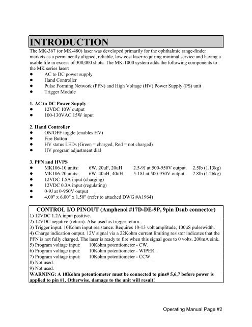
INTRODUCTION<br />
The <strong>MK</strong>-367 (or <strong>MK</strong>-480) laser was developed primarily for the ophthalmic range-finder<br />
markets as a permanently aligned, reliable, low cost laser requiring minimal service and having a<br />
usable life in excess of 300,000 shots. The <strong>MK</strong>-<strong>1000</strong> system adds the following components to<br />
the <strong>MK</strong> series laser:<br />
! AC to DC power supply<br />
! Hand Controller<br />
! Pulse Forming Network (PFN) and High Voltage (HV) Power Supply (PS) unit<br />
! Trigger Module<br />
1. AC to DC Power Supply<br />
! 12VDC 10W output<br />
! 100-130VAC 15W input<br />
2. Hand Controller<br />
! ON/OFF toggle (enables HV)<br />
! Fire Button<br />
! HV status LEDs (Green = charged, Red = not charged)<br />
! HV program adjustment dial<br />
3. PFN and HVPS<br />
! <strong>MK</strong>106-10 units: 6W, 20uF, 20uH 2.5-9J at 500-950V output. 2.5lb (1.13kg)<br />
! <strong>MK</strong>106-20 units: 6W, 40uH, 40uH 5-18J at 500-950V output. 2.8lb (1.26kg)<br />
! 12VDC 1.5A input (charging)<br />
! 12VDC 0.3A input (regulating)<br />
! 0-9J at 0-950V output<br />
! 4.00" x 6.00" x 1.50" (refer to attached DWG #A1964)<br />
CONTROL I/O PINOUT (Amphenol #17D-DE-9P, 9pin Dsub connector)<br />
1) 12VDC 1.2A input positive.<br />
2) 12VDC negative (return). Also used as trigger return.<br />
3) Trigger input. 10Kohm input resistance. Requires 10-13 volt amplitude, 100uS pulsewidth.<br />
4) Charge indication output. 12V signal via a 22Kohm current limiting resistor indicates that the<br />
PFN is not fully charged. The laser is ready to fire when this signal goes to 0 volts. 200mA sink.<br />
5) Program voltage input: 10Kohm potentiometer - CW.<br />
6) Program voltage input: 10Kohm potentiometer - WIPER.<br />
7) Program voltage input: 10Kohm potentiometer - CCW.<br />
8) Not used.<br />
9) Not used.<br />
WARNING: A 10Kohm potentiometer must be connected to pins# 5,6,7 before power is<br />
applied to pin #1. Otherwise, damage to the unit will result!<br />
Operating Manual Page #2