PATU 304, 304T 305, 305T
PATU 304, 304T 305, 305T
PATU 304, 304T 305, 305T

You also want an ePaper? Increase the reach of your titles
YUMPU automatically turns print PDFs into web optimized ePapers that Google loves.
<strong>PATU</strong><br />
<strong>304</strong>, <strong>304</strong>T<br />
<strong>305</strong>, <strong>305</strong>T<br />
GRAPPLE LOADER<br />
OPERATION<br />
MAINTENANCE<br />
SPARE PARTS<br />
Made by Kesla Oyj
TABLE OF CONTENTS<br />
1 SUMMARY................................................................................................................7<br />
2 GENERAL.................................................................................................................8<br />
2.1 ABOUT THIS MANUAL..........................................................................................8<br />
3 LOADER PRESENTATION ....................................................................................10<br />
3.1 INSTRUCTIONS AND WARNINGS ON LOADER ...............................................11<br />
3.1.1 Decal # 1 ......................................................................................................12<br />
3.1.2 Decal # 2 ......................................................................................................12<br />
3.1.3 Decal # 3 ......................................................................................................12<br />
3.1.4 Decal # 4 ......................................................................................................13<br />
3.1.5 Decal # 5 ......................................................................................................13<br />
3.1.6 Plate # 6 .......................................................................................................13<br />
3.1.7 Decal # 7 ......................................................................................................14<br />
3.1.8 Decal # 8 ......................................................................................................14<br />
3.1.9 Decal # 9 ......................................................................................................14<br />
3.1.10 Decal # 10 ....................................................................................................15<br />
3.2 MOUNTING ALTERNATIVES OF LOADER ........................................................15<br />
3.2.1 Rear axle mounting ......................................................................................15<br />
3.2.2 Mounting on a trailer frame...........................................................................16<br />
3.2.3 Mounting with loader mounting column ........................................................16<br />
3.2.4 Mounting on 3-point hitch .............................................................................16<br />
3.2.5 Mounting recommendations .........................................................................16<br />
4 ACCESSORIES ......................................................................................................17<br />
5 FUNCTION .............................................................................................................18<br />
5.1 FIELD OF APPLICATION.....................................................................................18<br />
5.2 OPERATING PRINCIPLE ....................................................................................18<br />
6 SAFETY INSTRUCTIONS ......................................................................................19<br />
6.1 GENERAL SAFETY INSTRUCTIONS..................................................................19<br />
6.2 SPECIAL SAFETY INSTRUCTIONS....................................................................21<br />
6.2.1 The tractor's 3-point hitch .............................................................................21<br />
6.2.2 Attachment parts for mounting on the tractor's rear axle..............................21<br />
6.2.3 Hydraulic system ..........................................................................................21<br />
6.3 MOUNTING ACCESSORIES AND STRUCTURE MODIFICATIONS ..................22<br />
6.4 MAINTENANCE AND REPAIRS ..........................................................................22<br />
6.5 STORAGE............................................................................................................23<br />
6.6 SAFETY INSTRUCTIONS FOR TRAFFIC ON PUBLIC ROADS .........................23<br />
6.7 SAFETY INSTRUCTIONS WHEN HANDLING OILS AND GREASES ................24<br />
7 INTRODUCTION.....................................................................................................25<br />
7.1 SPECIAL SAFETY INSTRUCTIONS....................................................................25<br />
7.1.1 Preparations at introduction..........................................................................25<br />
7.2 HOW TO CONNECT THE GRAPPLE LOADER TO THE TRACTOR..................26<br />
7.2.1 Safety instruction..........................................................................................26<br />
7.3 CONNECTING THE GRAPPLE LOADER TO THE 3-POINT HITCH ..................26<br />
7.4 CONNECTING THE GRAPPLE LOADER TO THE TRACTOR'S REAR AXLE<br />
WITH AN ATTACHMENT KIT. .............................................................................27<br />
7.5 MECHANIC ..........................................................................................................27<br />
7.5.1 Safety instruction..........................................................................................27<br />
7.6 INSPECTIONS PRIOR TO MOUNTING ..............................................................27<br />
7.7 MOUNTING THE FRONT RACK AND ROLL BAR ..............................................28<br />
7.8 HOW TO CONNECT THE GRAPPLE LOADER TO THE TRAILER BEAM (<strong>PATU</strong><br />
TIMBER TRAILER) ..............................................................................................28<br />
1
TABLE OF CONTENTS<br />
7.8.1 Safety instruction..........................................................................................28<br />
7.9 MOUNTING ON TRAILER BEAM WITH LOADER MOUNTING TRIANGLE .......29<br />
7.10 MOUNTING ON TRAILER BEAM WITH LOADER MOUNTING COLUMN..........30<br />
7.11 MOUNTING THE CONTROL VALVE...................................................................30<br />
7.11.1 Emergency stop ...........................................................................................31<br />
7.11.2 Covering of hydraulic hoses .........................................................................31<br />
7.11.3 Cylinder covering..........................................................................................31<br />
7.12 COUPLING THE HYDRAULIC SYSTEM .............................................................31<br />
7.12.1 General.........................................................................................................31<br />
7.12.2 Installation ....................................................................................................32<br />
7.12.3 Connecting of closed circuit (e.g. John Deere).............................................32<br />
7.13 DECALS ...............................................................................................................32<br />
8 INSPECTIONS........................................................................................................33<br />
8.1 MOUNTING INSPECTION ...................................................................................33<br />
8.2 ANNUAL INSPECTION........................................................................................33<br />
8.3 INSPECTOR ........................................................................................................33<br />
8.4 STORING THE RECORD ....................................................................................33<br />
8.5 HOW TO PERFORM THE INSPECTION.............................................................33<br />
8.5.1 Safety instruction..........................................................................................33<br />
8.5.2 Inspection.....................................................................................................33<br />
8.5.3 Controls........................................................................................................34<br />
8.5.4 Plates and decals .........................................................................................34<br />
8.5.5 Hydraulic hoses and pipes ...........................................................................34<br />
8.5.6 Load-bearing steel structures and welding seams .......................................34<br />
8.5.7 Pin lockings ..................................................................................................34<br />
8.5.8 Hydraulic system ..........................................................................................34<br />
8.6 TEST RUN ...........................................................................................................35<br />
9 TRAFFIC ON PUBLIC ROADS...............................................................................36<br />
9.1 TRANSPORT POSITION .....................................................................................36<br />
9.2 MAKE SURE THAT YOU HAVE FULL CONTROL OF FUNCTIONS AND<br />
STABILITY ...........................................................................................................36<br />
9.3 DRIVING, DRIVE SPEEDS AND PASSENGERS................................................36<br />
10 OPERATION...........................................................................................................37<br />
10.1 OPERATING THE LOADER ................................................................................37<br />
10.1.1 Safety instructions ........................................................................................37<br />
10.2 GENERAL ............................................................................................................38<br />
10.2.1 Operating principle of the grapple loader .....................................................38<br />
10.2.2 Choise of working place ...............................................................................38<br />
10.2.3 Timber hauling from the wood ......................................................................38<br />
10.3 WAY OF WORKING.............................................................................................38<br />
10.3.1 Special safety instruction..............................................................................38<br />
10.3.2 Working ........................................................................................................39<br />
10.4 INSTRUCTIONS FOR EMERGENCY STOP .......................................................39<br />
10.4.1 Risk of tipping over.......................................................................................39<br />
10.5 EMERGENCY STOP IN CASE OF HOSE BURST ..............................................40<br />
10.6 STOPPING IN CASE OF SPONTANEOUS FUNCTIONING OF LOADER..........40<br />
10.7 TRAINING ............................................................................................................40<br />
11 MAINTENANCE......................................................................................................41<br />
11.1 SAFETY INSTRUCTIONS....................................................................................41<br />
11.1.1 Safety instructions when handling oils and greases .....................................41<br />
2
TABLE OF CONTENTS<br />
11.2 LUBRICATION .....................................................................................................42<br />
11.2.1 Lubricating greases, general ........................................................................42<br />
11.2.2 Lubrication scheme ......................................................................................43<br />
11.2.3 Greasing the slew mechanism .....................................................................44<br />
11.2.4 Greasing the booms and cylinder links.........................................................44<br />
11.2.5 Greasing the boom extensions (only a loader with boom extension) ...........44<br />
11.2.6 Greasing the grapple....................................................................................44<br />
11.2.7 Lubricating the control valve.........................................................................44<br />
11.3 OIL CHANGE .......................................................................................................44<br />
11.3.1 Changing the slew mechanism oil ................................................................45<br />
11.3.2 Oil recommendation (slew mechanism all year around)...............................45<br />
11.4 HOW TO CHANGE OIL........................................................................................46<br />
11.4.1 Changing the hydraulic system oil................................................................46<br />
11.4.2 Oil recommendation (hydraulics)..................................................................47<br />
11.4.3 How to change oil.........................................................................................47<br />
11.5 ADJUSTMENTS...................................................................................................48<br />
11.5.1 Tightening the barrels of slewing cylinders...................................................48<br />
11.5.2 Tightening the mounting bolts of loader .......................................................48<br />
11.6 DISMANTLING THE SLEW MECHANISM...........................................................49<br />
11.6.1 Safety instructions ........................................................................................49<br />
11.6.2 Dismantling...................................................................................................49<br />
11.6.3 Adjusting the boom extension ......................................................................51<br />
11.6.4 Adjusting the chain tension (models with double extension P<strong>304</strong>T, P<strong>305</strong>T) 51<br />
11.6.5 Adjusting the gaps in the transfer boom .......................................................51<br />
11.6.6 Dismantling the transfer boom......................................................................52<br />
11.6.7 Adjusting the swing damper of link ...............................................................52<br />
11.7 DETERMINATION OF BUSHING WEAR.............................................................53<br />
11.7.1 Slew mechanism bushings...........................................................................53<br />
11.7.2 Bushings in boom joints ...............................................................................54<br />
11.8 REPAIR WELDINGS............................................................................................55<br />
11.8.1 Safety instructions ........................................................................................55<br />
11.8.2 General welding instructions ........................................................................55<br />
11.9 REPLACING BUSHINGS.....................................................................................56<br />
11.10 PRESSURE MEASURING ...................................................................................56<br />
11.10.1 Safety instruction..........................................................................................56<br />
11.10.2 Measuring.....................................................................................................56<br />
11.11 PRESSURE MEASURING SPOT P2 FOR CONTROL VALVE ROTEC /<br />
MONSUN-TISON / FINN-HYDRAULIC / BUCHER. .............................................57<br />
11.11.1 1.Measuring from pressure measuring coupling...........................................57<br />
11.11.2 2.Measuring from supply hose .....................................................................57<br />
11.12 REPLACING HYDRAULIC COMPONENTS ........................................................57<br />
11.13 STORING THE LOADER .....................................................................................58<br />
11.14 REUSING AFTER STORAGE..............................................................................58<br />
11.15 TENSIONING TORQUES FOR SCREWS AND NUTS ........................................59<br />
11.16 MAINTENANCE SCHEDULE...............................................................................60<br />
12 TROUBLE SHOOTING TABLE...............................................................................61<br />
12.1.1 Safety instruction..........................................................................................61<br />
13 DISCARDING THE MACHINE................................................................................63<br />
14 TECHNICAL SPECIFICATIONS.............................................................................64<br />
14.1 DIMENSIONS <strong>PATU</strong> <strong>304</strong> .....................................................................................65<br />
3
TABLE OF CONTENTS<br />
14.2 DIMENSIONS <strong>PATU</strong> <strong>304</strong>T ...................................................................................65<br />
14.3 DIMENSIONS <strong>PATU</strong> <strong>305</strong> .....................................................................................66<br />
14.4 DIMENSIONS <strong>PATU</strong> <strong>305</strong>T ...................................................................................66<br />
14.5 LOADING DIAGRAM <strong>PATU</strong> <strong>304</strong> / <strong>304</strong>T...............................................................67<br />
14.6 LOADING DIAGRAM <strong>PATU</strong> <strong>305</strong> / <strong>305</strong>T...............................................................67<br />
14.7 REACH DIAGRAM <strong>PATU</strong> <strong>304</strong>, <strong>304</strong>T ...................................................................68<br />
14.8 REACH DIAGRAM <strong>PATU</strong> <strong>305</strong>, <strong>305</strong>T ...................................................................69<br />
14.9 HYDRAULICS SETTINGS ...................................................................................70<br />
14.10 HD-SCHEME FINN HYD RS-218 JOYSTICK ......................................................71<br />
14.11 HD-SCHEME BUCHER HDS 15/8 .......................................................................72<br />
14.12 HD-SCHEME VALVOIL HYDRAULIC / ELECTROHYDR. REMOTE CONTROL 73<br />
14.13 HD-SCHEME / ELECTROHYDR. REMOTE CONTROL / W. FLOAT POSITIONS..<br />
.....................................................................................................................74<br />
15 DETERMINATION OF STABILITY..........................................................................75<br />
15.1 DETERMINATION OF STABILITY BY CALCULATION .......................................75<br />
15.1.1 Symbol definitions ........................................................................................75<br />
15.2 CALCULATION FORMULAS ...............................................................................77<br />
15.2.1 When loading from the side (drawing 1).......................................................77<br />
15.2.2 When loading from the rear (drawing 2) .......................................................78<br />
15.2.3 Loader on trailer beam (drawing 3) ..............................................................78<br />
15.3 DETERMINATION OF STABILITY BY TEST .......................................................80<br />
15.3.1 Safety instruction..........................................................................................80<br />
15.3.2 Test conditions .............................................................................................80<br />
15.3.3 Performing the test .......................................................................................80<br />
15.3.4 Result evaluation..........................................................................................80<br />
16 DIRECTIVES AND STANDARDS APPLIED...........................................................81<br />
17 TERMS OF WARRANTY ........................................................................................82<br />
17.1 RESPONSIBILITY FOR DAMAGE.......................................................................82<br />
18 WARRANTY ...........................................................................................................83<br />
19 BILL OF DELIVERY ................................................................................................84<br />
19.1 BILL OF DELIVERY / OWNERS / POSSESSORS ASSURANCE OF HAVING<br />
READ AND UNDERSTOOD THE MANUAL ........................................................84<br />
20 EU-DECLARATION OF CONFORMITY FOR MACHINERY ..................................85<br />
21 REPORT OF THE TEST RUN AND INSPECTION PROCEEDINGS - GRAPPLE<br />
LOADERS...............................................................................................................86<br />
4
REPORT OF THE TEST RUN AND INSPECTION PROCEEDINGS<br />
KESLA OYJ<br />
Metsolantie 2<br />
FIN-59800 KESÄLAHTI<br />
Tel. int. +358 (0)13 682841<br />
Fax int. + 358 (0)13 6828100<br />
REPORT OF THE TEST RUN AND INSPECTION PROCEEDINGS - GRAPPLE<br />
LOADERS<br />
(Record the proceedings thoroughly. The report shall be stored together with the machine<br />
for a minimum period of five years, counting from the latest inspection.)<br />
Inspected by the<br />
X<br />
CE marking: yes X<br />
manufacturer<br />
Mounting inspection<br />
Maintenance inspection / 20<br />
Place of inspection: KESÄLAHTI Inspector:<br />
Signature and signer:<br />
Inspector’s address:<br />
KESLA OYJ, KESÄLAHTI<br />
Basic data on the<br />
machine Make and model: <strong>PATU</strong> <strong>304</strong><br />
<strong>PATU</strong> <strong>304</strong>T<br />
Place of manufacturing: KESÄLAHTI <strong>PATU</strong> <strong>305</strong><br />
<strong>PATU</strong> <strong>305</strong>T<br />
Country of delivery and language:<br />
Serial no. / Model year:<br />
Type of control valve:<br />
A-frame: yes no Attachment kit: yes no X<br />
Type of timber<br />
grapple:<br />
Type of rotator:<br />
Other equipment:<br />
OBSERVED DEFECTS AND REMARKS<br />
5
REPORT OF THE TEST RUN AND INSPECTION PROCEEDINGS<br />
ISSUES TO INSPECT YES = IN ORDER<br />
(Refer to instructions on inspection later on in this manual) NO = TO BE ATTENDED TO<br />
1. STRUCTURE 2. TEST RUN / LOADING<br />
YES NO YES NO<br />
1. Welding seams 1. Pressure settings<br />
2. Surface treatment 2. Sealing<br />
3. Pin lockings 3. Operating movements and limit<br />
positions<br />
4. Hydraulic hoses and pipes 4. Control valve; function<br />
5. El. cables and connections 5. Test loading with SWL<br />
6. Straightness of the booms 6. Test loading with overload<br />
7. Chain tension of outer boom <strong>PATU</strong> <strong>304</strong><br />
extension<br />
8. Fitting of controls Overload = SWL 510 kg x 1,25 = 638kg<br />
9. Greasing (Extra weight to grapple=638kg-95kg)= 543kg<br />
10. Oil filling<br />
11. Mounting bolts of slew<br />
mechanism<br />
12. Plates and decals<br />
13. Owner’s manual<br />
14. The theoretic stability of the unit 7. Load run off mm<br />
8. The unit stability determined by test<br />
OBSERVED DEFECTS AND REMARKS:<br />
YES<br />
NO<br />
3. REPAIRS CARRIED OUT AFTER<br />
PREVIOUS INSPECTION<br />
1. Welding<br />
2. Other repairs<br />
3. Test loading with overload<br />
The observed faults and defects shall be attended to no later than / 20<br />
The observed faults and defects have been attended to / 20<br />
Signature<br />
Signer<br />
ENCL.: P.T.O. for more remarks DISTR.: Manufacturer X<br />
X Instructions on inspection Owner’s manual X<br />
Inspector<br />
6
SUMMARY<br />
1 SUMMARY<br />
1. As the very first step read the manual. The operator shall be well familiarized with its<br />
instructions for operation and safety.<br />
2. Check that the hydraulics and stability of the base machine are appropriate.<br />
3. Follow the mounting instructions. The seller and manufacturer will be pleased to give<br />
you further information, if needed.<br />
4. Do not forget the inspections provided in law.<br />
5. Practice makes perfect.<br />
6. Always work with good judgement.<br />
7. Do not forget to “limber up“ the hydraulic system in freezing conditions.<br />
8. Grease often and some instead of infrequently and much.<br />
9. Cleanness is essential for the hydraulic system.<br />
10. First filling oil: Esso Unifarm 10W/30.<br />
11. Repair even minor faults immediately before they cause serious damage.<br />
7
GENERAL<br />
2 GENERAL<br />
With this manual as your guidance you will be able to operate the Patu grapple loader in<br />
the right and safe way. The tractor manual gives you the key data on the base machine's<br />
hydraulics, couplings and on the right working position in regard to safety.<br />
For realization of an effective short distance transport the general instructions on<br />
harvesting will be of assistance when planning the timber felling site properly.<br />
Signs and symbols of the manual<br />
*) The asterisk notifies information on the issue at hand.<br />
-) The dash indicates necessary/possible steps to be taken.<br />
WARNING !<br />
The WARNING! symbol denotes a very important safety<br />
instruction.<br />
ALERT !<br />
The ALERT! symbol notifies risk of damage for the product,<br />
process or environment<br />
2.1 ABOUT THIS MANUAL<br />
* All descriptions, instructions and technical data are based on the latest knowledge of the<br />
machine structure at hand when preparing the manual. Due to continuous product<br />
developing the manufacturer reserves the right to change the product without advance<br />
notice.<br />
* Should malfunction occur, the trouble and its probable cause can be cleared and<br />
repaired with the assistance of the Trouble shooting table. If not, contact the manufacturer<br />
or a maintenance shop authorized by the manufacturer.<br />
NOTICE!<br />
When ordering spare parts or asking for repair instructions always supply the information<br />
from the machine plate to get speedier help in case of malfunction and the correct spare<br />
part.<br />
8
GENERAL<br />
NOTE!<br />
Copy the information on the machine plate onto the picture below:<br />
SF-59800 Kesälahti Finland<br />
013 - 682 841<br />
Tyyppi<br />
Typ<br />
Type<br />
Valm.No<br />
Tillv. nr<br />
Serial No<br />
Paino<br />
Vikt<br />
Weight<br />
Valm. V.<br />
Tillv. år<br />
Year<br />
Nosturil.<br />
Kranklass<br />
Loader class<br />
3280507<br />
kg<br />
9
LOADER PRESENTATION<br />
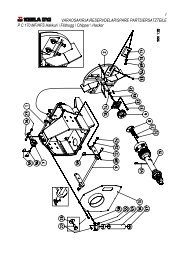
3 LOADER PRESENTATION<br />
1. Slewing mechanism<br />
2. Pillar<br />
3. Main lifting cylinder<br />
4. Main lifting boom<br />
5. Outer boom<br />
6. Grapple<br />
7. Rotator<br />
8. Link with swing damper<br />
9. Outer boom extension<br />
10. Outer boom cylinder<br />
11. Slewing cylinders<br />
12 Case for manual<br />
13. Mounting rack<br />
14. Control valve<br />
10
LOADER PRESENTATION<br />
LOADER PRESENTATION<br />
3.1 INSTRUCTIONS AND WARNINGS ON LOADER<br />
Warnings and instructions informing of hazards or operational directions appear on the<br />
numbered spots on the loader. Follow these to avoid uncalled-for accidents and<br />
malfunctions.<br />
7<br />
1<br />
4<br />
3<br />
10<br />
2<br />
6<br />
5<br />
8<br />
11
LOADER PRESENTATION<br />
3.1.1<br />
Decal # 1<br />
RISK ZONE 20M 60FT<br />
* Risk zone decal<br />
* The decal notifies the risk zone radius measured from the slewing centre of loader.<br />
* The risk zone must always absolutely be clear of any person when lifting.<br />
3.1.2<br />
Decal # 2<br />
* The decal remainds the operator not to start-up, mount,<br />
maintain or repair the machine before the manual has been<br />
carefully read and understood.<br />
* If the machine is operated by more than one person, the<br />
owner/possessor shall instruct them all to operate, mount,<br />
maintain and repair the machine and also oblige them to<br />
read and understand the manual.<br />
!<br />
* The owner/possessor shall fill out the Bill of Delivery and<br />
the Assurance of having read and understood the manual,<br />
3280523<br />
and send these both documents to the manufacturer no<br />
later than fourteen (14) days since machine delivery from seller to customer (refer to<br />
Terms of Warranty). The address is: Kesla Oyj, Metsolantie 2, FIN 59800 Kesälahti<br />
(Finland). (Fax +358 13 6828100, phone +358 13 682841).<br />
3.1.3 Decal # 3<br />
* Load plate<br />
* The plate notifies the safe<br />
working load for each lifting<br />
radius, measured from the<br />
slewing centre, at the end of the<br />
boom extension, less timber<br />
grapple, rotator and link.<br />
E.g. with a 4,0 m radius the permissible load is 940 kg. (Patu <strong>304</strong>)<br />
* The total weight of timber grapple, rotator and link is 143 kg.<br />
* The net lifting capacity incl. grapple equipment, e.g. with a 4,0 m radius is 940 kg - 143<br />
kg = 797 kg.<br />
The picture of the lifting hook in the plate indicates that it is forbidden to use the log loader<br />
for handling piece goods (standard EN 12999).<br />
12
LOADER PRESENTATION<br />
3.1.4<br />
Decal # 4<br />
* Scheme decal for controls<br />
* The decal shows the functions of different lever positions of control valve. When e.g.<br />
pulling the right side lever the main lifting boom will rise.<br />
3.1.5<br />
Decal # 5<br />
* Product decal<br />
* The decal notifies the loader name and model.<br />
3.1.6 Plate # 6<br />
* Machine plate<br />
* Weight: Includes the slew mechanism (less stabilizer legs), pillar, booms, cylinders,<br />
timber grapple, rotator incl. link, control<br />
valve incl. hydraulic hoses, mounting rack,<br />
the slew mechanism oils and the test run<br />
oils in cylinders and hoses.<br />
* HC1 loader class: for handling round<br />
timber on farms.<br />
* CE: Marking referred to in Article 10 of<br />
Council Directive 89/392/EEC and<br />
amendments.<br />
* Model: Product name<br />
Tyyppi<br />
Typ<br />
Type<br />
Valm.No<br />
Tillv. nr<br />
Serial No<br />
SF-59800 Kesälahti Finland<br />
013 - 682 841<br />
Paino<br />
Vikt<br />
Weight<br />
Valm. V.<br />
Tillv. år<br />
Year<br />
Nosturil.<br />
Kranklass<br />
Loader class<br />
3280507<br />
kg<br />
13
LOADER PRESENTATION<br />
3.1.7<br />
Decal # 7<br />
* Lifting point decal<br />
* The decal shows the lifting points for a loader not mounted or<br />
in transport package.<br />
* The lifting points will not prevail, when the loader is mounted<br />
on tractor, trailer or any other machine unit.<br />
3280444<br />
3.1.8<br />
Decal # 8<br />
* Decal for instruction book<br />
* Decal reveals the location of the instructions book<br />
* The instruction book must always remain with the loader and<br />
be available for the operator<br />
3.1.9 Decal # 9<br />
3280297<br />
* Warning decal<br />
* The decal notifies the minimum safe approach distances<br />
from the loader component or the load to uninsulated or<br />
insulated live electrical conductors with different conductor<br />
voltages.<br />
* The decal notifies the minimum safe approach distances<br />
from the loader component or the load to uninsulated or<br />
insulated live electrical conductors with different conductor<br />
voltages.<br />
VARNING WARNING<br />
Nominell<br />
spänning<br />
Nominal<br />
Tension<br />
U<br />
kv<br />
U
LOADER PRESENTATION<br />
3.1.10<br />
Decal # 10<br />
* Prohibiting decal<br />
* The decal forbids using the loader as a piece good crane.<br />
3.2 MOUNTING ALTERNATIVES OF LOADER<br />
You can either mount Patu grapple loaders on the tractor's 3-point hitch, on the tractor's<br />
rear axle with special attachment kit for each make, or on the beam of a Patu timber trailer.<br />
When mounting on a trailer you need attachment parts like a mounting column, which you<br />
can get as an option. When the loader is equipped with its own A-frame it can be mounted<br />
directly on the trailer beam.<br />
3.2.1<br />
Rear axle mounting<br />
1<br />
1. Mounting bolts of loader<br />
2. Loader mounting console,<br />
specified for each tractor<br />
model<br />
2<br />
K1038008<br />
K1038007<br />
15
LOADER PRESENTATION<br />
3.2.2<br />
Mounting on a trailer frame<br />
1<br />
2<br />
1. Mounting bolts of loader<br />
2. A- Frame<br />
3. Mounting bolts<br />
4. Patu- trailer<br />
3<br />
4<br />
mounting column<br />
3.2.3<br />
Mounting with loader<br />
1. Mounting bolts of loader<br />
2. Loader mounting column<br />
3. Mounting bolts of loader mounting<br />
column<br />
4. Patu- trailer<br />
3.2.4<br />
Mounting on 3-point hitch<br />
The loader frame includes lugs that allow it to be attached to a tractor’s three-point hitch.<br />
Only use the lugs to transfer the loader. Never use the loader to lift anything when it is<br />
attached to the hitch, as this may damage the hitch or the loader frame and tilt the loader.<br />
3.2.5<br />
Mounting recommendations<br />
Patu 201, 202, 202T, 203, 203T grapple loaders / Patu 8T timber trailer.<br />
Patu <strong>304</strong>, <strong>304</strong>T, <strong>305</strong> and <strong>305</strong> T grapple loaders / Patu 10T, 10HD, 12MD, 12MD timber<br />
trailers<br />
Never connect a grapple loader to the beam of a lighter class trailer. This means that e.g.<br />
the machine unit of Patu <strong>304</strong> / Patu 8T is forbidden.<br />
16
ACCESSORIES<br />
4 ACCESSORIES<br />
Thanks to its versatile assortment of accessories the Patu grapple loader can be applied to<br />
most various lifting tasks which the farmer will run into.<br />
- Hydraulic winch with a traction force of 13700 N (1400 kg), to be attached to the booms<br />
The booms do not have attachment lugs for the winch as standard equipment. Lugs can<br />
be welded to the booms, if necessary<br />
- Forage/Fertilizer grab, to be attached to the Patu timber grab<br />
- Gravel clamshell bucket, to be attached to the Patu timber grab<br />
- Rear axle attachment parts for each make/A models<br />
- Valve mounting support<br />
17
FUNCTION<br />
5 FUNCTION<br />
5.1 FIELD OF APPLICATION<br />
The grapple loaders Patu <strong>304</strong>, <strong>304</strong>T, <strong>305</strong> and <strong>305</strong>T cover the needs in farming and<br />
forestry and they are especially useful for loading and lifting round timber, forage, manure,<br />
sand, loose fertilizer, fertilizer sacks etc.<br />
In forestry use the grapple loaders are suited for the farmer's own harvesting in thinning<br />
stands and also for lighter professional work.<br />
5.2 OPERATING PRINCIPLE<br />
The operator guides the loader movements with a control valve. The valve transfers the<br />
hydraulic pressure, generated by the tractor, to the hydraulic cylinders of the loader, thus<br />
bringing about the wanted functions; slewing of booms, lifting of main lifting boom ,<br />
compression of grapple etc. The loader valve is fitted with relief valves to prevent<br />
overloading of the grapple loader.<br />
18
SAFETY INSTRUCTIONS<br />
6 SAFETY INSTRUCTIONS<br />
6.1 GENERAL SAFETY INSTRUCTIONS<br />
WARNING !<br />
* The Patu loader is designed for normal use in farming and<br />
forestry. The persons permitted to operate the loader must have<br />
general knowledge of handling farm machines.<br />
* Read the tractor manual before you connect the loader to the tractor hydraulic system. If<br />
the hydraulic system has a variable displacement pump, the loader control valve has to be<br />
modified. Contact the seller or manufacturer before you connect the loader to the tractor.<br />
The control valve is factory connected for constant flow.<br />
* Get familiar with the loader, loader functions, controls and manuals prior to introduction.<br />
Do not ever use the loader unless you first have read and understood the instructions for<br />
operation and safety.<br />
* Follow all safety and operating instructions appearing on the machine to avoid accidents<br />
when working.<br />
* Be very careful when connecting and disconnecting the loader to and from the tractor or<br />
trailer.<br />
* Ensure that the loader's risk zone is clear of any person when working.<br />
* Keep hands and other parts of the body away from the machine or from under the load<br />
when working. Also ensure that there is no risk for you of getting jammed between the<br />
loader structures or between the tractor and trailer. RISK TO GET JAMMED!<br />
* Make sure that the supporting ground under the loader is so stable that no risk of tipping<br />
over will come about. Neither may the ground under the stabilizer legs yield when lifting<br />
nor the loader begin to slide.<br />
* Do not start the tractor unless the hydraulic pressure to the loader is disconnected.<br />
* Never leave the tractor running and unattended.<br />
* When you finish your work, lower the loader and grapple onto a firm ground, shut off the<br />
engine, engage the parking brake and remove the key to prevent unauthorized use.<br />
* Do not ever ignore the minimum safe approach distances to live electrical conductors<br />
when operating the loader.<br />
* A defective loader may cause accidents due to sudden machine breakdown. Therefore<br />
the loader must always be in full order when operated.<br />
* Never let the loader to an outsider unless you have made sure that he is familiar with the<br />
operating and safety instructions.<br />
19
SAFETY INSTRUCTIONS<br />
* Prior to maintenance and reparation lower the grapple or the boom end onto a firm<br />
ground so that no machine component will be supported by the hydraulic cylinders solely.<br />
Shut off the tractor engine, disengage the loader's hydraulic pressure, engage the parking<br />
brake and remove the key from the ignition to prevent unintentional loader movements.<br />
* A person being under the influence of alcohol or drugs may under no circumstances<br />
handle, maintain or repair the loader. (Very dangerous / Penal law)<br />
20
SAFETY INSTRUCTIONS<br />
6.2 SPECIAL SAFETY INSTRUCTIONS<br />
6.2.1<br />
The tractor's 3-point hitch<br />
WARNING !<br />
Follow the safety instructions given below when connecting the<br />
loader to the tractor's 3-point hitch.<br />
* Check for the appropriate carrying capacity of all tractor hitches during loader use.<br />
* Check for any deformations or breaks in hitch components and ensure that the side<br />
stabilizers are in order. Replace defective parts.<br />
* The top link used shall be in good condition and heavy enough.<br />
* Make sure that the draft control of the three-point hitch absolutely is locked when the<br />
loader is mounted on the hitch.<br />
* To avoid the risk of getting jammed observe extra caution, when connecting the loader to<br />
the hitch.<br />
6.2.2<br />
Attachment parts for mounting on the tractor's rear axle<br />
WARNING !<br />
Follow the safety instructions given below when connecting the<br />
loader on the attachment parts mounted on the tractor's rear axle.<br />
* Check for the carrying capacity of the tractor prior to rear axle mounting.<br />
* Check for the stability of the machine unit before introducing the loader. Use, if<br />
necessary, extra weights for achieving appropriate stability. (Instructions for determination<br />
of stability by calculation on page 77)<br />
* Check the torque of the mounting bolts of the attachment parts according to Maintenance<br />
instructions. An inadequate torque might cause breakdown of the tractor or the attachment<br />
parts and therefore give rise to risk of accidents.<br />
6.2.3<br />
Hydraulic system<br />
WARNING !<br />
Follow prevailing safety instructions when attaching and using the<br />
loader hydraulics.<br />
* Do not start the tractor unless having disengaged the hydraulic pressure to the loader.<br />
* Support the loader while maintaining and repairing so that no machine part will be<br />
depending on a hydraulic cylinder solely.<br />
* Do not ever alter the pressure settings of the relief valves in the control valve. An<br />
increased pressure setting will cause a situation of overload in the loader.<br />
RISK OF ACCIDENT!<br />
21
SAFETY INSTRUCTIONS<br />
* Keep the loader hydraulic hoses and pipes in appropriate condition and replace the<br />
defective components. Defects in pipe or hose might cause that high pressurized oil will<br />
spout out, be injected into the skin and so give rise to a severe infection. In such a case<br />
you have to contact a physician immediately.<br />
* Check for the proper location and condition of the cover plate mounted on the control<br />
valve to block the oil spout.<br />
* Be very cautious when restarting the hydraulic system after reparations or if air on any<br />
other ground might have entered the system. Air in the hydraulic system might cause<br />
unexpected loader movements. RISK OF ACCIDENT!<br />
* When replacing hydraulic components, pipes and hoses with new ones check for their<br />
appropriate pressure durability.<br />
6.3 MOUNTING ACCESSORIES AND STRUCTURE<br />
MODIFICATIONS<br />
* Always contact Kesla Oyj before mounting an accessory not manufactured by Kesla Oyj.<br />
The accessory might be inappropriate and thus cause risk of machine breakdown or<br />
accident.<br />
* Prior to any structure modification always contact the factory. Structure modification<br />
might cause situations of overload and therefore risk of accidents.<br />
6.4 MAINTENANCE AND REPAIRS<br />
* During maintenance and repairs the loader shall be firmly lowered<br />
WARNING ! onto the ground so that no machine part will be depending on the<br />
hydraulic cylinder solely. Shut off the tractor engine, engage the<br />
parking brake and remove the key from the ignition.<br />
* If you have to repair weld the structure, never start to weld before having been in contact<br />
with the factory to get necessary welding instructions and other facts to be noticed.<br />
Reparations by welding shall be performed by a qualified welder, since a sudden<br />
breakdown of an inadequately repaired structure might give rise to accidents.<br />
* When repairing or maintaining the control valve, any other than original spare parts are<br />
unthinkable. Do not ever alter the pressure settings of the relief valves in the control valve.<br />
Increased pressure setting might lead to a situation of overload, which might cause a<br />
machine breakdown. RISK OF ACCIDENT!<br />
22
SAFETY INSTRUCTIONS<br />
6.5 STORAGE<br />
WARNING !<br />
* Ensure before lowering the loader onto the storing ground that it will not yield during<br />
storage because of e.g. thawing ground or rain.<br />
* Position the booms and grapple into transport position.<br />
* Check for the supporting to avoid the loader to tip over when stored.<br />
* When stored, make sure that the loader cannot be used as a childrens' playground.<br />
* When stored, the inclination angle of the loader may not exceed 25º. Otherwise the oil<br />
might flow out from the slew mechanism.<br />
6.6 SAFETY INSTRUCTIONS FOR TRAFFIC ON PUBLIC<br />
ROADS<br />
WARNING !<br />
* Before driving away position the loader into transport position.<br />
* When starting to drive make sure that you have complete control of the machine unit in<br />
all situations. Also observe that the braking distance is longer.<br />
* Follow the given minimum safe approach distances to live electrical conductors when<br />
trafficing near electric or telephone lines.<br />
* Observe the machine unit height when driving under flyover junctions.<br />
* Observe special caution when driving in turns or slopes, on yielding ground or icy roads.<br />
The tractor's and loader's joint center of gravity lies higher than the tractor's alone. Risk of<br />
tipping over!<br />
* Comply with all the statutes and decrees of the Road Traffic Law when driving on public<br />
roads.<br />
* Before starting to drive make sure that all necessary equipment, lights, reflectors and the<br />
SMV triangle are in correct places and functioning.<br />
* Also check the tire pressure.<br />
* Never under any circumstances drive under the influence of alcohol or drugs.<br />
23
SAFETY INSTRUCTIONS<br />
6.7 SAFETY INSTRUCTIONS WHEN HANDLING OILS AND<br />
GREASES<br />
WARNING !<br />
* Avoid skin contact with oil or grease when working or maintaining. These might contain<br />
additives harmful when continuously in skin contact. Follow the instructions and<br />
regulations of the manufacturers and authorities.<br />
* Always wear proper protective clothing, skin protecting lotions or appropriate gloves<br />
when handling oils and greases.<br />
* Never use lubricating oils or greases to clean your hands with. Metal particles and<br />
additives of the lubricants might damage the skin.<br />
* Never use clothes soiled with oils and greases.<br />
* Do not keep oily tools or other oily objects in the pockets.<br />
* If oil or grease result in skin changes, contact a physician immediately.<br />
* All waste oil from maintenance and repair shall be sent away to be duly treated.<br />
24
INTRODUCTION<br />
7 INTRODUCTION<br />
This section of the manual deals with the preparations and special safety instructions prior<br />
to start-up.<br />
7.1 SPECIAL SAFETY INSTRUCTIONS<br />
WARNING !<br />
* Make sure you know how to quickly shut off the tractor engine to prevent oil flowing onto<br />
the ground e.g. because of hose breakdown.<br />
* Observe extreme caution when connecting the loader to the tractor or trailer.<br />
* Ensure the appropriate stability of the connected machine unit in all situations.<br />
(Instructions for determination by calculation, page 77.)<br />
* Ensure that the risk zone of the tractor and loader is clear of unauthorized persons while<br />
connecting and operating.<br />
* Before you begin to work, get familiar with the functions of the control levers.<br />
7.1.1 Preparations at introduction<br />
* How to connect the grapple loader to the tractor<br />
* How to connect the grapple loader to the trailer beam<br />
* Mounting the front rack and roll bar<br />
* Removing and installing an additional lug<br />
* Covering of hydraulic hoses<br />
* Cylinder covering<br />
* Coupling the hydraulic system<br />
* Decals<br />
25
INTRODUCTION<br />
7.2 HOW TO CONNECT THE GRAPPLE LOADER TO THE<br />
TRACTOR<br />
7.2.1 Safety instruction<br />
WARNING !<br />
* When connecting the loader to the tractor, you have to work between the machines.<br />
There is a risk of getting jammed, so be extra cautious!<br />
There are two ways of connecting the grapple loader to the tractor: to the 3-point hitch or<br />
to the tractor rear axle by using an attachment kit.<br />
7.3 CONNECTING THE GRAPPLE LOADER TO THE 3-<br />
POINT HITCH<br />
1<br />
1. Top link<br />
2. Lower links<br />
2<br />
Only use the tractor’s three-point hitch to transfer the loader. Never use the loader to lift<br />
anything when it is attached to the hitch, as this may damage the hitch or the loader frame<br />
and tilt the loader.<br />
- Release the side stabilizers of the lower links.<br />
- Attach the lower links to the brackets located in the grapple loader A-frame.<br />
- Fasten the top link into its bracket, located on the tractor, so that the bracket end lies as<br />
close as possible to the place, where the bracket is fastened onto the frame. This kind of<br />
proceeding will result in smallest possible load on the top link bracket. Refer to drawing.<br />
- Many times it is easier to mount the top link to the loader by connecting the pressure and<br />
return hoses to the tractor (read the instructions first!) and then fasten the top link by<br />
positioning the loader with the boom. Use the top link for upright positioning of the loader.<br />
- Lock the carrier pins of the loader with ring cotters and lock the side stabilizers.<br />
- The draft control of the top link shall be locked, when the loader is connected to the 3-<br />
point hitch.<br />
26
INTRODUCTION<br />
7.4 CONNECTING THE GRAPPLE LOADER TO THE<br />
TRACTOR'S REAR AXLE WITH AN ATTACHMENT KIT.<br />
1<br />
1. Mounting bolts of loader<br />
2. Loader mounting console,<br />
specified for each tractor model<br />
2<br />
K1038008<br />
K1038007<br />
For this mounting alternative you will need a separate attachment kit for each tractor.<br />
Mounting instructions are included in the attachment kit delivery.<br />
7.5 MECHANIC<br />
7.5.1 Safety instruction<br />
WARNING !<br />
Only the manufacturer or a maintenance shop authorized by him is permitted to perform<br />
the mounting. The mechanic shall be appropriately experienced in loader mountings.<br />
7.6 INSPECTIONS PRIOR TO MOUNTING<br />
- Do not start mounting the loader on the frame unless having checked that it will be able<br />
to turn the back way around.<br />
- Clean the frame threads and check that the mounting bolts are of strength class 10.9<br />
and size M20-70 (M24-80 Patu <strong>305</strong>). The M20 (M24 Patu <strong>305</strong>) mounting bolts must be<br />
tightened to a torque of 540 Nm (930 Nm Patu <strong>305</strong>). Install M20 (M24 Patu <strong>305</strong>) spring<br />
washers under the bolts.<br />
27
INTRODUCTION<br />
7.7 MOUNTING THE FRONT RACK AND ROLL BAR<br />
The tractor shall be fitted with a rack, where the loader grapple can easily be fastened for<br />
transport. The rack incl. its fixing points shall withstand the stresses the loader will cause<br />
when driving in rough terrain. Ensure when assembling the front rack that neither the rack<br />
or the grapple will hide the head lights or registration number from view.<br />
The slewing, lifting and outer boom functions of all tractor-mounted loaders are fitted with<br />
valve spool with so called floating position and therefore the grapple can during transport<br />
be fastened onto the load too.<br />
When lifting from the front the lift boom will go so far down that the cab might get<br />
damaged. Therefore you have to cover the cab with a roll bar to prevent the lift boom to<br />
lower as far as onto the cab. Never mount the roll bar on the cab and ensure that it will not<br />
hinder the driver to get out through the sun roof.<br />
7.8 HOW TO CONNECT THE GRAPPLE LOADER TO THE<br />
TRAILER BEAM (<strong>PATU</strong> TIMBER TRAILER)<br />
7.8.1 Safety instruction<br />
WARNING !<br />
* When connecting the loader to the trailer beam you have to work between the machines.<br />
Risk of getting jammed!<br />
There are two ways of connecting the loader to the trailer beam, depending on whether the<br />
loader has stabiliser legs or not. If the loader has stabiliser legs, it can be attached directly<br />
to the trailer beam. If the loader does not have stabiliser legs, use a loader mounting<br />
column between the loader and the trailer beam.<br />
28
INTRODUCTION<br />
7.9 MOUNTING ON TRAILER BEAM WITH LOADER<br />
MOUNTING TRIANGLE<br />
1<br />
2<br />
1. Mounting bolts of loader<br />
2. A - frame<br />
3. Mounting bolts<br />
4. Patu trailer<br />
3<br />
4<br />
- Lower the trailer hook onto the ground.<br />
- Reverse the loader, which has been attached to the tractor’s three-point hitch, on to the<br />
loader mounting plate that has been mounted on the trailer beam, and press the loader<br />
grapple on to the frame tube behind the trailer’s crossbeam.<br />
- Detach the push arm from the loader and lower the loader slowly so that the holes in the<br />
frame and in the loader mounting plate coincide with each other. Operate the extension<br />
cylinder in order to align the holes in the forward/backward direction, if necessary.<br />
- Attach the loader frame to the loader mounting plate using four M24x60 8.8 hexagonalheaded<br />
bolts (threaded holes) and four M24x90 8.8 (through holes) hexagonal-headed<br />
bolts. Install spring washers under the bolts and use M24 Nyloc nuts to secure the through<br />
bolts in position.<br />
- All the eight bolts/nuts must be tightened to a torque of 700 Nm.<br />
- Lift the trailer’s towing eye to the required height using the loader’s stabilisers.<br />
- Attach the trailer’s towing eye to the tractor’s towing hook.<br />
29
INTRODUCTION<br />
7.10 MOUNTING ON TRAILER BEAM WITH LOADER<br />
MOUNTING COLUMN<br />
1. Mounting bolts of loader<br />
2. Loader mounting column<br />
3. Mounting bolts of mounting<br />
column<br />
4. Patu trailer<br />
- Position the trailer with the beam lying horizontally.<br />
- Clean the upper surface and the threaded holes in the upper flange located in the loader<br />
mounting column, which is fastened on the trailer beam.<br />
- Lift the loader very carefully onto the end of the loader mounting column. Ensure that the<br />
lifting equipment used is realible and of appropriate lifting capacity.<br />
- Place the holes of the mounting flanges and turn all loader mounting bolts, 8 pcs<br />
M20x70, strength 10.9, gently to bottom.<br />
- Ensure that the mounting flanges lie tightly against each other.<br />
- Tighten the mounting bolts crosswise in two phases to torque 540 Nm (400 lbft).<br />
7.11 MOUNTING THE CONTROL VALVE<br />
Try to install the control valve so that the control levers are positioned upright and the<br />
height and distance will be convenient for the operator.<br />
- Try, if possible, to mount the valve housing outside the cab to avoid the oil spout in case<br />
of possible hose burst.<br />
- Ensure through firm mounting that the valve will neither move when driving in terrain nor<br />
sway during the work.<br />
- If there is no suitable valve mounting bar in the tractor cab, use the telescope tube<br />
enclosed to the delivery as a mounting rack. Fasten the telescope tube outside the cab<br />
between the tractor mudguards.<br />
30
INTRODUCTION<br />
1<br />
1. Mudguards of tractor<br />
2. Fixing screws<br />
3. Telescope tube<br />
2<br />
3<br />
K1037012<br />
K1037011<br />
7.11.1<br />
Emergency stop<br />
There must be an emergency stop in the tractor cabin (standard EN12999), which stops<br />
the oil flow to the loader. E.g. tractor’s stop control can be used as an emergency stop, if it<br />
is within reach and clearly marked.<br />
7.11.2<br />
Covering of hydraulic hoses<br />
If you have to lead hydraulic hoses into the cab, you must absolutely cover them so that<br />
the oil spout will not hit the operator in case of hose burst.<br />
- Place and cover the hoses so that they are not exposed to uncalled-for friction or<br />
deformation and that they cannot get jammed when using the hitch or some other<br />
accessory.<br />
7.11.3<br />
Cylinder covering<br />
- The rods in the cylinders are factory covered with storage grease, which shall be<br />
removed prior to introduction of the loader. The thick grease with its sticked impurities<br />
might damage the seals.<br />
7.12 COUPLING THE HYDRAULIC SYSTEM<br />
7.12.1 General<br />
Do not connect the grapple loader to the tractor unless you have ensured the compatibility<br />
of the oils. The loader is factory trial run with Esso Unifarm 10W/30 oil, which comes up<br />
the requirement API, SE, CC, CD and AP GL-4 and also is suitable for wet brakes. When<br />
delivered the grapple loader has an oil quantity of about 14 l ( 3.7 gal US).<br />
If the tractor and the grapple loader use separate hydraulic systems, you can be less<br />
precise when choosing oil for the loader. You will find the oil recommendations in the<br />
Maintenance instructions.<br />
Observe cleanness when coupling the hydraulic system. Contaminants will cause quick<br />
wear and malfunctions.<br />
31
INTRODUCTION<br />
7.12.2 Installation<br />
The supply (R½“) and return hose (R¾”) of the control valve are fitted with a ½“ quick<br />
coupling. Connect the supply hose either to a single or double acting outlet. The quick<br />
coupling of the pressure hose is marked with red paint. Should the tractor not already have<br />
an effective enough filter, we recommend that the return hose is connected directly<br />
underneath the tank oil level and fitted with a return filter with a nominal flow of about 3 x<br />
the pump flow and a filter gauge of 10 µm (about 25 µm abs.).<br />
The continuous max. pressure recommended for the return oil is 10 bar. (for pressure<br />
measuring, refer to Maintenance instructions). Improperly connected pressure and return<br />
hoses might cause valve damage. Always check that no pressure will enters into the return<br />
hose before you engage the pressure.<br />
If the loader is operated with more than 50 l/min oil flow there is a danger of return oil<br />
pressure rising above recommended level. In this instance the return hose has to be<br />
connected to the tractor without a quick coupling, preferably straight to the hydraulic oil<br />
tank.<br />
Take great care, when installing and reconnecting, that the return channels are not<br />
clogged e.g. due to the tractor valve position or an improperly or inadequately connected<br />
quick coupling.<br />
A clogged return line might damage the loader valves or the hydraulic pump.<br />
7.12.3<br />
Connecting of closed circuit (e.g. John Deere)<br />
Installation set and instructions available from the manufacturer.<br />
7.13 DECALS<br />
The grapple loader delivery includes also a decal notifying the minimum safe approach<br />
distances to live electrical conductors. Fasten the decal on such a place, e.g. inside the<br />
tractor back window, that it is easely readable when operating the loader.<br />
32
INSPECTIONS<br />
8 INSPECTIONS<br />
This section of the manual informs you of the facts related to the loader inspections.<br />
* Mounting inspection<br />
* Annual inspection<br />
* How to perform the inspection<br />
8.1 MOUNTING INSPECTION<br />
According to national Finnish decree (State council decisions 354/83 and 530/3) every<br />
grapple loader unit shall have a mounting inspection prior to its initial introduction.<br />
8.2 ANNUAL INSPECTION<br />
An operated grapple loader shall be inspected at least once a year and even more often, if<br />
special reasons for that will turn up.<br />
8.3 INSPECTOR<br />
The inspector shall have appropriate knowledge of loader structures and operation.<br />
8.4 STORING THE RECORD<br />
Record forms for mounting and annual inspections are delivered with each loader. During<br />
each inspection such a form shall be filled out and then stored with the grapple loader for<br />
at least two (2) years since the last inspection.<br />
8.5 HOW TO PERFORM THE INSPECTION<br />
8.5.1<br />
Safety instruction<br />
WARNING !<br />
For inspection the same safety instructions apply as to normal<br />
operation.<br />
* Ensure that the grapple loader is stable enough during the inspection.<br />
* Ensure that the tractor and loader risk zones are clear of persons during the inspection.<br />
* Ensure that no-one is loitering under the loader or load when inspecting. Observe<br />
caution.<br />
* Observe the given safe approach distances to live el. conductors.<br />
8.5.2 Inspection<br />
-The machine is factory test loaded according to SFS 4261 and this is registered in the<br />
record.<br />
-The date and the name of the inspector shall be recorded for each inspection.<br />
-The stability of the machine unit is determined only in connection with the mounting<br />
inspection, if no modifications affecting the stability are performed. You will find the<br />
instructions for determination of stability under the heading Stability in this manual.<br />
33
INSPECTIONS<br />
8.5.3 Controls<br />
- The control valve levers shall function smoothly without getting stuck and the levers<br />
return to their middle position perfectly.<br />
- Check that the levers are functioning as notified on the Scheme decal for controls. If the<br />
lever succession has at the operator's wish been altered so that it differs from standard<br />
SFS 4772, this has to be mentioned in the inspection record.<br />
8.5.4<br />
Plates and decals<br />
Following decals and plates shall appear on the grapple loader:<br />
- Machine plate<br />
- Load table plate visible from the cab<br />
- a lasting decal notifying the Scheme for controls<br />
- a plate at a visible place (a decal inside the cab) with minimum safe approach distances<br />
to live el. conductors<br />
- a “ RISK ZONE 20M 60FT “ decal on both sides of the booms of such a grapple loader<br />
for handling round timber, which has no hose burst valves.<br />
8.5.5<br />
Hydraulic hoses and pipes<br />
- Check for such damages or deformations on the hydraulic hoses, which could lead to<br />
hose burst.<br />
- Check for any deformation or damage on the hydraulic couplings and pipes, which could<br />
cause sudden failure.<br />
- Check the hose covers and their movements in different loader positions.<br />
8.5.6<br />
Load-bearing steel structures and welding seams<br />
- After test run check for any tear, crack or other severe permanent deformation on the<br />
steel structure and welding seams.<br />
- Check for any improper modification or repair welding on the structure.<br />
8.5.7<br />
Pin lockings<br />
- Check that the pin lockings are tight and fastened.<br />
8.5.8<br />
Hydraulic system<br />
- Check for any safety endangering modifications of the hydraulic system, e.g. that the<br />
pressure rating of the hoses correspond to the original.<br />
34
INSPECTIONS<br />
8.6 TEST RUN<br />
Perform the test run with the safe working load and the most unfavourable movement<br />
combinations. The safe working load is notified on the Load plate or decal.<br />
Observe the weight of the loading incl. the equipment attached to it when determining the<br />
test load. The weights of different original grapple equipment are given in Technical<br />
specifications.<br />
35
TRAFFIC ON PUBLIC ROADS<br />
9 TRAFFIC ON PUBLIC ROADS<br />
This section informs of the safety instructions prevailing when trafficing on public roads<br />
with a grapple loader connected to a tractor or trailer. Follow these instructions to avoid<br />
risk of accidents. The manufacturer or retailer will not assume any liability for any damage,<br />
if these instructions are ignored.<br />
9.1 TRANSPORT POSITION<br />
* Position the loader in its transport position as low as possible.<br />
* Ensure that no accessory attached to the loader, as e.g. a hanging winch wire or<br />
something else could cause an accident during transport.<br />
9.2 MAKE SURE THAT YOU HAVE FULL CONTROL OF<br />
FUNCTIONS AND STABILITY<br />
* Ensure the machine unit's appropriate stability. You shall have control of the unit in every<br />
situation.<br />
* Check the lights, reflectors and the SMV triangle as well as other possible safety<br />
equipment, and the tyre pressure.<br />
* Do not exceed the notified axle and total weights or allowed width, height or length.<br />
* Do not start to drive unless you have cleared the vicinity of the machine unit and checked<br />
that the visibility is free.<br />
* Engage floating positions of loader valve, if the grapple is attached to the trailer and the<br />
grapple loader is connected either to the three point hitch or rear axle.<br />
9.3 DRIVING, DRIVE SPEEDS AND PASSENGERS<br />
* Comply with all the statutes and decrees of the Road Traffic Law when trafficing on<br />
public roads.<br />
* Adapt the driving speed to the driving situation. Drive carefully along slopes and on hills<br />
and avoid sudden turns.<br />
* Also observe that a machine unit increases the braking distance and be aware of<br />
slipperiness and uneven surface.<br />
* Ensure that the load is well tied up.<br />
36
OPERATION<br />
10 OPERATION<br />
10.1 OPERATING THE LOADER<br />
This section deals with the working procedures.<br />
* General<br />
* Operating principle of grapple loader<br />
* Choise of working place<br />
* Way of working<br />
* Training<br />
10.1.1 Safety instructions<br />
* Do not start-up unless you have read and understood the<br />
WARNING ! instructions for operation and safety. Follow these instructions<br />
when working.<br />
* Always keep the tractor parking brake engaged when loading and/or use wedges in front<br />
of wheels.<br />
* Prior to start-up ensure that the loader risk zone is clear of any unauthorized person,<br />
animals or objects.<br />
* Keep hands and other parts of your body away from the loader structure. Risk of getting<br />
jammed!<br />
* Do not loiter under the load or the booms.<br />
* Observe the safe approach distances to live el. conductors.<br />
* Never leave the machine running and unattended.<br />
* Avoid any sudden loader movement and never drive the slewing to its limit with great<br />
speed, as this can lead to dangerous load swaying. Risk of tipping over!<br />
* Ensure the loader stability on yielding ground or when loading on sloping ground.<br />
* Make sure that you have free visibility over the whole working area.<br />
* Never run the load above people.<br />
* If you notice some person, domestic animal etc. approaching the loading area,<br />
immediately lower the load, warn with the sound signal and do not continue to work unless<br />
you have made sure that the loading area is clear.<br />
* Never under any circumstances use the grapple loader for lifting persons!<br />
* Never use a faulty grapple loader.<br />
37
OPERATION<br />
10.2 GENERAL<br />
Good knowledge of loaders as well as sound practical experience are the conditions for<br />
safe and effective loader use. Every loader model has different paths and speeds of<br />
movement as well as characteristics and therefore even a very experienced operator<br />
should thoroughly post himself up on the characteristics of a new loader before he starts to<br />
work.<br />
10.2.1<br />
Operating principle of the grapple loader<br />
The Patu grapple loader is a hydraulically driven grapple loader connected to a farm<br />
tractor or timber trailer and applied to handling and loading timber, gravel, sand, ferlizer<br />
sacks etc. The loader movements are controlled by a control valve.<br />
10.2.2<br />
Choise of working place<br />
Already before gathering or acquiring the material to be loaded observe the needs and<br />
restrictions of the grapple loader.<br />
10.2.3<br />
Timber hauling from the wood<br />
- Choose such driving routes that the loading place will be as level and firm as possible.<br />
- Try to place the wood piles so that the timber can be loaded without damaging the<br />
remaining stand.<br />
- Observe the space needed by the machine unit when choosing the places where to turn<br />
in the woods.<br />
- Make as straight skid roads as possible to avoid damaging the stand of forest as much<br />
as possible.<br />
- Observe that the stability of the machine unit is poorer when loading on slanting or soft<br />
ground.<br />
10.3 WAY OF WORKING<br />
10.3.1<br />
Special safety instruction<br />
WARNING !<br />
* Do not engage the hydraulic pressure to the loader unless all preparations and safety<br />
procedures are carried out.<br />
* Stop working immediately, if there is any hazard.<br />
* Ensure the machine unit's appropriate stability.<br />
* Make sure the working light will be sufficient.<br />
38
OPERATION<br />
10.3.2 Working<br />
- Start the tractor engine and connect the hydraulic pressure to the loader.<br />
- Let the oil circulate in the control valve for a while before starting to work with the loader.<br />
- Drive every working motion slowly back and forth to limber up the seals. Especially<br />
important in freezing conditions.<br />
- The lowest recommended working temperature of the loader is -25º C. The loader can be<br />
used even at a temperature of -35º C, if this is tolerated by the rest of the hydraulic<br />
system. Notice that the seals wear sooner, hoses more likely sustain damage and the<br />
steel constructions are more exposed to brittle fracture in freezing conditions. In working<br />
temperatures below -25º C it is more favourable to lift smaller loads than normally to avoid<br />
uncalled-for damage.<br />
- Operate the loader with smooth movements and avoid sudden changes of direction, thus<br />
making working safe and effective and avoiding uncalled-fore repairs.<br />
- Observe the paths and positions, where the loader can collide with the safety cabin or<br />
other parts.<br />
- Use the stabilizer legs to adjust the loader in as upright position as possible.<br />
- Take a firm grip of the load and always as close to the centre of gravity as possible.<br />
- If you are working on an yielding ground, transfer the load close to the ground level and<br />
lift, if necessary, at a shorter distance. Should the machine unit begin to tip over, lower to<br />
the load to the ground as soon as possible.<br />
- In all loaders for tractor mounting the valve spools for slewing, lifting and outer boom<br />
functions are fitted with a so called floating position, and therefore the grapple can be<br />
lowered onto the load for shorter transports. You can engage these floating position by<br />
pushing the lever beyond its normal range of use, thus making it lock itself.<br />
10.4 INSTRUCTIONS FOR EMERGENCY STOP<br />
10.4.1<br />
Risk of tipping over<br />
WARNING !<br />
- Instantly lower the main lifting boom by pushing its control lever to the lowering position.<br />
- Keep the lever pushed until the load has reached the ground. Do not interrupt the<br />
lowering, as the risk of tipping over only will increase, if the load suddenly stops.<br />
- Never use the outer boom for load lowering, if there is a risk of tipping over, because the<br />
load then might get into the cab.<br />
39
OPERATION<br />
- Should the tractor tipp over, follow the instructions appearing in the tractor cabin. Do not<br />
ever jump out from the cabin, because you will then be in risk of getting under the falling<br />
load or the tipping over tractor or loader.<br />
- Thanks to its design the tractor cabin will stand the tipping over of the tractor.<br />
- If you acquire a second hand tractor you shall check that there is a Authorities approvalplate<br />
in the cabin and that no structure modifications have been performed.<br />
- Do not ever mount any extra components to the cabin by drilling or welding.<br />
- To avoid fire switch off the battery voltage of a tipped over tractor.<br />
10.5 EMERGENCY STOP IN CASE OF HOSE BURST<br />
WARNING !<br />
- In case of bursting of some of the hydraulic hoses or pipes running from the control valve<br />
to the loader, stop the tractor engine and lower the load to the ground. Disengage the<br />
hydraulic oil flow. Repair the damaged spot. Remove the mineral oil from the ground as<br />
thoroughly as possible and send it to be duly treated.<br />
- If the burst turns up in the main pressure hose, running from the tractor to the control<br />
valve, stop the oil flow by disengaging the control lever for the tractor hydraulic output or<br />
by shutting off the tractor engine with the STOP button. Repair the damaged spot. Remove<br />
the mineral oil from the ground and send the waste oil to be duly treated.<br />
10.6 STOPPING IN CASE OF SPONTANEOUS FUNCTIONING<br />
OF LOADER<br />
WARNING !<br />
- If the grapple loader starts to function by itself e.g. due to electrical short cut or a return<br />
hose having detached from the quick coupling, shut off the tractor engine with the STOP<br />
button.<br />
Repair the damage before restarting the loader.<br />
10.7 TRAINING<br />
You better train with the engine idling and light loads. When the skill then grows you can<br />
increase the speeds of movement by increasing the engine rpm. An experienced operator<br />
is able to operate many loader movements simultaneously and to duly regulate the speeds<br />
of movements.<br />
40
MAINTENANCE<br />
11 MAINTENANCE<br />
This part of the manual deals with scheduled maintenance and necessary overhauls and<br />
adjustments.<br />
* Lubrication<br />
* Oil change<br />
* Adjustments<br />
* Determination of bushing wear<br />
* Repair welding<br />
* Tensioning torque<br />
* Replacing the bushings<br />
* Pressure measuring<br />
* Measures for storage<br />
11.1 SAFETY INSTRUCTIONS<br />
WARNING !<br />
* Lower the machine onto firm ground during maintenance, repairs, adjustments and<br />
cleaning. Shut off the tractor engine and remove the key from the ignition.<br />
* Do not leave any loader part depending on the hydraulic cylinders solely.<br />
* Be aware of the air, possible entering the hydraulic cylinders during maintenance,<br />
because it might lead to sudden and uncontrollable loader movements.<br />
11.1.1 Safety instructions when handling oils and greases<br />
WARNING !<br />
* Avoid skin contact with oil or grease. They might contain additives<br />
harmful when continuously in skin contact. Follow the instructions and regulations of the<br />
manufacturers and authorities.<br />
* Always wear proper protective clothing, skin protecting creams or appropriate gloves<br />
when handling oils and greases.<br />
* Never use lubricating oils or greases to clean your hands with. Metal particles and<br />
additives of the lubricants might damage the skin.<br />
* Never use clothes soiled with oils or greases.<br />
* Never keep oily tools or other oily objects in the pockets.<br />
* If oil or grease result in skin changes, contact a physician immediately.<br />
* Waste oil from maintenance or repairs shall be sent away to be duly treated.<br />
41
MAINTENANCE<br />
11.2 LUBRICATION<br />
The given lubricating intervals are valid provided the machine is operated with normal load<br />
and under normal working conditions. Shorten the intervals, if the machine is heavily<br />
loaded or the working conditions unfavourable, dust, mud etc.<br />
11.2.1 Lubricating greases, general<br />
RECOMMENDED GREASES<br />
BP<br />
Energrease<br />
CASTROL LM Grease<br />
ESSO Beacon EP 2<br />
MOBIL Mobilux EP 2<br />
NESTE Universal grease GP2<br />
SHELL Alransa EP grease 2<br />
TEBOIL Multi-Purpose Extra<br />
TEXACO Martak All Purpose<br />
All grease containing additives, like molybdenum sulphide (Mo S2) and calsium based<br />
greases might cause a quicker than normal wear of bushings and even damage the<br />
bushing surface.<br />
42
11.2.2<br />
Lubrication scheme<br />
MAINTENANCE<br />
43
MAINTENANCE<br />
11.2.3<br />
Greasing the slew mechanism<br />
- For the slew mechanism upper bushing to be equally greased turn the pillar into different<br />
positions. Grease the slew mechanism every 10 hours. Observe that the upper bearing of<br />
an oil immersed slew mechanism is lubricated with grease.<br />
- Lubrication schedule, item 1.<br />
11.2.4<br />
Greasing the booms and cylinder links<br />
- Grease the booms and cylinder links every 20 hours.<br />
- Use that much grease that you can see old grease oozing out from the links.<br />
- Lubrication schedule, item 2.<br />
11.2.5<br />
Greasing the boom extensions (only a loader with boom<br />
extension)<br />
- Move the boom extension back and forth to ensure equal greasing.<br />
- Grease the boom extension every 50 hours.<br />
- Lubrication schedule, item 3.<br />
11.2.6<br />
Greasing the grapple<br />
- Grease the grapple every 20 hours.<br />
- Use that much grease that you can see old grease oozing out from the link. Greasing<br />
- schedule, item 4.<br />
11.2.7<br />
Lubricating the control valve<br />
- Lubricate the control valve levers with lubricating oil every 50 hours.<br />
- Lubrication schedule, item 5.<br />
11.3 OIL CHANGE<br />
The given lubricating intervals are valid provided the machine is operated with normal load<br />
and under normal working conditions. Shorten the intervals, if the machine is heavily<br />
loaded or the working conditions unfavourable, dust, mud etc.<br />
44
MAINTENANCE<br />
11.3.1<br />
Changing the slew mechanism oil<br />
- Check the oil quantity of the slew mechanism every 50 operating hour and change the oil<br />
every two (2) years. The first oil change shall be carried out after 50 operating hours.<br />
- Check the oil quantity by inclining the loader 5° - 10° in the direction of the oil filling plug.<br />
- If you cannot observe the oil level from the oil gauge, add oil up to the lower edge of the<br />
filling hole.<br />
- Filling quantity 2.6 l<br />
- Use only high-class motor and multi-purpose-oils in the slew mechanism. Do not use<br />
hydraulic or drive gear oils. First filling oil: Esso Unifarm 10W-30.<br />
- Lubrication schedule, item 6.<br />
11.3.2<br />
Oil recommendation (slew mechanism all year around)<br />
OIL BRAND PRODUCT NAME<br />
BP Super Tractor Oil Universal 10W/30<br />
CASTROL MP 10W/30<br />
ESSO Unifarm 10W/30<br />
MOBIL Mobiland Super Universal 10W/30<br />
NESTE Delta Traktori Super Universal 10W/30<br />
SHELL Agro Oil 10W/30<br />
TEBOIL Monitra 10W/30<br />
UNION/TEXACO Universal Tractor Oil 10W/30<br />
45
MAINTENANCE<br />
11.4 HOW TO CHANGE OIL<br />
- Lower the loader on a firm ground.<br />
- Incline the loader away from the tractor about 5 - 10 by e.g. adjusting the top link.<br />
- Drain the oil from the slew mechanism into a waste oil vessel by unscrewing the oil<br />
drainage and filling/check plug. Drain all the oil.<br />
1. Filling / check plug<br />
2. Draining plug<br />
3. Check oil gauge<br />
o<br />
o<br />
- Screw back the draining plug and re-erect the loader to upright position.<br />
- Fill the slew mechanism to the lower edge of the filling hole with recommended oil quality.<br />
- Screw back the filling/check plugs.<br />
- Tidy up and send the waste oil to a waste oil treatment plant.<br />
11.4.1 Changing the hydraulic system oil<br />
- Check the oil quantity of the hydraulic system every ten (10) hours.<br />
- Always change the oil after first 50 operating hours.<br />
- Change the oil every 250 operating hour, if the tractor hydraulics are not fitted with<br />
separate return oil filter.<br />
- Change the oil every 500 operating hour, if the tractor has a good hydraulic oil filtering.<br />
- Change the oil every 1000 operating hour, if the separate hydraulic system is fitted with<br />
good filtering.<br />
- Oil filling quantity 15 - 25 l depending on loader size, which means that a considerable<br />
quantity of oil remains unchanged when changing oil. Therefore you have to pay special<br />
attention to the quality of the new oil and its compatibility to the first filling oil.<br />
- Hydraulic oils and high-class motor and multi-purpose-oils are well suited for hydraulic<br />
systems. Plain transmission oils are not normally recommended.<br />
46
MAINTENANCE<br />
- First filling oil: Esso Unifarm 10W/30. Foremost follow the recommendations of the tractor<br />
manufacturer or the supplier of the separate hydraulic system.<br />
11.4.2 Oil recommendation (hydraulics)<br />
OIL BRAND TRACTOR HYDRAULICS AND SEPARATE HYDRAULIC SYSTEM<br />
TRANSMISSION (SUMMER<br />
AND WINTER)*)**)<br />
Summer<br />
Winter<br />
BP<br />
Super Tractor oil Universal<br />
10W/30<br />
Energol SHF 46 Energol SHF<br />
32,22<br />
Castrol MP 10W/30 Hyspin AWH 46 Hyspin AWH 32<br />
Esso Unifarm 10W/30 Univis HP46 Univis HP 32,22<br />
Mobil Mobiland Super Universal DTE 16 DTE 15,13<br />
10W/30<br />
Neste Delta Traktori Super Universal Hydraulic 46 Hydraulic 22<br />
10W/30<br />
Shell Agro Oil 10W/30 Tellus Oil T 46 Tellus Oil T 32,22<br />
Teboil Monitra 10W/30 Hydraulic Oil 46 Hydraulic Oil<br />
32,22<br />
Union/Texaco Universal Tractor Oil 10W/30 Rando Oil HDZ 46 Rando Oil HDZ 32<br />
Hydraulic Oil HD<br />
5W<br />
*) Can be used as winter oil, if recommended for all year around use by the tractor<br />
manufacturer. Warm up the oil by circulating it through the valves for a few minutes in<br />
temperatures below -10°C and “limber up“ the machine to prolong the lifetime of the seals.<br />
**) If the oil temperature does not rise above 60° C in the summertime, it can be used all<br />
year around.<br />
11.4.3 How to change oil<br />
1. Drive the main lifting boom, outer boom, extension and grapple cylinders fully out.<br />
2. Detach the hoses on the piston-rod side from the cylinders and the return hose<br />
from the hydraulic system. If the return hose has a quick coupling, detach it or connect a<br />
separate counter piece to the quick coupling to keep the return line open.<br />
3. Place the return hose end and the hose ends of the cylinder rod side into a waste oil<br />
vessel.<br />
4. Push in the cylinders.<br />
5. Drain the boom slewing and rotator by turning both by hand to their limits a few times.<br />
6. Detach the rest of the hoses from their cylinders. Pump fresh oil through every hose line<br />
until there is no dirty oil left.<br />
47
MAINTENANCE<br />
7. Connect the hoses and vent the cylinders by driving each movement in turns back and<br />
forth between limits a few times.<br />
- Observe extreme caution, because air in the system might cause sudden loader<br />
movements.<br />
- Perform the next oil change as after first filling.<br />
11.5 ADJUSTMENTS<br />
11.5.1<br />
Tightening the barrels of slewing cylinders<br />
- For the first time the slewing cylinder barrels shall be tightened after the first 20 operating<br />
hours and every 250 operating hour from then on.<br />
- The slewing cylinder barrels are fastened by threads to the slew housing.<br />
P<strong>304</strong>, <strong>304</strong>T P<strong>305</strong>, <strong>305</strong>T<br />
1. Tightening direction<br />
2. Hydraulic coupling<br />
3. Mounting bolts 1. Mounting bolts<br />
1. If you recognize directional gap when moving from the barrel ends, wind the barrels<br />
inwards.<br />
2. Tighten the barrel with a chain spanner from the barrel end until the directional gap is<br />
gone.<br />
3. Loosen the hydraulic coupling prior to pipe tightening. Tighten the coupling to tensioning<br />
torque 30...40 Nm.<br />
11.5.2<br />
Tightening the mounting bolts of loader<br />
- Check the tension of the loader’s slewing equipment mounting bolts and tighten them, if<br />
required, after the first 20 hours of operation and then after every 250 hours of operation.<br />
- Tensioning torque of the securing bolts (8 pcs., M20 10.9) is 540 Nm (400 lbft).<br />
48
MAINTENANCE<br />
11.6 DISMANTLING THE SLEW MECHANISM<br />
11.6.1<br />
Safety instructions<br />
WARNING !<br />
* The crane and auxiliary lifting equipment used for lifting the loader or its components<br />
shall be safe to operate and have sufficient lifting power (about 12000 N / 2700 lbs).<br />
* Use suitable supports to prevent the loader from tipping over when working. Never use a<br />
hydraulic jack for support.<br />
* Never loiter under the load when lifting or working.<br />
* Take protective measures for the harmful effects of the lubricant.<br />
11.6.2 Dismantling<br />
1. Position the slew mechanism into its middle.<br />
2. Lift the loader from its lifting brackets at its center of gravity so that it will slightly jerk<br />
upwards.<br />
3. Remove the mounting bolts of the loader (8 pcs. M20).<br />
4. Drain the lubricating oil of the slew mechanism into a waste oil vessel.<br />
P<strong>304</strong>, <strong>304</strong>T<br />
1. Bottom plate<br />
2. Lower locking<br />
3. Thrust bearing<br />
4. Seal<br />
5. Radial bushing<br />
(upper)<br />
6. Rack bar<br />
7. Seal<br />
8. Oil filling and checking<br />
9. Grease fitting<br />
10. Oil draining<br />
49
MAINTENANCE<br />
P<strong>305</strong>, <strong>305</strong>T<br />
1. Bottom plate<br />
2. Lower locking<br />
3. Thrust bearing<br />
4. Seal<br />
5. Radial bushing<br />
(upper)<br />
6. Rack bar<br />
7. Seal<br />
8. Oil filling and checking<br />
9. Grease fitting<br />
10. Oil draining<br />
11. Breather<br />
1. Remove bottom plate 1 of the slew mechanism.<br />
2. Support the slew housing on a firm ground and remove lower locking 2 of the gear shaft,<br />
thus keeping the slewing area correct during mounting.<br />
3. Lift the pillar slowly and shake it when lifting.<br />
4. Lift the pillar aside and protect the bearing surfaces.<br />
5. Detach the hydraulic hoses and pipes of the slew mechanism cylinder barrels.<br />
6. Detach the slew mechanism cylinder barrels by unscrewing them from the cylinder pipe<br />
ends with e.g. a chain spanner.<br />
7. Drain the hydraulic oil from cylinders into a waste oil vessel.<br />
8. Detach thrust bearing 3 of the rack bar and pull out the rack bars. The rack bars are not<br />
in pairs, so remember to mark them off and to mount them on the same side you detached<br />
them from.<br />
9. Replace seal 4, if needed.<br />
10. Assemble the slew mechanism in reverse order.<br />
- When mounting, position the rack bars in their middle position so that the center mark on<br />
the rack bar strikes the center line of the slew housing. Lower the pillar into its place in the<br />
same position as when dismantling.<br />
50
MAINTENANCE<br />
11.6.3<br />
Adjusting the boom extension<br />
These instructions only apply to loaders having a hydraulic boom extension.<br />
Check the adjustments of the booms after first 20 operating hours and from then on every<br />
250 operating hours.<br />
11.6.4<br />
Adjusting the chain tension (models with double extension<br />
P<strong>304</strong>T, P<strong>305</strong>T)<br />
* Extend the extensions fully and then retract them some, so that the visible chain<br />
becomes slack.<br />
* Tighten both chains equally. The tension is correct, when the chain will flex about 2...3<br />
cm, when pushing downward at the center of the chain by hand.<br />
* In praxis the chain loading and stretching will be highest inside the booms (because it<br />
pulls the extension). Retract the extensions and adjust the fastening space between the<br />
outer and inner extension fastenings with nuts (4) to about 10 mm.<br />
* If tightened too much, the chains and chain gear bushings will wear.<br />
* A too slack chain may break, when it gets to run on the edge of the chain gear.<br />
11.6.5<br />
Adjusting the gaps in the transfer boom<br />
- If you feel a gap when moving the end of the transfer boom, you must check the gaps of<br />
slide pads.<br />
- Use a feeler gauge to measure the gaps between the slide pads that are located at the<br />
mouth of the transfer boom. Adjust the gap if it exceeds 1.5 mm.<br />
- The gap between the back slide pads of the transfer boom can only be measured<br />
accurately when the boom is dismantled. Adjust the gap if it exceeds 1.5 mm.<br />
- To adjust the gap in the vertical direction, install 0.5 mm shims under the slide pads. To<br />
adjust the horizontal gap, remove the locking screws (M8x100) from the slide pad brackets<br />
and tighten the brackets equally on both sides of the boom until there is no gap. Finally<br />
attach and re-tighten the locking screws (screw-locking slots at intervals of 45º).<br />
- The transfer boom must be dismantled before the back slide pads can be adjusted.<br />
- Once the transfer boom has been dismantled and the gaps have been checked and<br />
adjusted, check all parts to ensure that they are in good working condition when reassembling<br />
the transfer boom. Replace any defective parts if necessary.<br />
- Re-tighten all screws and nuts to the correct tension when re-assembling the transfer<br />
boom (see the related table in this manual).<br />
- Use locking compound for all screw connections (except Nyloc nuts and the chain<br />
attachment nuts of the extension).<br />
51
MAINTENANCE<br />
11.6.6<br />
Dismantling the transfer boom<br />
- Extend the extensions by approximately 50 cm.<br />
- Detach the roller guide (model with two extensions), the extension cylinder and the<br />
hydraulic hoses from the transfer boom.<br />
- Detach all slide pads from the mouth of the transfer boom and extension 1.<br />
- Detach the pair of chains.<br />
- Slide the chain fastener of the lower chain into the opening and pull it out through the<br />
mouth of the boom. At the same time, pull the entire extension assembly (extensions 1<br />
and 2) out from the transfer boom.<br />
- Remove the chain roller from the mouth of extension 1 in order to be able to pull the end<br />
of the upper chain out through the mouth of the boom. Then pull out extension 2.<br />
- For a model with one extension, complete phases 1 to 3 (the extension cylinder is inside<br />
the boom; a fixed hose guide).<br />
- Re-assemble the transfer boom in the reverse order.<br />
11.6.7<br />
Adjusting the swing damper of link<br />
- Adjust the swing damper of link for the first time after 20 operating hours and from then<br />
on every 250 operating hour.<br />
1. Swing the loader boom sideways so that the grapple will swing its whole path sideways.<br />
- If the grapple swings more than twice before stopping, the swing damper must be<br />
adjusted.<br />
2. Adjust by turning the adjusting screw of the brake pad.<br />
3. If the friction surface of the brake pad is < 2 mm, replace the brake pad.<br />
- Make sure there is no grease on the friction surface.<br />
52
MAINTENANCE<br />
11.7 DETERMINATION OF BUSHING WEAR<br />
11.7.1 Slew mechanism bushings<br />
Measure the slew mechanism bushing wear as follows:<br />
1. Extend the booms straight horizontally with grapple empty.<br />
2. Measure the distance X from the flange surface 1 to the outer surface of the slew<br />
housing 2. Note the result (refer to drawing).<br />
3. Lower the grapple against a ground and let it push downward with a reasonable force.<br />
4. Measure the distance X from the same spot as before.<br />
5. Calculate the difference between the values.<br />
The gap may not exceed Note!<br />
<strong>PATU</strong> <strong>304</strong>, <strong>304</strong>T, <strong>305</strong>, <strong>305</strong>T 1,5 mm thick-box bearing<br />
Should the gap exceed max. values, replace bushings. A too big gap will break the bearing<br />
housings of slew mechanism and the gear shaft bearing surface. (P<strong>304</strong>,<strong>304</strong>T)<br />
53
MAINTENANCE<br />
11.7.2 Bushings in boom joints<br />
Determine the wear of bushings in boom joints as follows:<br />
1. Extend the booms straight horizontally with grapple empty.<br />
2. Push with the boom end sideways e.g. against a stone foundation of a building.<br />
1<br />
2<br />
3. Measure the distance Y from the boom surface 1 at a distance of 1 m from the joint to<br />
be measured and note the result (refer to drawing).<br />
4. Measure in the same way from the same spot pushing with the booms in the opposite<br />
direction.<br />
5. Calculate the difference between the values.<br />
54
MAINTENANCE<br />
The difference may not exceed<br />
Pillar / Main lifting boom<br />
link<br />
Main lifting boom / Outer<br />
boom link<br />
Patu <strong>304</strong>, <strong>304</strong>T, <strong>305</strong>, <strong>305</strong>T 7,0 mm 7,0 mm<br />
- Should the gap exceed max. values, replace the bushing in question. A too big bushing<br />
gap will break the bearing housing and the surface of the pin, thus causing inaccuracy of<br />
function.<br />
11.8 REPAIR WELDINGS<br />
11.8.1<br />
Safety instructions<br />
WARNING !<br />
* Prior to modifications or repair weldings always contact Kesla Oyj to get necessary<br />
welding instructions. A modification or repair welding performed wrongly or without proper<br />
knowledge might cause sudden structure breakdown. Risk of accidents!<br />
11.8.2<br />
General welding instructions<br />
- A competent welder (preferable qualified).<br />
- Quality class WC.<br />
- Grind the paint away from the spot to be welded.<br />
- Clean oily surfaces.<br />
- Always connect the earth conductor to the part to be welded (no joints in between).<br />
- Use absolutely dry electrodes.<br />
- Suitable electrode OK-48.39 or corresponding.<br />
- Welding wire OK-Autrod 12,51 or corresponding for MIG/MAG welding.<br />
55
MAINTENANCE<br />
11.9 REPLACING BUSHINGS<br />
The booms are equipped with so called thin-wall bushings.<br />
1. Use a suitable mandrel to prevent damage when replacing.<br />
2. See to it that the bushing seam falls on the less stressed side or that the grease holes at<br />
the bushing and at the boom meet each other.<br />
3. Fill the small grease pockets carefully with recommended grease before mounting the<br />
pin.<br />
4. Also check the pin. If the surface is worn or scratched, replace the axle.<br />
11.10 PRESSURE MEASURING<br />
11.10.1<br />
Safety instruction<br />
WARNING !<br />
* Be especially cautious when coupling the hydraulics. A pressurized hydraulic oil spout<br />
might cause a serious accident.<br />
11.10.2<br />
Measuring<br />
Measure the pressure of the hydraulic system as follows:<br />
1. Warm the system to normal operating temperature.<br />
2. Adjust the rpm of the engine so that the flow of the hydraulic system is 30 l/min<br />
(8 GPM US).<br />
3. Close the grapple fully.<br />
4. Keep the flow engaged to the grapple cylinder, even if the cylinder already is at its max.<br />
length.<br />
5. Read the system pressure from the gauge connected to connector P2.<br />
6. Release the valve levers to their middle position and read the back pressure.<br />
56
MAINTENANCE<br />
11.11 PRESSURE MEASURING SPOT P2 FOR CONTROL<br />
VALVE ROTEC / MONSUN-TISON / FINN-HYDRAULIC /<br />
BUCHER.<br />
Drawings 1 and 2. Measuring quick coupling EMA 3 DIN 2359<br />
11.11.1<br />
1.Measuring from pressure measuring coupling<br />
K1037022<br />
1<br />
4 2<br />
1. Return hose<br />
2. Gauge<br />
3. Supply hose<br />
4. Measuring coupling<br />
3<br />
11.11.2<br />
2.Measuring from supply hose<br />
3<br />
2<br />
1. Return hose<br />
2. Gauge<br />
3. Supply hose<br />
1<br />
K1037023<br />
11.12 REPLACING HYDRAULIC COMPONENTS<br />
When replacing parts of the hydraulic system, like hoses, connectors, seals and so on,<br />
always make sure that they to their characteristics meet the factory installed parts. Use<br />
original spare parts to ensure trouble-free and safe loader function.<br />
57
MAINTENANCE<br />
11.13 STORING THE LOADER<br />
If the loader is to be stored for a longer period, carry out following preparations:<br />
1. Clean the loader thoroughly. If using a high pressure washer, do not direct the spray on<br />
bearings, cylinder rod seals or on the upper end of the slew mechanism.<br />
2. Lubricate all service spots immediately after washing. A fresh grease will surpress the<br />
water from the bushing surfaces and prevent corrosion and wear.<br />
3. Check the oil quantity of the slew mechanism and add, if necessary.<br />
4. Protect all cylinder rods with storage grease.<br />
5. Brush paint on the spots, where it is cracked or worn.<br />
- By repairing all faults and defects now and performing the adjustments necessary, the<br />
loader will be in faultless condition when retaken into use.<br />
- Store the loader in a sheltered and out of way place, preferable under roof. If you have to<br />
leave it under open sky, use a tarpaulin.<br />
- Support no part of the loader directly on the ground, but use pieces of wood as supports.<br />
- Store the loader in upright position to prevent the slew mechanism lubricating oil from<br />
flowing out.<br />
- Support the loader well to prevent it from tipping over.<br />
- Prevent children from using the loader as a playground.<br />
11.14 REUSING AFTER STORAGE<br />
1. Clean the loader thoroughly after storing.<br />
2. Lubricate all service spots and check the slew mechanism oil.<br />
3. Remove the protective grease from the cylinder rods.<br />
4. Tighten all bolts and nuts.<br />
5. Check for all adjustments and safety equipment functions.<br />
6. Refresh your memory by re-reading the manual.<br />
58
MAINTENANCE<br />
11.15 TENSIONING TORQUES FOR SCREWS AND NUTS<br />
- Following tensioning torques shall apply, unless the tensioning torque is not given in<br />
specific maintenance instructions<br />
M 20 bolts and nuts 8.8 = 430 Nm (320 lbft) 10.9 = 540 Nm (400 lbft)<br />
M 16 bolts and nuts<br />
M 12 bolts and nuts<br />
M 10 bolts and nuts<br />
M 8 bolts and nuts<br />
8.8 = 200 Nm (150 lbft)<br />
8.8 = 84 Nm (62 lbft)<br />
8.8 = 48 Nm (35 lbft)<br />
8.8 = 23 Nm (17 lbft)<br />
Note! 8.8 and 10.9 are the strength classes for the bolts. E.g. a 10.9 bolt may not be<br />
replaced with a bolt of strength class 8.8. Check the strength class, always when replacing<br />
a bolt, from the Spare parts manual or the head of the old bolt.<br />
59
MAINTENANCE<br />
11.16 MAINTENANCE SCHEDULE<br />
MEASURE<br />
GENERAL<br />
SLEW<br />
MECHANISM<br />
BOOMS/<br />
GRAPPLE<br />
HYDRAULIC<br />
SYSTEM<br />
MAINTENANCE<br />
INTERVAL/h<br />
(for the first<br />
time)<br />
NOTE !<br />
Check pins and lockings 10<br />
Check for and repair oil leaks 50 (20)<br />
Check/replace hose fittings and 50 (20)<br />
hoses<br />
Check cylinder leaks and piston 50 (20)<br />
rods<br />
Check condition of load-bearing 250<br />
structures<br />
Tighten mounting bolts M20, 8 250 (20)<br />
pcs. 540 Nm (400 lbft)<br />
Lubricate control valve links 50 Open<br />
(lubricating can/spray)<br />
levers<br />
Grease slew mechanism 10<br />
Oil change 2v (50) 2,6 l<br />
Adjust rack bar thrust bearing 250 (20)<br />
Tighten slewing cylinder barrels 250 (20)<br />
Grease bushings 20<br />
Check bushings 1000<br />
Tighten joints 250<br />
Grease extension 50<br />
Check and adjust chain tension 250 (20)<br />
of extension and gaps of glide<br />
pads<br />
Check/adjust swing damper of 250 (20)<br />
link<br />
Check oil quantity 10<br />
Replace oil filter<br />
Hydr. system of tractor without<br />
separate return filter<br />
Hydr. system of tractor with<br />
good filtering<br />
Separate hydr. system with good<br />
filtering<br />
250 (50)<br />
500 (50)<br />
1000 (50)<br />
60
TROUBLE SHOOTING<br />
12 TROUBLE SHOOTING TABLE<br />
The table shows the most common malfunctions with causes and the measures to<br />
eliminate them.<br />
12.1.1 Safety instruction<br />
* Absolutely follow all the operating and safety instructions when repairing or eliminating<br />
the causes for loader malfunction.<br />
MALFUNCTION PROBABLE CAUSE MEASURE<br />
The loader is not Empty oil tank<br />
Add oil<br />
moving<br />
The loader<br />
moves some or is<br />
powerless<br />
One function<br />
powerless<br />
Booms go down<br />
with normal load<br />
Supply hose connector not<br />
properly connected<br />
Pump does not generate<br />
pressure<br />
Supply and return hose<br />
connected the wrong way<br />
Return line blocked<br />
Main relief valve faulty<br />
Check connection and<br />
compatibility of the quick<br />
coupling<br />
Measure the pressure from the<br />
quick coupling or the pressure<br />
line of the pump<br />
Connect the hoses correctly<br />
Check return hose connection<br />
and compatibility of the quick<br />
coupling<br />
Measure return pressure<br />
Measure the working pressure<br />
from the loader<br />
If necessary replace main relief<br />
valve<br />
Measure the pressure from the<br />
Pump worn or tractor relief<br />
valve faulty or dirty<br />
tractor pressure line<br />
Relief valve at the particular Measure the pressure. Replace<br />
spool faulty<br />
relief valve if necessary<br />
Cylinder seal leaking Lift the load leaving it<br />
depending on the cylinder. If the<br />
load goes down, replace the<br />
cylinder seals<br />
Valve spool worn Lift the load leaving it<br />
depending on the cylinder. If the<br />
load goes down, replace the<br />
valve spool or block<br />
Relief valve of this particular<br />
function leaking<br />
Valve spool worn<br />
Change to a new similar relief<br />
valve<br />
Replace spool or block<br />
61
TROUBLE SHOOTING<br />
MALFUNCTION PROBABLE CAUSE MEASURE<br />
Hydraulic system Gap in hydraulic pump due to Measure max. pressure while<br />
overheats wear<br />
the oil is hot. Replace pump if<br />
necessary<br />
Hydraulic pump flow too high Adjust less flow<br />
for the valve in question<br />
Not enough oil in hydr. system Add oil<br />
Valve spindles Overheated hydraulic oil Refer to above<br />
get stuck<br />
Oil leaking from Too much oil in the housing Drain excess oil<br />
the slew housing<br />
The loader is inclined too much Do not exceed permissible<br />
during storage<br />
inclination angle ±25 o<br />
Slew mechanism cylinder seal Replace seals<br />
leaking<br />
Slew mechanism bottom plug<br />
leaking<br />
Check the O-ring and the plug<br />
fixing<br />
62
DISCARDING THE MACHINE<br />
13 DISCARDING THE MACHINE<br />
When the loader is coming to the end of its service life, it shall be done away with in a way,<br />
which will cause no needless harm to the environment.<br />
1. Deliver the loader to a scrapped goods treatment plant, where it will be dismantled<br />
under surveillance.<br />
2. If dismantled by yourself, follow these instructions:<br />
- Drain the oil from the slew mechanism and hydraulic system and send it to a waste oil<br />
treatment plant.<br />
- Remove all hydraulic hoses and send them to a waste (recycling) rubber collecting place.<br />
- Send the metal parts to a capital scrap collector.<br />
63
TECHNICAL SPECIFICATIONS<br />
14 TECHNICAL SPECIFICATIONS<br />
This specification notifies the structural and functional measures as well as the lifting<br />
power and pressure settings.<br />
Technical data <strong>PATU</strong> <strong>304</strong> <strong>PATU</strong> <strong>304</strong>T <strong>PATU</strong> <strong>305</strong> <strong>PATU</strong> <strong>305</strong>T<br />
Lifting torque:<br />
- gross 46,0 kNm 46,0 kNm 59,0 kNm 59,0 kNm<br />
- net 37,0 kNm 33,0 kNm 46,0 kNm 42,0 kNm<br />
Horizontal reach<br />
- basic reach 5100 mm 5100 mm 5100 mm 5100 mm<br />
- max. reach 6900 mm 8500 mm 6900 mm 8500 mm<br />
- hydraulic boom extension 1800 mm 3400 mm 1800 mm 3400 mm<br />
Lifting capacity<br />
- with 4,0 m boom less 930 kg 840 kg 1170 kg 1050 kg<br />
grapple<br />
- with max. reach 6,9 m /367kg 8,5 m /177kg 6,9 m /547kg 8,5 m /317kg<br />
Slewing torque of boom 13,5 kNm 13,5 kNm 16,0 kNm 16,0 kNm<br />
Slewing angle of boom 380 o 380 o 380 o 380 o<br />
Slewing torque of rotator 980 Nm 980 Nm 1080 Nm 1080 Nm<br />
Slewing angle of rotator Continuous Continuous Continuous Continuous<br />
Grapple<br />
- area 0,24 m 2 0,24 m 2 0,24 m 2 0,24 m 2<br />
- jaw width 258/306 mm 258/306 mm 258/306 mm 258/306 mm<br />
- max. grapple width 1260 mm 1260 mm 1260 mm 1260 mm<br />
- minimum timber Ø 65 mm Ø 65 mm Ø 65 mm Ø 65 mm<br />
Weight of grapple<br />
143 kg 143 kg 143 kg 143 kg<br />
equipment incl. link<br />
- grapple link with swing with swing with swing with swing<br />
damper damper damper damper<br />
Total weight 975 kg 1070 kg 1260 kg 1370 kg<br />
Set working pressure 19.0 MPa 19.0 MPa 19.0 MPa 19.0 MPa<br />
Recommended pump flow 35 - 60 l/min 35 - 60 l/min 40 - 70 l/min 40 - 70 l/min<br />
64
TECHNICAL SPECIFICATIONS<br />
14.1 DIMENSIONS <strong>PATU</strong> <strong>304</strong><br />
14.2 DIMENSIONS <strong>PATU</strong> <strong>304</strong>T<br />
65
TECHNICAL SPECIFICATIONS<br />
14.3 DIMENSIONS <strong>PATU</strong> <strong>305</strong><br />
14.4 DIMENSIONS <strong>PATU</strong> <strong>305</strong>T<br />
66
TECHNICAL SPECIFICATIONS<br />
14.5 LOADING DIAGRAM <strong>PATU</strong> <strong>304</strong> / <strong>304</strong>T<br />
14.6 LOADING DIAGRAM <strong>PATU</strong> <strong>305</strong> / <strong>305</strong>T<br />
67
TECHNICAL SPECIFICATIONS<br />
14.7 REACH DIAGRAM <strong>PATU</strong> <strong>304</strong>, <strong>304</strong>T<br />
68
TECHNICAL SPECIFICATIONS<br />
14.8 REACH DIAGRAM <strong>PATU</strong> <strong>305</strong>, <strong>305</strong>T<br />
69
TECHNICAL SPECIFICATIONS<br />
14.9 HYDRAULICS SETTINGS<br />
P<strong>304</strong> P<strong>304</strong>T P<strong>305</strong> P<strong>305</strong>T<br />
Main relief valve 19.0 MPa 19.0 MPa 19.0 MPa 19.0 MPa<br />
Pressure relief of slewing in both<br />
directions and fixed restrictions<br />
Outer boom pressure relief<br />
17.5 MPa<br />
Ø2,0 mm<br />
17.5 MPa<br />
Ø2,0 mm<br />
17.5 MPa<br />
-<br />
17.5 MPa<br />
-<br />
piston side of cylinder 14.0 MPa 14.0 MPa 14.0 MPa 14.0 MPa<br />
rod side of cylinder 24.0 MPa 24.0 MPa 24.0 MPa 24.0 MPa<br />
fixed restriction, rod side Ø3,5 mm Ø3,5 mm Adjustable Adjustable<br />
Rotator (FR10) equipped with fixed<br />
restrictions<br />
Lift boom pressure reliefs<br />
Ø3,0 mm Ø3,0 mm Ø3,0 mm Ø3,0 mm<br />
piston side of cylinder 20.0 MPa 20.0 MPa 20.0 MPa 20.0 MPa<br />
rod side of cylinder 14.0 MPa 14.0 MPa 14.0 MPa 14.0 MPa<br />
Boom extension pressure relief<br />
piston side of cylinder 8.0 MPa 8.0 MPa 8.0 MPa 8.0 MPa<br />
Valves for lifting, outer boom functions and slewing are fitted with so called floating<br />
positions.<br />
70
TECHNICAL SPECIFICATIONS<br />
14.10 HD-SCHEME FINN HYD RS-218 JOYSTICK<br />
1. Kääntö Sväng Slew Schwenken Rotation<br />
2. Siirto Vipparm Transfer arm Knickarm Transfert<br />
3. Jatkopuomi Utskjut Boom extension Ausschub Rallonge<br />
4. Tukijalat Stödben Stabilizer Stützfüße Stabilisateurs<br />
5. Koura Grip Grapple Greifer Grappin<br />
6. Rotaattori Rotator Rotator Rotator Rotator<br />
7. Nostopuomi Lyftbom Lift boom Hubarm Levage<br />
71
TECHNICAL SPECIFICATIONS<br />
14.11 HD-SCHEME BUCHER HDS 15/8<br />
1. Kääntö Sväng Slew Schwenken Rotation<br />
2. Siirto Vipparm Transfer arm Knickarm Transfert<br />
3. Jatkopuomi Utskjut Boom extension Ausschub Rallonge<br />
4. Tukijalat Stödben Stabilizer Stützfüße Stabilisateurs<br />
5. Koura Grip Grapple Greifer Grappin<br />
6. Rotaattori Rotator Rotator Rotator Rotator<br />
7. Nostopuomi Lyftbom Lift boom Hubarm Levage<br />
72
TECHNICAL SPECIFICATIONS<br />
14.12 HD-SCHEME VALVOIL HYDRAULIC / ELECTROHYDR. REMOTE CONTROL<br />
1. Kääntö Sväng Slew Schwenken Rotation<br />
2. Nostopuomi Lyftbom Lift boom Hubarm Levage<br />
3. Siirto Vipparm Transfer arm Knickarm Transfert<br />
4. Rotaattori Rotator Rotator Rotator Rotator<br />
5. Jatkopuomi Utskjut Boom extension Ausschub Rallonge<br />
6. Koura Grip Grapple Greifer Grappin<br />
7. Tukijalat Stödben Stabilizer Stützfüße Stabilisateurs<br />
73
TECHNICAL SPECIFICATIONS<br />
14.13 HD-SCHEME / ELECTROHYDR. REMOTE CONTROL / W. FLOAT POSITIONS<br />
1. Kääntö Sväng Slew Schwenken Rotation<br />
2. Nostopuomi Lyftbom Lift boom Hubarm Levage<br />
3. Siirto Vipparm Transfer arm Knickarm Transfert<br />
4. Rotaattori Rotator Rotator Rotator Rotator<br />
5. Jatkopuomi Utskjut Boom extension Ausschub Rallonge<br />
6. Koura Grip Grapple Greifer Grappin<br />
7. Tukijalat Stödben Stabilizer Stützfüße Stabilisateurs<br />
74
DETERMINATION OF STABILITY<br />
15 DETERMINATION OF STABILITY<br />
Formulas and the calculation example in these instructions are based on standard SFS<br />
4677 *). The standard is sold by the Finnish Standards Association SFS, P.O.Box 116<br />
00241 HELSINKI, Phone. int. +358 9 149 9331<br />
*) Citations with the permission of SFS.<br />
15.1 DETERMINATION OF STABILITY BY CALCULATION<br />
A rear installed tractor mounted loader is considered stable, when the stability coefficient<br />
n, calculated from the formula below, is 1.0 1).<br />
The stabilizer legs' possible diminishing influence on the tipping over tendency is not<br />
considered in following calculations.<br />
15.1.1 Symbol definitions<br />
N = loader mass less booms (incl. Mounting)<br />
M = total weight of tractor<br />
M1 = front axle weight less extra weights<br />
M2 = rear axle weight less load<br />
M3 = mass of extra weights<br />
M4 = rear axle extra mass due to attachment parts<br />
M5 Effect of the weight of the rear axle on the towing eye<br />
C = perpendicular distance between the centre of tractor rear axle and tipping over<br />
verge<br />
G = max. load at distance A + B = L<br />
B = perpendicular distance from boom end (load) to tipping over verge<br />
P = mass of booms (centre of gravity)<br />
E = perpendicular distance between centre of gravity of booms and tipping over<br />
verge<br />
H = distance to centre of gravity of booms from slewing centre<br />
K Perpendicular distance between the trailer’s towing eye and the tilting edge<br />
L = loader reach from slewing centre<br />
t = distance of rear axle centre to centre of gravity of extra weights<br />
x = tractor wheelbase<br />
y = distance of loader slewing centre to rear axle centre<br />
z = tractor width from tyre centre to tyre centre divided with two<br />
v Horizontal distance between the tractor’s towing hook<br />
£ = angle between tractor centre line and tipping over verge<br />
1) differ from standard SFS 4677<br />
75
DETERMINATION OF STABILITY<br />
CONSTANTS FOR LOADER P<strong>304</strong> P<strong>304</strong>T P<strong>305</strong> P<strong>305</strong>T<br />
N = N 1 + N 2<br />
N 1 = pillar, slew mechanism, lift 315 kg 315 kg 454 kg 454 kg<br />
cylinder<br />
N 2 = weight of accessory item<br />
G = G 1 + G 2 781 kg 463 kg 833 kg 603 kg<br />
G 1 = grapple, rotator, grapple link 143 kg 143 kg 143 kg 143 kg<br />
G 2 = load 638 kg 320 kg 690 kg 460 kg<br />
P = 455 kg 559 kg 510 kg 640 kg<br />
H = 288 cm 349 cm 273 cm 356 cm<br />
L = 695 cm 859 cm 699 cm 859 cm<br />
H<br />
L<br />
P<br />
N<br />
G1<br />
G<br />
N1<br />
G2<br />
N2<br />
WEIGHTS OF ACCESSORY ITEM<br />
A-FRAME<br />
N2 REAR AXLE MOUNTING<br />
PILLAR ON TRAILER BEAM<br />
365 kg<br />
230 kg<br />
85 kg<br />
76
DETERMINATION OF STABILITY<br />
15.2 CALCULATION FORMULAS<br />
15.2.1<br />
n<br />
£<br />
A<br />
C<br />
B<br />
E<br />
=<br />
=<br />
=<br />
=<br />
=<br />
=<br />
When loading from the side (drawing 1)<br />
( N × A ) + (<br />
( G × B ) + (<br />
arc<br />
( x + y )<br />
x sin<br />
L<br />
H<br />
−<br />
tan<br />
−<br />
A<br />
A<br />
z<br />
x<br />
sin<br />
M 2 × C<br />
P × E<br />
)<br />
)<br />
K1037029<br />
77
DETERMINATION OF STABILITY<br />
15.2.2 When loading from the rear (drawing 2)<br />
n =<br />
( M1<br />
× x) + ( M 3×<br />
t)<br />
( N × A) + ( G × B) + ( P<br />
A = y<br />
B = L + y<br />
E = H + y<br />
× E<br />
)<br />
M3<br />
M1<br />
N1<br />
15.2.3 Loader on trailer beam (drawing 3)<br />
n =<br />
( N × A) + (<br />
( G × B) + (<br />
B = L − A<br />
E = H − A<br />
)<br />
)<br />
M 2 × C<br />
P × E<br />
78
DETERMINATION OF STABILITY<br />
In accordance with the Finnish standard SFS 4677, the weight of the tractor’s rear axle<br />
can be included when determining the stability of a loader that has been attached directly<br />
to a trailer beam, provided that the structure of the towing eye allows the stabilising force<br />
of the rear axle to be transferred to the loader. The weight M5 that is to be used in<br />
calculations can be determined using the following formula:<br />
( M 2 × x)<br />
M 5 =<br />
v + x<br />
( )<br />
n =<br />
( N × A) + ( M 2 × C)<br />
+ (<br />
( G × B) + ( P × E)<br />
M 5×<br />
K)<br />
Measurement K is the perpendicular distance between the trailer’s towing eye and the<br />
tilting edge. Measurement K must be considered in accordance with the least<br />
advantageous alternative. If the trailer has beam control, the beam must be turned towards<br />
the tilting edge.<br />
79
DETERMINATION OF STABILITY<br />
15.3 DETERMINATION OF STABILITY BY TEST<br />
15.3.1<br />
Safety instruction<br />
* Observe extreme caution during the test. Risk of tipping over!<br />
15.3.2<br />
Test conditions<br />
The tractor shall be in normal running order less load, and be inclined 5º in the direction of<br />
the tipping over verge, when testing. The ground must be firm enough to withstand the<br />
loads of the wheels or other fulcrum points.<br />
Should the ground not fill these requirements naturally, steps must be taken to ensure the<br />
sufficient carrying capacity of the ground.<br />
15.3.3<br />
Performing the test<br />
The test is carried out with the most unfavourable reach in regard to the stability and using<br />
an overload of 10 %. Observe extreme caution when driving all the movements, as<br />
normally driven with the loader, during the test. Incline the tractor 5º by adding a suitable<br />
platform under one of the rear wheels. The height of the platform is calculated as follows:<br />
h = height of platform needed<br />
z = tractor width from tyre centre to tyre centre<br />
h = 0,087 x z<br />
Example:<br />
z=170cm<br />
h=0,087 x 170cm<br />
=15cm<br />
When determing the stability when loading from the rear, the tractor front wheels are<br />
raised. Therefore when calculating the height of the platform, the value for z in the formula<br />
above is the wheelbase.<br />
15.3.4<br />
Result evaluation<br />
The loader is considered stable, if no more than one of the loader fulcrum points looses its<br />
hold from the ground during the test. If necessary, the stability when lifting from the side,<br />
can be improved by broadening the track gauge and/or increasing the rear axle weight<br />
with e.g. wheel weights. The stability when lifting from the rear can be improved by adding<br />
front weights.<br />
80
DIRECTIVES AND STANDARDS APPLIED<br />
16 DIRECTIVES AND STANDARDS APPLIED<br />
When designing the loader following directives and standards have been applied:<br />
- Designing of load-bearing structures: standards SFS 4020, SFS 4023, SFS 4024 and<br />
SFS 4028.<br />
- Loading and trial run: standard SFS 4261.<br />
- Determination of stability: standard SFS 4677.<br />
- Safety integration of loader construction: standard SFS 4772 and IKH 4.30.01.<br />
- EC declaration of confirmity: Directive 98/37/EY and its amendments as well as the<br />
national State Council Decision (Vnp) 1314/94.<br />
- CE marking according to Directive 93/68/EEC.<br />
- The manual delivered with the machine: according to Directive 98/37/EY and 91/368/ETY<br />
and also standards SFS-EN 292-2 and SFS-EN 414.<br />
81
TERMS OF WARRANTY<br />
17 TERMS OF WARRANTY<br />
A manufacturer's warranty of twelve (12) months from the date of delivery is given to the<br />
products named in the enclosed Bill of Delivery.<br />
The warranty will cover any defects in the machine or equipment due to faulty raw<br />
materials, structural failures and faulty workmanship. The defective part of the machine or<br />
equipment is replaced free of charge with a new or reconditioned part by the guarantor.<br />
The warranty for such a part is the remaining time of the original one.<br />
The warranty shall not apply to any faults or defects arising from normal wear, negligence<br />
or improper operation, faulty installation or incorrect or inadequate maintenance. The<br />
warranty shall also not apply to parts that wear, like hydraulic hoses and seals. The<br />
manufacturer will not assume any liability for any economical losses or for any<br />
concequential damage to persons or property which may incur through product failure.<br />
The warranty shall be invalidated, if any repairs to the warranted product have been made<br />
by others than the manufacturer or a service shop authorized by the manufacturer or if the<br />
equipment has been altered.<br />
The warranty shall be invalidated, if the settings of the pressure relief cartridges of the<br />
loader’s directional control valves have been changed.<br />
The warranty will apply provided that the enclosed combined Bill of Delivery and<br />
Possessors/ Owners Assurance of having read and understood the manual is returned to<br />
the manufacturer within fourteen (14) days from delivery.<br />
17.1 RESPONSIBILITY FOR DAMAGE<br />
Kesla Oyj will not be responsible for any damage caused by the machine, if the<br />
instructions and safety instructions in the manual are not followed. The machine shall not<br />
be taken into use before the manual is thoroughly read and understood.<br />
The responsibility of Kesla Oyj for damage shall apply only, when the enclosed combined<br />
Bill of Delivery and Possessors/Owners Assurance of having read and understood the<br />
manual will be sent to the manufacturer within fourteen (14) days of delivery.<br />
Kesla Oyj<br />
Metsolantie 2<br />
FIN 59800 KESÄLAHTI<br />
Phone +358 13 682841<br />
Fax +358 13 6828100<br />
82
WARRANTY<br />
18 WARRANTY<br />
WARRANTY<br />
/ 200<br />
SERIAL NUMBER<br />
SELLER:<br />
83
BILL OF DELIVERY<br />
KESLA OYJ<br />
FIN 59800 KESÄLAHTI<br />
Seller´s copy<br />
19 BILL OF DELIVERY<br />
/ 200<br />
Product<br />
Serial number<br />
Accessories<br />
Owner/Possessor<br />
Building/Street<br />
Postcode and town<br />
Phone<br />
Seller<br />
KESLA OYJ<br />
Metsolantie 2<br />
FIN 59800 KESÄLAHTI<br />
FINLAND<br />
Puh. +358 13-682841 Fax. +358 13-6828100<br />
To be sent back to the manufacturer<br />
19.1 BILL OF DELIVERY / OWNERS / POSSESSORS<br />
ASSURANCE OF HAVING READ AND UNDERSTOOD<br />
THE MANUAL<br />
/ 200<br />
Product Owner /<br />
Possessor<br />
Serial number<br />
Accessories<br />
Building / Street<br />
Postcode and town<br />
ASSURANCE<br />
I have read and understood the user´s<br />
Phone<br />
intructions and safety instructions of the manual<br />
Seller<br />
84
EU-DECLARATION OF CONFORMITY FOR MACHINERY<br />
20 EU-DECLARATION OF CONFORMITY FOR<br />
MACHINERY<br />
We,<br />
KESLA OYJ<br />
Metsolantie 2<br />
FIN-59800 KESÄLAHTI<br />
declare solely at our own risk that the following product:<br />
Type: <strong>PATU</strong> <strong>304</strong>, <strong>304</strong>T, <strong>305</strong>, <strong>305</strong>T<br />
Serial number:<br />
is in conformity with the requirements and provisions of the following directives: Machinery<br />
Safety Directive 98/37/EU as well as Directive on Electromagnetic Compatibility<br />
89/336/EEC, amended with directives 92/31/EEC and 93/68/EEC.<br />
If the product is retrofitted, the person in charge of the fitting must before implementation<br />
of the product affirm that the fitting conforms to the requirements of the above directives,<br />
and a new declaration of conformity must be made in so far as the fitting is concerned, and<br />
a CE marking must be attached.<br />
Name:<br />
Position:<br />
Juha Karjalainen<br />
R&D Manager<br />
Date: Kesälahti, Finland, 08 October 2003<br />
85
INSPECTIONS<br />
21 REPORT OF THE TEST RUN AND INSPECTION<br />
PROCEEDINGS - GRAPPLE LOADERS<br />
86
INSPECTIONS<br />
KESLA OYJ<br />
Metsolantie 2<br />
FIN-59800 KESÄLAHTI<br />
Tel. int. +358 (0)13 682841<br />
Fax int. +358 (0)13 6828100<br />
REPORT OF THE TEST RUN AND INSPECTION PROCEEDINGS - GRAPPLE<br />
LOADERS<br />
(Record the proceedings thoroughly. The report shall be stored together with the machine<br />
for a minimum period of five years, counting from the latest inspection.)<br />
Inspected by the<br />
CE marking: yes<br />
manufacturer<br />
Mounting inspection<br />
Maintenance inspection / 20<br />
Place of inspection:<br />
Inspector:<br />
Signature and signer:<br />
Inspector’s address:<br />
Basic data on the machine<br />
Place of manufacturing:<br />
Make and model:<br />
Country of delivery and<br />
language:<br />
Serial no. / Model year:<br />
Type of control valve:<br />
A-frame: yes no Attachment kit: yes no<br />
Type of timber grapple:<br />
Type of rotator:<br />
Other equipment:<br />
OBSERVED DEFECTS AND REMARKS<br />
87
INSPECTIONS<br />
ISSUES TO INSPECT YES = IN ORDER<br />
(Refer to instructions on inspection later on in this NO = TO BE ATTENDED TO<br />
manual)<br />
1. STRUCTURE 2. TEST RUN / LOADING<br />
YES NO YES NO<br />
1. Welding seams 1. Pressure settings<br />
2. Surface treatment 2. Sealing<br />
3. Pin lockings 3. Operating movements and limit<br />
positions<br />
4. Hydraulic hoses and pipes 4. Control valve; function<br />
5. El. cables and connections 5. Test loading with SWL<br />
6. Straightness of the booms 6. Test loading with overload<br />
7. Chain tension of outer boom<br />
extension<br />
8. Fitting of controls <strong>PATU</strong> <strong>304</strong><br />
9. Greasing Overload = SWL 510 kg x 1,25 = 638 kg<br />
10. Oil filling<br />
11. Mounting bolts of slew<br />
mechanism<br />
12. Plates and decals 7. Load run off _______ mm<br />
13. Owner’s manual<br />
14. The theoretic stability of the<br />
unit<br />
8. The unit stability<br />
determined by test<br />
3. REPAIRS CARRIED OUT AFTER<br />
PREVIOUS INSPECTION<br />
OBSERVED DEFECTS AND REMARKS:<br />
YES NO<br />
1. Welding<br />
2. Other repairs<br />
3. Test loading with overload<br />
The observed faults and defects shall be attended to no later than / 20<br />
The observed faults and defects have been attended to / 20<br />
Signature<br />
Signer<br />
ENCL.: P.T.O. for more remarks DISTR. Manufacturer<br />
Instructions on inspection<br />
Owner’s manual<br />
Inspector<br />
88
INSPECTIONS<br />
KESLA OYJ<br />
Metsolantie 2<br />
FIN-59800 KESÄLAHTI<br />
Tel. int. +358 (0)13 682841<br />
Fax int. +358 (0)13 6828100<br />
REPORT OF THE TEST RUN AND INSPECTION PROCEEDINGS - GRAPPLE<br />
LOADERS<br />
(Record the proceedings thoroughly. The report shall be stored together with the machine<br />
for a minimum period of five years, counting from the latest inspection.)<br />
Inspected by the<br />
CE marking: yes<br />
manufacturer<br />
Mounting inspection<br />
Maintenance inspection / 20<br />
Place of inspection:<br />
Inspector:<br />
Signature and signer:<br />
Inspector’s address:<br />
Basic data on the machine<br />
Place of manufacturing:<br />
Make and model:<br />
Country of delivery and language:<br />
Serial no. / Model year:<br />
Type of control valve:<br />
A-frame: yes no Attachment kit: yes no<br />
Type of timber grapple:<br />
Type of rotator:<br />
Other equipment:<br />
OBSERVED DEFECTS AND REMARKS<br />
89
INSPECTIONS<br />
ISSUES TO INSPECT YES = IN ORDER<br />
(Refer to instructions on inspection later on in this NO = TO BE ATTENDED TO<br />
manual)<br />
1. STRUCTURE 2. TEST RUN / LOADING<br />
YES NO YES NO<br />
1. Welding seams 1. Pressure settings<br />
2. Surface treatment 2. Sealing<br />
3. Pin lockings 3. Operating movements and limit<br />
positions<br />
4. Hydraulic hoses and pipes 4. Control valve; function<br />
5. El. cables and connections 5. Test loading with SWL<br />
6. Straightness of the booms 6. Test loading with overload<br />
7. Chain tension of outer boom<br />
extension<br />
8. Fitting of controls <strong>PATU</strong> <strong>304</strong><br />
9. Greasing Overload = SWL 510 kg x 1,25 = 638 kg<br />
10. Oil filling<br />
11. Mounting bolts of slew mechanism<br />
12. Plates and decals<br />
13. Owner’s manual<br />
14. The theoretic stability of the<br />
unit 7. Load run off mm<br />
8. The unit stability determined by test<br />
3. REPAIRS CARRIED OUT AFTER<br />
PREVIOUS INSPECTION<br />
YES NO<br />
1. Welding<br />
2. Other repairs<br />
3. Test loading with overload<br />
OBSERVED DEFECTS AND REMARKS:<br />
The observed faults and defects shall be attended to no later than / 20<br />
The observed faults and defects have been attended to / 20<br />
Signature<br />
Signer<br />
ENCL.: P.T.O. for more remarks DISTR. Manufacturer<br />
Instructions on inspection<br />
Owner’s manual<br />
Inspector<br />
90
INSPECTIONS<br />
KESLA OYJ<br />
Metsolantie 2<br />
FIN-59800 KESÄLAHTI<br />
Tel. int. +358 (0)13 682841<br />
Fax int. +358 (0)13 6828100<br />
REPORT OF THE TEST RUN AND INSPECTION PROCEEDINGS - GRAPPLE<br />
LOADERS<br />
(Record the proceedings thoroughly. The report shall be stored together with the machine<br />
for a minimum period of five years, counting from the latest inspection.)<br />
Inspected by the<br />
CE marking: yes<br />
manufacturer<br />
Mounting inspection<br />
Maintenance inspection / 20<br />
Place of inspection:<br />
Inspector:<br />
Signature and signer:<br />
Inspector’s address:<br />
Basic data on the machine<br />
Place of manufacturing:<br />
Make and model:<br />
Country of delivery and<br />
language:<br />
Serial no. / Model year:<br />
Type of control valve:<br />
A-frame: yes no Attachment kit: yes no<br />
Type of timber grapple:<br />
Type of rotator:<br />
Other equipment:<br />
OBSERVED DEFECTS AND REMARKS<br />
91
INSPECTIONS<br />
ISSUES TO INSPECT YES = IN ORDER<br />
(Refer to instructions on inspection later on in this NO = TO BE ATTENDED TO<br />
manual)<br />
1. STRUCTURE 2. TEST RUN / LOADING<br />
YES NO YES NO<br />
1. Welding seams 1. Pressure settings<br />
2. Surface treatment 2. Sealing<br />
3. Pin lockings 3. Operating movements and limit<br />
positions<br />
4. Hydraulic hoses and pipes 4. Control valve; function<br />
5. El. cables and connections 5. Test loading with SWL<br />
6. Straightness of the booms 6. Test loading with overload<br />
7. Chain tension of outer boom<br />
extension<br />
8. Fitting of controls <strong>PATU</strong> <strong>304</strong><br />
9. Greasing Overload = SWL 510 kg x 1,25 = 638 kg<br />
10. Oil filling<br />
11. Mounting bolts of slew mechanism<br />
12. Plates and decals<br />
13. Owner’s manual<br />
14. The theoretic stability of the<br />
unit 7. Load run off mm<br />
8. The unit stability determined by test<br />
3. REPAIRS CARRIED OUT AFTER<br />
PREVIOUS INSPECTION<br />
YES NO<br />
1. Welding<br />
2. Other repairs<br />
3. Test loading with overload<br />
OBSERVED DEFECTS AND REMARKS:<br />
The observed faults and defects shall be attended to no later than / 20<br />
The observed faults and defects have been attended to /<br />
20<br />
Signature<br />
Signer<br />
ENCL.: P.T.O. for more remarks DISTR. Manufacturer<br />
Instructions on inspection<br />
Owner’s manual<br />
Inspector<br />
92
INSPECTIONS<br />
KESLA OYJ<br />
Metsolantie 2<br />
FIN-59800 KESÄLAHTI<br />
Tel. int. +358 (0)13 682841<br />
Fax int. +358 (0)13 6828100<br />
REPORT OF THE TEST RUN AND INSPECTION PROCEEDINGS - GRAPPLE<br />
LOADERS<br />
(Record the proceedings thoroughly. The report shall be stored together with the machine<br />
for a minimum period of five years, counting from the latest inspection.)<br />
Inspected by the<br />
CE marking: yes<br />
manufacturer<br />
Mounting inspection<br />
Maintenance inspection / 20<br />
Place of inspection:<br />
Inspector:<br />
Signature and signer:<br />
Inspector’s address:<br />
Basic data on the machine<br />
Place of manufacturing:<br />
Make and model:<br />
Country of delivery and<br />
language:<br />
Serial no. / Model year:<br />
Type of control valve:<br />
A-frame: yes no Attachment kit: yes no<br />
Type of timber grapple:<br />
Type of rotator:<br />
Other equipment:<br />
OBSERVED DEFECTS AND REMARKS<br />
93
INSPECTIONS<br />
ISSUES TO INSPECT YES = IN ORDER<br />
(Refer to instructions on inspection later on in this NO = TO BE ATTENDED TO<br />
manual)<br />
1. STRUCTURE<br />
2. TEST RUN / LOADING<br />
YES NO YES NO<br />
1. Welding seams<br />
2. Surface treatment<br />
1. Pressure settings<br />
2. Sealing<br />
3. Pin lockings 3. Operating movements and limit<br />
positions<br />
4. Hydraulic hoses and pipes 4. Control valve; function<br />
5. El. cables and connections 5. Test loading with SWL<br />
6. Straightness of the booms 6. Test loading with overload<br />
7. Chain tension of outer boom<br />
extension<br />
8. Fitting of controls <strong>PATU</strong> <strong>304</strong><br />
9. Greasing Overload = SWL 510 kg x 1,25 = 638 kg<br />
10. Oil filling<br />
11. Mounting bolts of slew mechanism<br />
12. Plates and decals<br />
13. Owner’s manual<br />
14. The theoretic stability of the<br />
unit 7. Load run off mm<br />
8. The unit stability determined by test<br />
OBSERVED DEFECTS AND REMARKS:<br />
YES<br />
NO<br />
3. REPAIRS CARRIED OUT AFTER<br />
PREVIOUS INSPECTION<br />
1. Welding<br />
2. Other repairs<br />
3. Test loading with overload<br />
The observed faults and defects shall be attended to no later than / 20<br />
The observed faults and defects have been attended to / 20<br />
Signature<br />
Signer<br />
ENCL.: P.T.O. for more remarks DISTR. Manufacturer<br />
Instructions on inspection<br />
Owner’s manual<br />
Inspector<br />
94
INSPECTIONS<br />
KESLA OYJ<br />
Metsolantie 2<br />
FIN-59800 KESÄLAHTI<br />
Tel. int. +358 (0)13 682841<br />
Fax int. + 358 (0)13 6828100<br />
REPORT OF THE TEST RUN AND INSPECTION PROCEEDINGS - GRAPPLE<br />
LOADERS<br />
(Record the proceedings thoroughly. The report shall be stored together with the machine<br />
for a minimum period of five years, counting from the latest inspection.)<br />
Inspected by the manufacturer<br />
CE marking: yes<br />
Mounting inspection<br />
Maintenance inspection / 20<br />
Place of inspection:<br />
Inspector:<br />
Signature and signer:<br />
Inspector’s address:<br />
Basic data on the machine<br />
Place of manufacturing:<br />
Make and model:<br />
Country of delivery and language:<br />
Serial no. / Model year:<br />
Type of control valve:<br />
A-frame: yes no Attachment kit: yes no<br />
Type of timber grapple:<br />
Type of rotator:<br />
Other equipment:<br />
OBSERVED DEFECTS AND REMARKS<br />
95
INSPECTIONS<br />
ISSUES TO INSPECT<br />
YES = IN ORDER<br />
(Refer to instructions on inspection later on in this NO = TO BE ATTENDED TO<br />
manual)<br />
1. STRUCTURE 2. TEST RUN / LOADING<br />
YES NO YES NO<br />
1. Welding seams 1. Pressure settings<br />
2. Surface treatment<br />
2. Sealing<br />
3. Pin lockings 3. Operating movements and limit<br />
positions<br />
4. Hydraulic hoses and pipes 4. Control valve; function<br />
5. El. cables and connections 5. Test loading with SWL<br />
6. Straightness of the booms 6. Test loading with overload<br />
7. Chain tension of outer boom<br />
extension<br />
8. Fitting of controls <strong>PATU</strong> <strong>304</strong><br />
9. Greasing Overload = SWL 510 kg x 1,25 = 638 kg<br />
10. Oil filling<br />
11. Mounting bolts of slew mechanism<br />
12. Plates and decals<br />
13. Owner’s manual<br />
14. The theoretic stability of the<br />
unit 7. Load run off mm<br />
8. The unit stability determined by test<br />
3. REPAIRS CARRIED OUT AFTER<br />
PREVIOUS INSPECTION<br />
YES NO<br />
1. Welding<br />
2. Other repairs<br />
3. Test loading with overload<br />
OBSERVED DEFECTS AND REMARKS:<br />
The observed faults and defects shall be attended to no later than / 20<br />
The observed faults and defects have been attended to / 20<br />
Signature<br />
Signer<br />
ENCL.: P.T.O. for more remarks<br />
DISTR. Manufacturer<br />
Instructions on inspection<br />
Owner’s manual<br />
Inspector<br />
96