Catalyst 3750 Switch Getting Started Guide - Cisco
Catalyst 3750 Switch Getting Started Guide - Cisco Catalyst 3750 Switch Getting Started Guide - Cisco
Side-By-Side Stacking In this example, eight switches are stacked side-by-side with redundant connections by using 0.5- and 3-meter StackWise cables. In this example, nine switches are stacked side-by-side with redundant connections by using 0.5- and 3-meter StackWise cables. 90532 86825 Warning To prevent bodily injury when mounting or servicing this unit in a rack, you must take special precautions to ensure that the system remains stable. The following guidelines are provided to ensure your safety: • This unit should be mounted at the bottom of the rack if it is the only unit in the rack. • When mounting this unit in a partially filled rack, load the rack from the bottom to the top with the heaviest component at the bottom of the rack. • If the rack is provided with stabilizing devices, install the stabilizers before mounting or servicing the unit in the rack. Statement 1006 12
6 Rack-Mounting This section covers basic 19-inch rack-mounting and switch port connections. As an example, all the illustrations show the Catalyst 3750G-48TS switch. You can install and connect other Catalyst 3750 switches as shown in these illustrations. For alternate mounting procedures, such as installing the switch in a 24-inch rack or on a wall, and for additional cabling information, see the Catalyst 3750 Switch Hardware Installation Guide on Cisco.com. Equipment That You Supply You need to supply a number-2 Phillips screwdriver to rack-mount the switch. Before You Begin When determining where to install the switch, verify that these guidelines are met: • Airflow around the switch and through the vents is unrestricted. • Temperature around the switch does not exceed 113°F (45°C). • Humidity around the switch does not exceed 85 percent. • Altitude at the installation site is not greater than 10,000 feet. • Clearance to the switch front and rear panels meets these conditions: – Front-panel LEDs can be easily read. – Access to ports is sufficient for unrestricted cabling. – AC power cord can reach from the AC power outlet to the connector on the switch rear panel. – Access to the rear of the rack is sufficient for connecting StackWise cables to stacked switches. • Cabling is away from sources of electrical noise, such as radios, power lines, and fluorescent lighting fixtures. • For 10/100 ports and 10/100/1000 ports, the cable length from a switch to an attached device cannot exceed 328 feet (100 meters). • For cable lengths for small form-factor pluggable (SFP) modules, see the documentation that shipped with the module. • For cable lengths for XENPAK modules, see the documentation that shipped with the module. 13
- Page 1 and 2: GETTING STARTED GUIDE Catalyst 3750
- Page 3 and 4: MASTR STAT DUPLX SPEED STACK MODE 1
- Page 5 and 6: MODE SYST RPS MASTR STAT DUPLX SP E
- Page 7 and 8: Step 14 Step 15 (Optional) Enter th
- Page 9 and 10: 3. Download the Network Assistant i
- Page 11: Cabling Considerations These illust
- Page 15 and 16: Warning If a redundant power system
- Page 17 and 18: SYST RPS MASTR STAT DUPLX SPEED STA
- Page 19 and 20: Connect to the Switch Ports This se
- Page 21 and 22: Install the XENPAK Module and Conne
- Page 23 and 24: • Did you wait 30 seconds after y
- Page 25 and 26: CCDE, CCENT, CCSI, Cisco Eos, Cisco
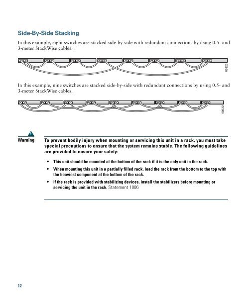
Side-By-Side Stacking<br />
In this example, eight switches are stacked side-by-side with redundant connections by using 0.5- and<br />
3-meter StackWise cables.<br />
In this example, nine switches are stacked side-by-side with redundant connections by using 0.5- and<br />
3-meter StackWise cables.<br />
90532<br />
86825<br />
Warning<br />
To prevent bodily injury when mounting or servicing this unit in a rack, you must take<br />
special precautions to ensure that the system remains stable. The following guidelines<br />
are provided to ensure your safety:<br />
• This unit should be mounted at the bottom of the rack if it is the only unit in the rack.<br />
• When mounting this unit in a partially filled rack, load the rack from the bottom to the top with<br />
the heaviest component at the bottom of the rack.<br />
• If the rack is provided with stabilizing devices, install the stabilizers before mounting or<br />
servicing the unit in the rack. Statement 1006<br />
12


