Catalyst 3750 Switch Getting Started Guide - Cisco
Catalyst 3750 Switch Getting Started Guide - Cisco
Catalyst 3750 Switch Getting Started Guide - Cisco

Create successful ePaper yourself
Turn your PDF publications into a flip-book with our unique Google optimized e-Paper software.
GETTING STARTED GUIDE<br />
<strong>Catalyst</strong> <strong>3750</strong> <strong>Switch</strong> <strong>Getting</strong> <strong>Started</strong> <strong>Guide</strong><br />
1 About this <strong>Guide</strong><br />
2 Taking Out What You Need<br />
3 Running Express Setup<br />
4 Managing the <strong>Switch</strong><br />
5 Planning <strong>Switch</strong> Stacks<br />
6 Rack-Mounting<br />
7 In Case of Difficulty<br />
8 Obtaining Documentation, Obtaining Support, and Security <strong>Guide</strong>lines<br />
9 <strong>Cisco</strong> Warranty Information
1 About this <strong>Guide</strong><br />
This guide provides instructions on how to use Express Setup to initially configure your <strong>Catalyst</strong><br />
switch. Also covered are switch management options, basic rack-mounting procedures, stacking<br />
procedures, port and module connection procedures, power connection procedures, and<br />
troubleshooting help.<br />
For additional installation and configuration information for <strong>Catalyst</strong> <strong>3750</strong> switches, see the<br />
<strong>Catalyst</strong> <strong>3750</strong> documentation on <strong>Cisco</strong>.com. For system requirements, important notes, limitations,<br />
open and resolved bugs, and last-minute documentation updates, see the release notes, also on<br />
<strong>Cisco</strong>.com.<br />
When using the online publications, refer to the documents that match the <strong>Cisco</strong> IOS software version<br />
running on the switch. The software version is on the <strong>Cisco</strong> IOS label on the switch rear panel.<br />
For translations of the warnings that appear in this publication, see the Regulatory Compliance and<br />
Safety Information for the <strong>Catalyst</strong> <strong>3750</strong> <strong>Switch</strong> that accompanies this guide.<br />
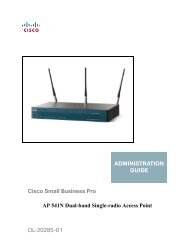
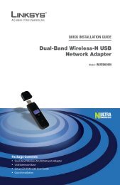
2 Taking Out What You Need<br />
Follow these steps:<br />
1. Unpack and remove the switch and the accessory kit from the shipping box.<br />
2. Return the packing material to the shipping container, and save it for future use.<br />
3. Verify that you have received the items shown on page 3. If any item is missing or damaged,<br />
contact your <strong>Cisco</strong> representative or reseller for instructions. Some switch models might include<br />
additional items that are not shown on page 3.<br />
Note<br />
If you do not specify the length of the StackWise cable, the 0.5-meter cable is supplied.<br />
Equipment That You Supply to Run Express Setup<br />
You need to supply this equipment to run Express Setup:<br />
• PC<br />
• Ethernet (Category 5) straight-through cable (as shown)<br />
2
MASTR<br />
STAT<br />
DUPLX<br />
SPEED<br />
STACK<br />
MODE<br />
1X<br />
2X<br />
15X 17X<br />
16X 18X<br />
31X<br />
3X<br />
32X 34X<br />
47X<br />
48X<br />
<strong>Catalyst</strong> <strong>3750</strong>G SERIES<br />
49<br />
50<br />
51<br />
52<br />
Shipping Box Contents<br />
1 2 3 4 5 6 7 8 9 10 11 12 13 14 15 16<br />
SYST<br />
RPS<br />
17 18 19 20 21 22 23 24 25 26 27 28 29 30 31 32<br />
33 34 35 36 37 38 39 40 41 42 43 44 45 46 47 48<br />
<strong>Catalyst</strong> <strong>3750</strong> switch<br />
Two 19-inch<br />
mounting brackets<br />
Four number-12 Phillips machine screws<br />
0.5-meter, 1.0-meter or 3.0-meter<br />
StackWise cable<br />
Four number-8 Phillips truss-head screws<br />
Six number-8 Phillips flat-head screws<br />
Console cable<br />
(optional)<br />
Connector cover for redundant<br />
power system (RPS)<br />
Two number-4 pan-head screws<br />
AC power cord<br />
Cable guide<br />
One black Phillips machine screw<br />
Product<br />
Documentation<br />
and Compliance<br />
Documentation<br />
Four rubber mounting feet<br />
207383<br />
3
3 Running Express Setup<br />
When you first set up the switch, you should use Express Setup to enter the initial IP information. This<br />
enables the switch to connect to local routers and the Internet. You can then access the switch through<br />
the IP address for further configuration.<br />
To run Express Setup:<br />
Step 1<br />
Step 2<br />
Step 3<br />
Step 4<br />
Step 5<br />
Step 6<br />
Make sure that nothing is connected to the switch.<br />
During Express Setup, the switch acts as a DHCP server. If your PC has a static IP address,<br />
change your PC settings before you begin to temporarily use DHCP.<br />
Power the switch by connecting the supplied AC power cord to the switch power<br />
connector and to a grounded AC outlet.<br />
When the switch powers on, it begins the power-on self-test (POST). During POST, the<br />
LEDs blink while tests verify that the switch functions properly.<br />
Wait for the switch to complete POST, which can take several minutes.<br />
Verify that POST has completed by confirming that the SYST LED remains green. If the<br />
switch fails POST, the SYST LED turns amber.<br />
POST errors are usually fatal. Contact your <strong>Cisco</strong> technical support representative if your<br />
switch fails POST.<br />
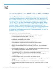
Press and hold the Mode button for<br />
3 seconds. When all of the LEDs left<br />
of the Mode button turn green,<br />
release the Mode button.<br />
If the LEDs left of the Mode button<br />
begin to blink after you press the<br />
button, release it. Blinking LEDs<br />
mean that the switch has already<br />
been configured and cannot go into<br />
Express Setup mode. For more<br />
information, see the “Resetting the<br />
<strong>Switch</strong>” section.<br />
Verify that the switch is in Express Setup mode by confirming that all LEDs left of the<br />
Mode button are green. (On some models, the RPS and PoE LEDs remain off.)<br />
MODE<br />
SYST<br />
RPS<br />
STAT<br />
DUPLX<br />
SPEED<br />
PoE<br />
Mode button<br />
1X<br />
2X<br />
1 2 3 4 5 6 7 8 9 10 11 12 13 14 15 16<br />
15X<br />
16X<br />
4
MODE<br />
SYST<br />
RPS<br />
MASTR<br />
STAT<br />
DUPLX<br />
SP ED<br />
STACK<br />
1X<br />
2X<br />
15X 17X<br />
16X 18X<br />
31X 3X<br />
32X 34X<br />
47X<br />
48X<br />
49<br />
50<br />
51<br />
52<br />
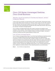
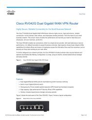
Step 7<br />
Connect a Category 5 Ethernet cable<br />
to any 10/100 or 10/100/1000<br />
Ethernet port on the switch front<br />
panel.<br />
Connect the other end of the cable to<br />
the Ethernet port on your PC.<br />
1 2 3 4 5 6 7 8 9 10 1 12 13 14 15 16<br />
17 18 19 20 21 2 23 24 25 26 27 28 29 30 31 32<br />
3 34 35 36 37 38 39 40 41 42 43 4 45 46 47 48<br />
<strong>Catalyst</strong> 3560G SERIES PoE-48<br />
DHCP-enabled PC<br />
Step 8<br />
Step 9<br />
Verify that the switch and PC Ethernet ports LEDs are green.<br />
Wait 30 seconds.<br />
Start a web browser on your PC.<br />
Enter the IP address 10.0.0.1 in the<br />
web browser, and press Enter.<br />
Step 10<br />
The Express Setup page appears. If it does not appear, see the “In Case of Difficulty”<br />
section for help.<br />
5
Step 11<br />
Step 12<br />
Step 13<br />
Enter this information in the Network Settings fields:<br />
• In the Management Interface (VLAN ID) field, the default is 1. Enter a new VLAN ID<br />
only if you want to change the management interface through which you manage the<br />
switch. The VLAN ID range is 1 to 1001.<br />
• In the IP Address field, enter the IP address of the switch. In the IP Subnet Mask field,<br />
click the drop-down arrow, and select an IP Subnet Mask.<br />
• In the Default Gateway field, enter the IP address for the default gateway (router).<br />
• Enter your password in the <strong>Switch</strong> Password field. The password can be from 1 to 25<br />
alphanumeric characters, can start with a number, is case sensitive, allows embedded<br />
spaces, but does not allow spaces at the beginning or end. In the Confirm <strong>Switch</strong><br />
Password field, enter your password again.<br />
(Optional) You can enter the Optional Settings information now or enter it later by using<br />
the device manager interface:<br />
• In the Host Name field, enter a name for the switch. The host name is limited to 31<br />
characters. Embedded spaces are not allowed.<br />
• Enter the date, time, and time zone information in the System Date, System Time, and<br />
Time Zone fields. Click Enable to enable daylight saving time.<br />
(Optional) Click the Advanced Settings tab on the Express Setup window, and enter the<br />
advanced settings now or enter them later by using the device manager interface.<br />
6
Step 14<br />
Step 15<br />
(Optional) Enter this information in the Advanced Setting fields:<br />
• In the Telnet Access field, click Enable if you are going to use Telnet to manage the<br />
switch by using the command-line interface (CLI). If you enable Telnet access, you<br />
must enter a Telnet password.<br />
• In the Telnet Password field, enter a password. The Telnet password can be from 1 to<br />
25 alphanumeric characters, is case sensitive, allows embedded spaces, but does not<br />
allow spaces at the beginning or end. In the Confirm Telnet Password field, re-enter<br />
the Telnet password.<br />
• In the SNMP field, click Enable to enable Simple Network Management Protocol<br />
(SNMP). Enable SNMP only if you plan to manage switches by using<br />
<strong>Cisco</strong>Works 2000 or another SNMP-based network-management system.<br />
• If you enable SNMP, you must enter a community string in the SNMP Read<br />
Community field, the SNMP Write Community field, or both. SNMP community<br />
strings authenticate access to MIB objects. Embedded spaces are not allowed in SNMP<br />
community strings. When you set the SNMP read community, you can access SNMP<br />
information, but you cannot modify it. When you set the SNMP write community, you<br />
can both access and modify SNMP information.<br />
• In the System Contact and System Location fields, enter a contact name and the wiring<br />
closet, floor, or building where the switch is located.<br />
(Optional) You can enable Internet Protocol version 6 (IPv6) on the switch. From the<br />
Advanced Settings tab, check the Enable IPv6 check box.<br />
Note<br />
Enabling IPv6 restarts the switch when you complete Express Setup.<br />
Step 16<br />
Step 17<br />
To complete Express Setup, click Submit from the Basic Settings or the Advanced Settings<br />
tab to save your settings, or click Cancel to clear your settings.<br />
When you click Submit, the switch is configured and exits Express Setup mode. The PC<br />
displays a warning message and tries to connect with the new switch IP address. If you<br />
configured the switch with an IP address that is in a different subnet from the PC,<br />
connectivity between the PC and the switch is lost.<br />
Disconnect the switch from the PC, and install the switch in your production network. See<br />
the “Managing the <strong>Switch</strong>” section for information about configuring and managing the<br />
switch.<br />
If you need to rerun Express Setup, see the “Resetting the <strong>Switch</strong>” section.<br />
7
Refreshing the PC IP Address<br />
After you complete Express Setup, you should refresh the PC IP address:<br />
• For a dynamically assigned IP address, disconnect the PC from the switch, and reconnect the PC<br />
to the network. The network DHCP server assigns a new IP address to the PC.<br />
• For a statically assigned IP address, change it to the previously configured IP address.<br />
4 Managing the <strong>Switch</strong><br />
After you complete Express Setup and install the switch in your network, use the device manager or<br />
other management options described in this section for further configuration.<br />
Using the Device Manager<br />
The simplest way to manage the switch is by using the device manager that is in the switch memory.<br />
This is an easy-to-use web interface that offers quick configuration and monitoring. You can access<br />
the device manager from anywhere in your network through a web browser.<br />
Follow these steps:<br />
1. Launch a web browser on your PC or workstation.<br />
2. Enter the switch IP address in the web browser, and press Enter. The device manager page appears.<br />
3. Use the device manager to perform basic switch configuration and monitoring. Refer to the device<br />
manager online help for more information.<br />
4. For more advanced configuration, download and run the <strong>Cisco</strong> Network Assistant, which is<br />
described in the next section.<br />
Downloading <strong>Cisco</strong> Network Assistant<br />
<strong>Cisco</strong> Network Assistant is a software program that you download from <strong>Cisco</strong>.com and run on<br />
your PC. It offers advanced options for configuring and monitoring multiple devices, including<br />
switches, switch clusters, switch stacks, routers, and access points. Network Assistant is free—there is<br />
no charge to download, install, or use it.<br />
Follow these steps:<br />
1. Go to this Web address: http://www.cisco.com/go/NetworkAssistant.<br />
You must be a registered <strong>Cisco</strong>.com user, but you need no other access privileges.<br />
2. Find the Network Assistant installer.<br />
8
3. Download the Network Assistant installer, and run it. (You can run it directly from the Web if<br />
your browser offers this choice.)<br />
4. When you run the installer, follow the displayed instructions. In the final panel, click Finish to<br />
complete the Network Assistant installation.<br />
Refer to the Network Assistant online help and the getting started guide for more information.<br />
Command-Line Interface<br />
You can enter <strong>Cisco</strong> IOS commands and parameters through the CLI. Access the CLI either by<br />
connecting your PC directly to the switch console port or through a Telnet session from a remote PC<br />
or workstation.<br />
Follow these steps:<br />
1. Connect the supplied RJ-45-to DB-9 adapter cable to the standard 9-pin serial port on the PC.<br />
Connect the other end of the cable to the console port on the switch.<br />
2. Start a terminal-emulation program on the PC.<br />
3. Configure the PC terminal emulation software for:<br />
– 9600 baud<br />
– 8 data bits<br />
– no parity<br />
– 1 stop bit<br />
– no flow control<br />
4. Use the CLI to enter commands to configure the switch. See the software configuration guide and<br />
the command reference for more information.<br />
Other Management Options<br />
You can use SNMP management applications such as <strong>Cisco</strong>Works Small Network Management<br />
Solution (SNMS) and HP OpenView to configure and manage the switch. You also can manage it<br />
from an SNMP-compatible workstation that is running platforms such as HP OpenView or<br />
SunNet Manager.<br />
The <strong>Cisco</strong> IE2100 Series Configuration Registrar is a network management device that works with<br />
embedded <strong>Cisco</strong> Networking Services (CNS) agents in the switch software. You can use IE2100 to<br />
automate initial configurations and configuration updates on the switch.<br />
See the “Accessing Help Online” section on page 23 for a list of supporting documentation.<br />
9
5 Planning <strong>Switch</strong> Stacks<br />
Before connecting the <strong>Catalyst</strong> <strong>3750</strong> switches in a stack, keep in mind these planning considerations:<br />
• The size of the switch. See the“Technical Specifications” appendix of the <strong>Catalyst</strong> <strong>3750</strong> <strong>Switch</strong><br />
Hardware Installation <strong>Guide</strong> for the switch dimensions. Stacking together switches of the same<br />
size makes it easier to cable the switches.<br />
• Length of cable. Depending on the configuration of your switch stack, you might need different<br />
sized cables. If you don’t specify the length of the StackWise cable, the 0.5-meter cable is supplied.<br />
If you require the 1-meter cable or 3-meter cable, you can order it from your <strong>Cisco</strong> supplier. For<br />
cable numbers, see the <strong>Catalyst</strong> <strong>3750</strong> <strong>Switch</strong> Hardware Installation <strong>Guide</strong>.<br />
Note<br />
For concepts and procedures to manage switch stacks, refer to the switch software<br />
configuration guide.<br />
Powering Considerations<br />
Consider the following guidelines before you power the switches in a stack:<br />
• The sequence in which the switches are<br />
initially powered on might affect the switch<br />
that becomes the stack master.<br />
• If you want a particular switch to become the<br />
stack master, power on that switch first. This<br />
switch becomes the stack master and remains<br />
the stack master until a master re-election is<br />
required. After 20 seconds, power on the<br />
remaining switches in the stack.<br />
• If you have no preference for which switch<br />
becomes the stack master, power on all the<br />
switches in the stack within a 20-second<br />
timeframe. These switches participate in the<br />
stack master election. <strong>Switch</strong>es powered on<br />
after the 20-second timeframe do not<br />
participate in the election.<br />
• Power off a switch before you add it to or<br />
remove it from an existing switch stack.<br />
Note<br />
Stack master elections occur over a 10-second timeframe on switches running releases earlier<br />
than <strong>Cisco</strong> IOS Release 12.2(20)SE3.<br />
For more information on stack master elections, see the “Managing <strong>Switch</strong> Stacks” chapter<br />
in the switch software configuration guide.<br />
10
Cabling Considerations<br />
These illustrations show the recommended <strong>Catalyst</strong> <strong>3750</strong> switch stack configurations with redundant<br />
StackWise cabling connections for optimized stack bandwidth. For more configuration examples, see<br />
the <strong>Catalyst</strong> <strong>3750</strong> <strong>Switch</strong> Hardware Installation <strong>Guide</strong> on <strong>Cisco</strong>.com.<br />
Vertical Stacking<br />
In this example, the stack uses the 0.5-meter StackWise cable to make redundant connections.<br />
In this example, the stacks use both 0.5- and 3-meter StackWise cables to make redundant connections.<br />
86585<br />
86586<br />
11
Side-By-Side Stacking<br />
In this example, eight switches are stacked side-by-side with redundant connections by using 0.5- and<br />
3-meter StackWise cables.<br />
In this example, nine switches are stacked side-by-side with redundant connections by using 0.5- and<br />
3-meter StackWise cables.<br />
90532<br />
86825<br />
Warning<br />
To prevent bodily injury when mounting or servicing this unit in a rack, you must take<br />
special precautions to ensure that the system remains stable. The following guidelines<br />
are provided to ensure your safety:<br />
• This unit should be mounted at the bottom of the rack if it is the only unit in the rack.<br />
• When mounting this unit in a partially filled rack, load the rack from the bottom to the top with<br />
the heaviest component at the bottom of the rack.<br />
• If the rack is provided with stabilizing devices, install the stabilizers before mounting or<br />
servicing the unit in the rack. Statement 1006<br />
12
6 Rack-Mounting<br />
This section covers basic 19-inch rack-mounting and switch port connections. As an example, all the<br />
illustrations show the <strong>Catalyst</strong> <strong>3750</strong>G-48TS switch. You can install and connect other <strong>Catalyst</strong> <strong>3750</strong><br />
switches as shown in these illustrations. For alternate mounting procedures, such as installing the<br />
switch in a 24-inch rack or on a wall, and for additional cabling information, see the <strong>Catalyst</strong> <strong>3750</strong><br />
<strong>Switch</strong> Hardware Installation <strong>Guide</strong> on <strong>Cisco</strong>.com.<br />
Equipment That You Supply<br />
You need to supply a number-2 Phillips screwdriver to rack-mount the switch.<br />
Before You Begin<br />
When determining where to install the switch, verify that these guidelines are met:<br />
• Airflow around the switch and through the<br />
vents is unrestricted.<br />
• Temperature around the switch does not<br />
exceed 113°F (45°C).<br />
• Humidity around the switch does not exceed<br />
85 percent.<br />
• Altitude at the installation site is not greater<br />
than 10,000 feet.<br />
• Clearance to the switch front and rear panels<br />
meets these conditions:<br />
– Front-panel LEDs can be easily read.<br />
– Access to ports is sufficient for<br />
unrestricted cabling.<br />
– AC power cord can reach from the<br />
AC power outlet to the connector on the<br />
switch rear panel.<br />
– Access to the rear of the rack is sufficient<br />
for connecting StackWise cables to<br />
stacked switches.<br />
• Cabling is away from sources of electrical<br />
noise, such as radios, power lines, and<br />
fluorescent lighting fixtures.<br />
• For 10/100 ports and 10/100/1000 ports, the<br />
cable length from a switch to an attached<br />
device cannot exceed 328 feet (100 meters).<br />
• For cable lengths for small form-factor<br />
pluggable (SFP) modules, see the<br />
documentation that shipped with the module.<br />
• For cable lengths for XENPAK modules, see<br />
the documentation that shipped with the<br />
module.<br />
13
Installation Warning Statements<br />
This section includes the basic installation warning statements. Translations of these warning<br />
statements appear in the Regulatory Compliance and Safety Information for the <strong>Catalyst</strong> <strong>3750</strong> <strong>Switch</strong><br />
guide.<br />
Warning<br />
Only trained and qualified personnel should be allowed to install, replace, or service this<br />
equipment. Statement 148<br />
Warning<br />
To prevent the switch from overheating, do not operate it in an area that exceeds the<br />
maximum recommended ambient temperature of 113°F (45°C). To prevent airflow<br />
restriction, allow at least 3 inches (7.6 cm) of clearance around the ventilation openings.<br />
Statement 17B<br />
Warning<br />
Installation of the equipment must comply with local and national electrical codes.<br />
Statement 1074<br />
Warning<br />
To prevent bodily injury when mounting or servicing this unit in a rack, you must take<br />
special precautions to ensure that the system remains stable. The following guidelines<br />
are provided to ensure your safety:<br />
• This unit should be mounted at the bottom of the rack if it is the only unit in the rack.<br />
• When mounting this unit in a partially filled rack, load the rack from the bottom to the top with<br />
the heaviest component at the bottom of the rack.<br />
• If the rack is provided with stabilizing devices, install the stabilizers before mounting or<br />
servicing the unit in the rack. Statement 1006<br />
Warning<br />
This equipment is intended to be grounded. Ensure that the host is connected to earth<br />
ground during normal use. Statement 39<br />
14
Warning<br />
If a redundant power system (RPS) is not connected to the switch, install an RPS<br />
connector cover on the back of the switch. Statement 265<br />
Warning Class 1 laser product. Statement 1008<br />
Warning<br />
For connections outside the building where the equipment is installed, the following<br />
ports must be connected through an approved network termination unit with integral<br />
circuit protection: 10/100/1000 Ethernet. Statement 1044<br />
Warning<br />
Voltages that present a shock hazard may exist on Power over Ethernet (PoE) circuits if<br />
interconnections are made using uninsulated exposed metal contacts, conductors, or<br />
terminals. Avoid using such interconnection methods, unless the exposed metal parts<br />
are located within a restricted access location and users and service people who are<br />
authorized within the restricted access location are made aware of the hazard. A<br />
restricted access area can be accessed only through the use of a special tool, lock and<br />
key or other means of security. Statement 1072<br />
15
SYST<br />
MASTR<br />
STAT<br />
DUPLX<br />
SPEED<br />
MODE<br />
1X<br />
2X<br />
SYST<br />
MASTR<br />
STAT<br />
DUPLX<br />
SPEED<br />
MODE<br />
1X<br />
2X<br />
15X 17X<br />
16X 18X<br />
15X 17X<br />
16X 18X<br />
31X<br />
3X<br />
32X 34X<br />
31X<br />
3X<br />
32X 34X<br />
47X<br />
48X<br />
<strong>Catalyst</strong> <strong>3750</strong>G SERIES<br />
DC INPUTS FOR REMOTE<br />
POWER SUPPLY<br />
SPECIFIED IN MANUAL<br />
47X<br />
48X<br />
<strong>Catalyst</strong> <strong>3750</strong>G SERIES<br />
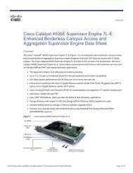
Attaching the Brackets<br />
Use four Phillips flat-head screws to attach the long side of the brackets to <strong>Catalyst</strong> <strong>3750</strong> switches in<br />
one of three mounting positions.<br />
1 2 3 4 5 6 7 8 9 10 11 12 13 14 15 16<br />
RPS<br />
17 18 19 20 21 22 23 24 25 26 27 28 29 30 31 32<br />
STACK<br />
33 34 35 36 37 38 39 40 41 42 43 44 45 46 47 48<br />
49<br />
51<br />
50<br />
52<br />
Front-mounting position<br />
Number-8 Phillips<br />
flat-head screws<br />
1 2 3 4 5 6 7 8 9 10 11 12 13 14 15 16<br />
RPS<br />
17 18 19 20 21 22 23 24 25 26 27 28 29 30 31 32<br />
STACK<br />
33 34 35 36 37 38 39 40 41 42 43 44 45 46 47 48<br />
49<br />
51<br />
50<br />
52<br />
Mid-rack-mounting position (telco rack)<br />
STACK 1 STACK 2<br />
CONSOLE<br />
Rear-mounting position<br />
16
SYST<br />
RPS<br />
MASTR<br />
STAT<br />
DUPLX<br />
SPEED<br />
STACK<br />
MODE<br />
1X<br />
2X<br />
SYST<br />
RPS<br />
MASTR<br />
STAT<br />
DUPLX<br />
SPEED<br />
STACK<br />
MODE<br />
1X<br />
2X<br />
15X 17X<br />
16X 18X<br />
15X 17X<br />
16X 18X<br />
31X<br />
3X<br />
32X 34X<br />
31X<br />
3X<br />
32X 34X<br />
47X<br />
48X<br />
47X<br />
48X<br />
<strong>Catalyst</strong> <strong>3750</strong>G SERIES<br />
<strong>Catalyst</strong> <strong>3750</strong>G SERIES<br />
DC INPUTS FOR REMOTE<br />
POWER SUPPLY<br />
SPECIFIED IN MANUAL<br />
Rack-Mount the <strong>Switch</strong><br />
Use the black Phillips machine screw to attach the cable guide to the left or right bracket. Use the four<br />
number-12 Phillips machine screws to attach the brackets to the rack.<br />
Cable<br />
guide<br />
1 2 3 4 5 6 7 8 9 10 11 12 13 14 15 16<br />
17 18 19 20 21 22 23 24 25 26 27 28 29 30 31 32<br />
33 34 35 36 37 38 39 40 41 42 43 44 45 46 47 48<br />
49<br />
51<br />
Black Phillips<br />
machine screw<br />
Front-mounting position<br />
50<br />
52<br />
Number-12 Phillips<br />
machine screws<br />
1 2 3 4 5 6 7 8 9 10 11 12 13 14 15 16<br />
17 18 19 20 21 22 23 24 25 26 27 28 29 30 31 32<br />
33 34 35 36 37 38 39 40 41 42 43 44 45 46 47 48<br />
49<br />
51<br />
50<br />
52<br />
Mid-rack-mounting position (telco rack)<br />
STACK 1 STACK 2<br />
CONSOLE<br />
Rear-mounting position<br />
17
Connect the StackWise Cables<br />
Follow these steps to connect the StackWise cable to the StackWise ports:<br />
Step 1<br />
Step 2<br />
Remove the dust covers from the StackWise cables and StackWise ports, and store<br />
them for future use.<br />
Insert one end of the<br />
StackWise cable into the<br />
StackWise port on the back<br />
of the switch.<br />
STACK 1 STACK 2<br />
CONSOLE<br />
Step 3<br />
Step 4<br />
Use the window in the StackWise cable to align the connector correctly. Secure<br />
the screws tightly.<br />
Insert the other end of the cable into the connector of the other switch, and secure<br />
the screws tightly.<br />
Caution<br />
Removing and installing the StackWise cable can shorten its useful life. Do not remove<br />
and insert the cable more often than is absolutely necessary.<br />
Note<br />
Always use a <strong>Cisco</strong>-approved StackWise cable to connect the switches.<br />
18
Connect to the <strong>Switch</strong> Ports<br />
This section describes how to connect to the fixed switch ports, the SFP module ports, and the<br />
XENPAK module ports.<br />
Connect to 10/100 and 10/100/1000 Ports<br />
Follow these steps:<br />
Step 1<br />
Step 2<br />
When you connect to servers,<br />
workstations, IP phones, wireless<br />
access points, and routers, insert a<br />
straight-through, twisted four-pair,<br />
Category 5 cable in a switch 10/100 or<br />
10/100/1000 port.<br />
Use a crossover, twisted four-pair,<br />
Category 5 cable when you connect to<br />
other switches, hubs, or repeaters.<br />
Insert the other cable end into an RJ-45 connector on the other device.<br />
MODE<br />
SYST<br />
RPS<br />
MASTR<br />
STAT<br />
DUPLX<br />
SPEED<br />
STACK<br />
1X<br />
2X<br />
4 3 15 16<br />
10/100 or 10/100/1000 ports<br />
15X<br />
16X<br />
The fixed ports on the <strong>Catalyst</strong> <strong>3750</strong> Power over Ethernet (PoE) switches provide PoE support for<br />
devices that are compliant with IEEE 802.3af, and also provide <strong>Cisco</strong> pre-standard PoE support for<br />
<strong>Cisco</strong> IP Phones and <strong>Cisco</strong> Aironet Access Points.<br />
Each of the <strong>Catalyst</strong> <strong>3750</strong>-24PS switch 10/100 ports or the <strong>Catalyst</strong> <strong>3750</strong>G-24PS switch<br />
10/100/1000 ports can deliver up to 15.4 W of PoE. On the <strong>Catalyst</strong> <strong>3750</strong>-48PS or <strong>3750</strong>G-48PS<br />
switches, any 24 of the 48 10/100 or 10/100/1000 ports can deliver 15.4 W of PoE, or any<br />
combination of the ports can deliver an average of 7.7 W of PoE at the same time, up to a maximum<br />
switch power output of 370 W.<br />
By default, a <strong>Catalyst</strong> <strong>3750</strong> switch PoE port automatically provides power when a valid powered<br />
device is connected to it. For information about configuring and monitoring PoE ports, see the switch<br />
software configuration guide. For information about troubleshooting PoE problems, see the<br />
<strong>Catalyst</strong> <strong>3750</strong> <strong>Switch</strong> Hardware Installation <strong>Guide</strong> on <strong>Cisco</strong>.com.<br />
Note<br />
The automatic medium-dependent interface crossover (Auto-MDIX) feature is enabled by<br />
default on switches running <strong>Cisco</strong> IOS Release 12.2(18)SE or later. When the Auto-MDIX<br />
feature is enabled, the switch detects the required cable type for copper Ethernet connections<br />
and configures the interfaces accordingly. Therefore, you can use either a crossover or a<br />
straight-through cable for connections to a copper 10/100, 10/100/1000, or 1000BASE-T SFP<br />
module port on the switch, regardless of the type of device on the other end of the connection.<br />
19
Install the SFP Modules and Connect to the Ports<br />
Follow these steps:<br />
Step 1<br />
Grasp the module on the sides, and<br />
insert it into the switch slot until you<br />
feel the connector snap into place.<br />
13X<br />
13<br />
14 15 16 17 18 19 20 21 22 23 24<br />
<strong>Catalyst</strong> <strong>3750</strong>G SERIES PoE-24<br />
23X<br />
14X<br />
25<br />
27<br />
SFP module<br />
24X<br />
26<br />
28<br />
Step 2<br />
Insert an appropriate cable into the<br />
module port. Insert the other cable<br />
end into the other device.<br />
13X<br />
13<br />
14 15 16 17 18 19 20 21 22 23 24<br />
<strong>Catalyst</strong> <strong>3750</strong>G SERIES PoE-24<br />
23X<br />
14X<br />
25<br />
27<br />
24X<br />
26<br />
28<br />
SFP module port<br />
For a list of supported modules, see the release notes on <strong>Cisco</strong>.com. For detailed instructions on<br />
installing, removing, and connecting to SFP modules, see the documentation that came with the<br />
SFP module.<br />
Caution<br />
Removing and installing an SFP module can shorten its useful life. Do not remove and<br />
insert SFP modules more often than is absolutely necessary.<br />
Verify Port Connectivity<br />
After you connect to the switch port, the port LED turns amber while the switch establishes a link.<br />
This process takes about 30 seconds. Then the LED turns green when the switch and the target device<br />
have an established link. If the LED is off, the target device might not be turned on, there might be a<br />
cable problem, or there might be a problem with the adapter installed in the target device. See the “In<br />
Case of Difficulty” section on page 22 for information about online assistance.<br />
20
Install the XENPAK Module and Connect to the Ports<br />
Follow these steps to install a XENPAK module into the XENPAK module slot on the front panel of the<br />
<strong>Catalyst</strong> <strong>3750</strong>G-16TD switch:<br />
Step 1<br />
Remove the two Phillips-head<br />
retaining screws from the XENPAK<br />
module slot cover, and store them for<br />
later use. Remove the cover.<br />
1<br />
<strong>Catalyst</strong> <strong>3750</strong> series<br />
Step 2<br />
Align the XENPAK module with the<br />
guide rails inside the module slot,<br />
and slide the module into the slot<br />
until the XENPAK faceplate is flush<br />
with the switch faceplate.<br />
TX RX<br />
1<br />
<strong>Catalyst</strong> <strong>3750</strong> series<br />
Rubber<br />
plug<br />
XENPAK<br />
module<br />
Step 3<br />
Step 4<br />
Step 5<br />
Secure the XENPAK module in place by tightening the two captive installation<br />
screws. Do not overtighten the screws.<br />
Remove the rubber plugs from the XENPAK module ports and fiber-optic cable, and<br />
store them for future use.<br />
Align the cable SC connector with<br />
the XENPAK module connector, so<br />
that transmit (TX) meets receive<br />
(RX), and RX meets TX.<br />
1<br />
TX RX<br />
<strong>Catalyst</strong> <strong>3750</strong> series<br />
XENPAK<br />
module<br />
See the “Verify Port Connectivity” section on page 20 for instructions on how to verify that the<br />
XENPAK module ports have established a link to the external device.<br />
21
7 In Case of Difficulty<br />
If you experience difficulty, help is available in this section and also on <strong>Cisco</strong>.com. This section<br />
includes Express Setup troubleshooting, how to reset the switch, how to access help online, and where<br />
to find more information.<br />
Troubleshooting Express Setup<br />
If Express Setup does not run, or if the Express Setup page does not appear in your browser:<br />
• Did you verify that POST successfully ran<br />
before starting Express Setup<br />
• Did you press the Mode button while the<br />
switch was still running POST<br />
• Did you try to continue without confirming<br />
that the switch was in Express Setup mode<br />
If not, make sure that only the SYST and STAT<br />
LEDs are green before pressing the Mode button<br />
to enter the Express Setup mode.<br />
If yes, wait until POST completes. Power cycle the<br />
switch. Wait until POST completes. Confirm that<br />
the SYST and STAT LEDs are green. Press the<br />
Mode button to enter Express Setup mode.<br />
Verify that all LEDs above the Mode button are<br />
green. (The RPS LED is off.) If necessary, press<br />
the Mode button to enter Express Setup mode.<br />
• Does your PC have a static IP address If yes, before connecting to the switch, change<br />
your PC settings to temporarily use DHCP.<br />
• Did you connect a crossover cable instead of<br />
a straight-through Ethernet cable between a<br />
switch port and the Ethernet port of the PC<br />
If yes, connect a straight-through cable to an<br />
Ethernet port on the switch and the PC. Wait 30<br />
seconds before you enter 10.0.0.1 in the browser.<br />
• Did you connect the Ethernet cable to the<br />
console port instead of to a 10/100 or<br />
10/100/1000 Ethernet port on the switch<br />
If yes, disconnect the cable from the console port.<br />
Then connect the cable to an Ethernet port on the<br />
switch and the PC. Wait 30 seconds before you<br />
enter 10.0.0.1 in the browser.<br />
22
• Did you wait 30 seconds after you connected<br />
the switch and the PC before you entered the<br />
IP address in your browser<br />
• Did you enter the wrong address in the<br />
browser, or is there an error message<br />
If not, wait 30 seconds, re-enter 10.0.0.1 in the<br />
browser, and press Enter.<br />
If yes, re-enter 10.0.0.1 in the browser, and press<br />
Enter.<br />
Resetting the <strong>Switch</strong><br />
This section describes how to reset the switch by rerunning Express Setup. These are reasons why you<br />
might want to reset the switch:<br />
• You installed the switch in your network and cannot connect to it because you assigned the<br />
incorrect IP address.<br />
• You want to clear all configuration from the switch and assign a new IP address.<br />
• You are trying to enter Express Setup mode, and the switch LEDs start blinking when you press<br />
the Mode button (which means that the switch is already configured with IP information).<br />
Caution<br />
Resetting the switch deletes the configuration and reboots the switch.<br />
To reset the switch:<br />
• Press and hold the Mode button. The switch LEDs begin blinking after about 3 seconds. Continue<br />
holding down the Mode button. The LEDs stop blinking after 7 more seconds, and then the switch<br />
reboots.<br />
The switch now behaves like an unconfigured switch. You can enter the switch IP information by using<br />
Express Setup as described in the “Running Express Setup” section on page 4.<br />
Accessing Help Online<br />
First look for a solution to your problem in the troubleshooting section of the hardware installation<br />
guide or the software configuration guide on <strong>Cisco</strong>.com. You can also access the <strong>Cisco</strong> Technical<br />
Support and Documentation website for a list of known hardware problems and extensive<br />
troubleshooting documentation.<br />
23
For More Information<br />
For more information about the switch, see these documents on <strong>Cisco</strong>.com:<br />
• <strong>Catalyst</strong> <strong>3750</strong> <strong>Switch</strong> Hardware Installation <strong>Guide</strong><br />
• Regulatory Compliance and Safety Information for the <strong>Catalyst</strong> <strong>3750</strong> <strong>Switch</strong><br />
• Release Notes for the <strong>Catalyst</strong> <strong>3750</strong>, 3560, and 2960 <strong>Switch</strong>es<br />
• <strong>Catalyst</strong> <strong>3750</strong> <strong>Switch</strong> Software Configuration <strong>Guide</strong><br />
• <strong>Catalyst</strong> <strong>3750</strong> <strong>Switch</strong> Command Reference<br />
• <strong>Catalyst</strong> <strong>3750</strong>, 3560, 2975, 2970, and 2960 <strong>Switch</strong> System Message <strong>Guide</strong><br />
8 Obtaining Documentation, Obtaining Support, and<br />
Security <strong>Guide</strong>lines<br />
For information on obtaining documentation, submitting a service request, and gathering additional<br />
information, see the monthly What’s New in <strong>Cisco</strong> Product Documentation, which also lists all new<br />
and revised <strong>Cisco</strong> technical documentation, at:<br />
http://www.cisco.com/en/US/docs/general/whatsnew4/whatsnew.html<br />
Subscribe to the What’s New in <strong>Cisco</strong> Product Documentation as a Really Simple Syndication (RSS) feed<br />
and set content to be delivered directly to your desktop using a reader application. The RSS feeds are a free<br />
service and <strong>Cisco</strong> currently supports RSS Version 2.0.<br />
9 <strong>Cisco</strong> Warranty Information<br />
For warranty information, see the product documentation and compliance document that shipped<br />
with this product.<br />
24
CCDE, CCENT, CCSI, <strong>Cisco</strong> Eos, <strong>Cisco</strong> Explorer, <strong>Cisco</strong> HealthPresence, <strong>Cisco</strong> IronPort, the <strong>Cisco</strong> logo, <strong>Cisco</strong> Nurse Connect, <strong>Cisco</strong> Pulse, <strong>Cisco</strong> SensorBase,<br />
<strong>Cisco</strong> StackPower, <strong>Cisco</strong> StadiumVision, <strong>Cisco</strong> TelePresence, <strong>Cisco</strong> TrustSec, <strong>Cisco</strong> Unified Computing System, <strong>Cisco</strong> WebEx, DCE, Flip Channels, Flip for<br />
Good, Flip Mino, Flipshare (Design), Flip Ultra, Flip Video, Flip Video (Design), Instant Broadband, and Welcome to the Human Network are trademarks;<br />
Changing the Way We Work, Live, Play, and Learn, <strong>Cisco</strong> Capital, <strong>Cisco</strong> Capital (Design), <strong>Cisco</strong>:Financed (Stylized), <strong>Cisco</strong> Store, Flip Gift Card, and One Million<br />
Acts of Green are service marks; and Access Registrar, Aironet, AllTouch, AsyncOS, Bringing the Meeting To You, <strong>Catalyst</strong>, CCDA, CCDP, CCIE, CCIP, CCNA,<br />
CCNP, CCSP, CCVP, <strong>Cisco</strong>, the <strong>Cisco</strong> Certified Internetwork Expert logo, <strong>Cisco</strong> IOS, <strong>Cisco</strong> Lumin, <strong>Cisco</strong> Nexus, <strong>Cisco</strong> Press, <strong>Cisco</strong> Systems, <strong>Cisco</strong> Systems<br />
Capital, the <strong>Cisco</strong> Systems logo, <strong>Cisco</strong> Unity, Collaboration Without Limitation, Continuum, EtherFast, Ether<strong>Switch</strong>, Event Center, Explorer, Follow Me<br />
Browsing, GainMaker, iLYNX, IOS, iPhone, IronPort, the IronPort logo, Laser Link, LightStream, Linksys, MeetingPlace, MeetingPlace Chime Sound, MGX,<br />
Networkers, Networking Academy, PCNow, PIX, PowerKEY, PowerPanels, PowerTV, PowerTV (Design), PowerVu, Prisma, ProConnect, ROSA, SenderBase,<br />
SMARTnet, Spectrum Expert, StackWise, WebEx, and the WebEx logo are registered trademarks of <strong>Cisco</strong> and/or its affiliates in the United States and certain<br />
other countries.<br />
All other trademarks mentioned in this document or website are the property of their respective owners. The use of the word partner does not imply a partnership<br />
relationship between <strong>Cisco</strong> and any other company. (1002R)<br />
Any Internet Protocol (IP) addresses used in this document are not intended to be actual addresses. Any examples, command display output, and figures included<br />
in the document are shown for illustrative purposes only. Any use of actual IP addresses in illustrative content is unintentional and coincidental.<br />
<strong>Catalyst</strong> <strong>3750</strong> <strong>Switch</strong> <strong>Getting</strong> <strong>Started</strong> <strong>Guide</strong><br />
© 2004-2010 <strong>Cisco</strong> Systems, Inc. All rights reserved.<br />
25
Americas Headquarters<br />
<strong>Cisco</strong> Systems, Inc.<br />
San Jose, CA<br />
Asia Pacific Headquarters<br />
<strong>Cisco</strong> Systems (USA) Pte. Ltd.<br />
Singapore<br />
Europe Headquarters<br />
<strong>Cisco</strong> Systems International BV<br />
Amsterdam, The Netherlands<br />
<strong>Cisco</strong> has more than 200 offices worldwide. Addresses, phone numbers, and fax numbers are listed on the<br />
<strong>Cisco</strong> Website at www.cisco.com/go/offices.<br />
OL-21820-01