

Atmel AT89C52 Data Sheet
Atmel AT89C52 Data Sheet
Atmel AT89C52 Data Sheet

Create successful ePaper yourself
Turn your PDF publications into a flip-book with our unique Google optimized e-Paper software.
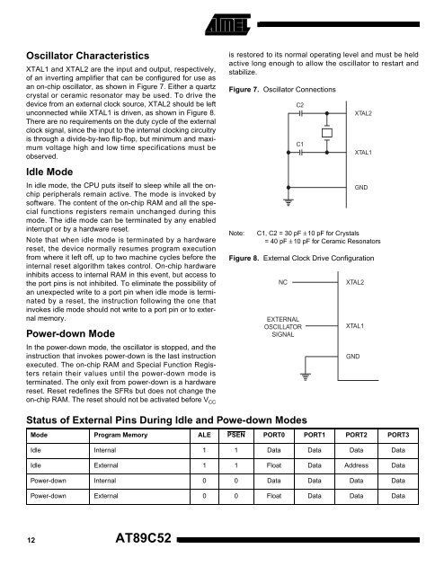
Oscillator Characteristics<br />
XTAL1 and XTAL2 are the input and output, respectively,<br />
of an inverting amplifier that can be configured for use as<br />
an on-chip oscillator, as shown in Figure 7. Either a quartz<br />
crystal or ceramic resonator may be used. To drive the<br />
device from an external clock source, XTAL2 should be left<br />
unconnected while XTAL1 is driven, as shown in Figure 8.<br />
There are no requirements on the duty cycle of the external<br />
clock signal, since the input to the internal clocking circuitry<br />
is through a divide-by-two flip-flop, but minimum and maximum<br />
voltage high and low time specifications must be<br />
observed.<br />
Idle Mode<br />
In idle mode, the CPU puts itself to sleep while all the onchip<br />
peripherals remain active. The mode is invoked by<br />
software. The content of the on-chip RAM and all the special<br />
functions registers remain unchanged during this<br />
mode. The idle mode can be terminated by any enabled<br />
interrupt or by a hardware reset.<br />
Note that when idle mode is terminated by a hardware<br />
reset, the device normally resumes program execution<br />
from where it left off, up to two machine cycles before the<br />
internal reset algorithm takes control. On-chip hardware<br />
inhibits access to internal RAM in this event, but access to<br />
the port pins is not inhibited. To eliminate the possibility of<br />
an unexpected write to a port pin when idle mode is terminated<br />
by a reset, the instruction following the one that<br />
invokes idle mode should not write to a port pin or to external<br />
memory.<br />
Power-down Mode<br />
In the power-down mode, the oscillator is stopped, and the<br />
instruction that invokes power-down is the last instruction<br />
executed. The on-chip RAM and Special Function Registers<br />
retain their values until the power-down mode is<br />
terminated. The only exit from power-down is a hardware<br />
reset. Reset redefines the SFRs but does not change the<br />
on-chip RAM. The reset should not be activated before V CC<br />
is restored to its normal operating level and must be held<br />
active long enough to allow the oscillator to restart and<br />
stabilize.<br />
Figure 7. Oscillator Connections<br />
C2<br />
C1<br />
XTAL2<br />
XTAL1<br />
GND<br />
Note: C1, C2 = 30 pF ± 10 pF for Crystals<br />
= 40 pF ± 10 pF for Ceramic Resonators<br />
Figure 8. External Clock Drive Configuration<br />
NC<br />
EXTERNAL<br />
OSCILLATOR<br />
SIGNAL<br />
XTAL2<br />
XTAL1<br />
GND<br />
Status of External Pins During Idle and Powe-down Modes<br />
Mode Program Memory ALE PSEN PORT0 PORT1 PORT2 PORT3<br />
Idle Internal 1 1 <strong>Data</strong> <strong>Data</strong> <strong>Data</strong> <strong>Data</strong><br />
Idle External 1 1 Float <strong>Data</strong> Address <strong>Data</strong><br />
Power-down Internal 0 0 <strong>Data</strong> <strong>Data</strong> <strong>Data</strong> <strong>Data</strong><br />
Power-down External 0 0 Float <strong>Data</strong> <strong>Data</strong> <strong>Data</strong><br />
12<br />
<strong>AT89C52</strong>


