MACH 130 FP Mains Voltage 230V / 120V - Dr. Mach
MACH 130 FP Mains Voltage 230V / 120V - Dr. Mach
MACH 130 FP Mains Voltage 230V / 120V - Dr. Mach

You also want an ePaper? Increase the reach of your titles
YUMPU automatically turns print PDFs into web optimized ePapers that Google loves.
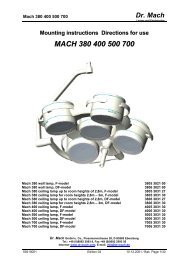
<strong>MACH</strong> <strong>130</strong> <strong>FP</strong> Wall model<br />
Directions for use<br />
<strong>MACH</strong> <strong>130</strong> <strong>FP</strong><br />
<strong>Mains</strong> voltage <strong>230V</strong> / <strong>120V</strong><br />
<strong>Dr</strong>. <strong>Mach</strong><br />
Lamps and Engineering<br />
<strong>Mach</strong> <strong>130</strong> <strong>FP</strong> – <strong>230V</strong>/<strong>120V</strong> wall lamp.........................................Order No. <strong>130</strong>2302140<br />
<strong>Dr</strong>. <strong>Mach</strong> GmbH u. Co., Flossmannstrasse 28, D-85560 Ebersberg<br />
Tel.: +49 (0)8092 2093 0, Fax +49 (0)8092 2093 50<br />
Internet: www.dr-mach.com, E-mail: info@dr-mach.de<br />
59100002 Edition 07 05.06.2002 / Bak Page 1/25
<strong>MACH</strong> <strong>130</strong> <strong>FP</strong> Wall model<br />
List of contents<br />
<strong>Dr</strong>. <strong>Mach</strong><br />
Lamps and Engineering<br />
1. Safety instructions ............................................................................................ Page 3<br />
2. Mounting layout wall attachment ...................................................................... Page 4<br />
3. Mounting the spring arm and the lamp ............................................................. Page 5<br />
3.1 Mounting the spring arm............................................................................. Page 5<br />
3.2 Removing the spring arm............................................................................ Page 5<br />
3.3 Mounting the lamp ...................................................................................... Page 6<br />
4. Operating the lamp <strong>Mach</strong> <strong>130</strong> <strong>FP</strong>..................................................................... Page 7<br />
4.1 ON/OFF switch ........................................................................................... Page 7<br />
4.2 Positioning .................................................................................................. Page 8<br />
4.3 Light field adjustment (focusing)................................................................. Page 8<br />
5. Cleaning............................................................................................................ Page 9<br />
5.1 Sterilizable handle ...................................................................................... Page 9<br />
5.2 Lamp head, protective disk......................................................................... Page 11<br />
6. Maintenance ..................................................................................................... Page 12<br />
6.1 Adjustments at the wall attachment............................................................ Page 12<br />
6.2 Adjustments at the lamp head .................................................................... Page 13<br />
6.3 Changing of spare parts ............................................................................. Page 14<br />
6.3.1 Changing the halogen bulbs.................................................................. Page 14<br />
6.3.2 Changing the fuses (<strong>230V</strong> / <strong>120V</strong>) ........................................................ Page 15<br />
6.3.3 Changing the ON/OFF switch ............................................................... Page 16<br />
6.3.4 Changing the filter disk.......................................................................... Page 17<br />
6.3.5 Changing the protective disk ................................................................. Page 18<br />
7. Data .................................................................................................................. Page 19<br />
7.1 Technical data ............................................................................................ Page 19<br />
7.2 Wiring.......................................................................................................... Page 19<br />
7.3 Environmental conditions............................................................................ Page 20<br />
8. Characteristics.................................................................................................. Page 20<br />
8.1 Specification of bulb ................................................................................... Page 20<br />
8.2 Specification of fuse ................................................................................... Page 21<br />
8.3 CE mark...................................................................................................... Page 21<br />
9. Disposal............................................................................................................ Page 21<br />
10. Spare parts ....................................................................................................... Page 22<br />
10.1 <strong>Mach</strong> <strong>130</strong> <strong>FP</strong> <strong>230V</strong>/<strong>120V</strong> wall model....................................................... Page 22<br />
10.2 Wall attachment........................................................................................ Page 23<br />
10.3 Spare parts list.......................................................................................... Page 24<br />
59100002 Edition 07 05.06.2002 / Bak Page 2/25
<strong>MACH</strong> <strong>130</strong> <strong>FP</strong> Wall model<br />
1. Safety instructions<br />
Please pay attention to the directions for use when handling the lamp.<br />
Attention:<br />
<strong>Dr</strong>. <strong>Mach</strong><br />
Lamps and Engineering<br />
This device is not suitable for use in hazardous locations. The lamp is classified<br />
as a Group 1 device according to the regulations for EEMP.<br />
Repairs to the lamp and special installation work on the reflector or plug-in socket should<br />
only be carried out by ourselves or a company expressly authorised by ourselves.<br />
The manufacturer is only responsible for the safety of the lamp if repairs and alterations have<br />
been carried out by themselves or a company who can guarantee that the safety regulations<br />
have been observed.<br />
The manufacturer is not liable for personal or material damages if the lamp is misappropriately<br />
or incorrectly operated or misused.<br />
The lamp body may only be dismantled from the spring arm in reverse order to its assembly<br />
after the assembly locking device has been inserted and tightened since the arm is under<br />
spring tension.<br />
Make sure that the lamp is in perfect working order before every use.<br />
The lamps <strong>Mach</strong> <strong>130</strong> <strong>FP</strong> may not be used without the dielectric filter disk.<br />
The dielectric filter disk between reflector and protective disk prevents a damaging heating of<br />
the illuminated area.<br />
59100002 Edition 07 05.06.2002 / Bak Page 3/25
<strong>MACH</strong> <strong>130</strong> <strong>FP</strong> Wall model<br />
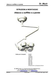
Bracket<br />
2. Mounting layout<br />
Wall attachment<br />
Circlip<br />
Levelling washer (Remark!)<br />
Levelling washer<br />
Spring arm<br />
OT -lamp<br />
<strong>Dr</strong>. <strong>Mach</strong><br />
Lamps and Engineering<br />
Remark:<br />
One levelling washer is always necessary.<br />
If the distance between wall bracket and spring arm is too big, use the second levelling washer.<br />
The circlip (Seegerring) must be easy to mount and has to snap in. It should turn easily in the groove.<br />
59100002 Edition 07 05.06.2002 / Bak Page 4/25
<strong>MACH</strong> <strong>130</strong> <strong>FP</strong> Wall model<br />
3. Mounting the spring arm and the lamp<br />
3.1 Mounting the spring arm<br />
<strong>Dr</strong>. <strong>Mach</strong><br />
Lamps and Engineering<br />
• Unscrew the cover 1 (with sliding contact plug) from the articulated arm.<br />
• Slide the articulated arm from below into the upper articulated arm.<br />
• Slide the levelling washer and safety ring onto the connection tube of the spring arm in the correct order.<br />
• Place the safety ring in position.<br />
Ensure that the safety ring slots properly in the groove of the coupling journal (tool: mounting pliers).<br />
• Place the cover back on the articulated arm and screw tight.<br />
3.2 Removing the spring arm<br />
• Disconnect the electrical connection (in case of direct electrical connection using the fuses).<br />
• Unscrew the cover 1 (with sliding contact plug) from the articulated arm.<br />
• Pull the cover 1 off upwards by lateral compressing.<br />
• Remove the levelling washer and safety ring with the mounting pliers and pull the suspension tube out<br />
in a downwards movement.<br />
59100002 Edition 07 05.06.2002 / Bak Page 5/25<br />
1
<strong>MACH</strong> <strong>130</strong> <strong>FP</strong> Wall model<br />
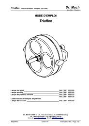
3.3. Mounting the lamp<br />
<strong>Dr</strong>. <strong>Mach</strong><br />
Lamps and Engineering<br />
When mounting the lamp and also at one-yearly intervals, a light coat of acid-free grease should be applied<br />
to the mounting journal and the journal groove F of the lamp, or possibly the already existing cardan bow.<br />
Caution:<br />
The lamp may only be dismounted (in reverse order to the mounting procedure) after the mounting<br />
safeguard has been positioned and screwed tight, as the arm is under spring tension.<br />
Element D<br />
Safeguard bushing<br />
• Loosen locking screw K using a cross screwdriver.<br />
• Disengage spring element D from the safeguard<br />
bushing using a screwdriver (by pushing in direction<br />
of the outer edge) and slide back the<br />
safeguard bushing.<br />
• Take out the segment and remove helmet L.<br />
• Push the lamp and the cardan bow into the bore<br />
of the spring arm, so that journal groove F is<br />
visible in slot E.<br />
• Insert the segment and slide the safeguard<br />
bushing downwards again as far as possible. Insert<br />
locking screw K (including lock washer) and<br />
screw tight.<br />
Then REMOVE MOUNTING SAFEGUARD in the<br />
articulated arm.<br />
• Unscrew cylinder screw H.<br />
• Take out the red safety angle G.<br />
To do so, carefully move the articulated arm<br />
upwards or downwards.<br />
Caution: Hold the arm, to avoid bouncing<br />
up!<br />
The mounting safeguard (called G in all<br />
mounting instructions) and the corresponding<br />
cylinder screw H must be kept carefully for<br />
maintaining and dismounting the lamp.<br />
59100002 Edition 07 05.06.2002 / Bak Page 6/25
<strong>MACH</strong> <strong>130</strong> <strong>FP</strong> Wall model<br />
67,68<br />
4. Operating the lamp <strong>Mach</strong> <strong>130</strong> <strong>FP</strong><br />
<strong>Dr</strong>. <strong>Mach</strong><br />
Lamps and Engineering<br />
Lamp features:<br />
• <strong>Mach</strong> <strong>130</strong> <strong>FP</strong> with focusable light field size and<br />
integrated dielectric filter disk.<br />
The reflector is adapted to the dielectric filter<br />
disk.<br />
The lamp-types mentioned above are available as:<br />
• <strong>Mach</strong> <strong>130</strong> <strong>FP</strong>; mains voltage <strong>230V</strong>/<strong>120V</strong>; integrated<br />
toroid transformer<br />
4.1 ON/OFF switch<br />
The switch 67 (with push button 68) switches the<br />
lamp on and off.<br />
For switching the lamp on and off push button 68.<br />
59100002 Edition 07 05.06.2002 / Bak Page 7/25
<strong>MACH</strong> <strong>130</strong> <strong>FP</strong> Wall model<br />
GL<br />
45<br />
58<br />
44<br />
45<br />
4.2 Positioning<br />
<strong>Dr</strong>. <strong>Mach</strong><br />
Lamps and Engineering<br />
Use the handle or the handle rail GL to position the<br />
lamp.<br />
The lamp is equipped with a handle with sterilizable<br />
handle sleeve 45.<br />
The sterilizable handle sleeve 45 can be removed.<br />
It is fixed by the couple 44 to the handle bar 58.<br />
4.3 Light field adjustment<br />
(focusing) – <strong>Mach</strong> <strong>130</strong> <strong>FP</strong><br />
The lamp models <strong>Mach</strong> <strong>130</strong> <strong>FP</strong> have a focusing<br />
function. That means, you can either enlarge the<br />
diameter of the light field or bundle the light to a<br />
smaller area, depending on the circumstances.<br />
To activate the function of focusing turn the handle<br />
45 (see figure).<br />
59100002 Edition 07 05.06.2002 / Bak Page 8/25
<strong>MACH</strong> <strong>130</strong> <strong>FP</strong> Wall model<br />
V<br />
45<br />
Cleaning / disinfection and sterilisation<br />
5. Cleaning<br />
5.1 Sterilizable handle<br />
<strong>Dr</strong>. <strong>Mach</strong><br />
Lamps and Engineering<br />
The lamps <strong>Mach</strong> <strong>130</strong>/<strong>Mach</strong> <strong>130</strong>F 22,8V UL/Uniflex<br />
R96 <strong>120V</strong> UL can be equipped as an option with a<br />
sterilizable handle 45.<br />
The sterilizable handle 45 is removable and sterilizable.<br />
Before using the first time and before every<br />
use the handle sleeve must be cleaned, disinfected<br />
and sterilised.<br />
The handle sleeve must be removed for sterilisation:<br />
• To remove press the lock V and pull off the<br />
sterilisable handle sleeve 45 while keeping the<br />
lock pressed.<br />
• To attach, push on and slightly twist the handle<br />
until the lock V engages securely.<br />
Handles often become unsterile during an OP;<br />
therefore always keep additional handles available<br />
for exchange.<br />
Basics<br />
Efficient cleaning / disinfection is an essential requirement for effective sterilisation of the handle.<br />
Within the scope of responsibility for the sterility of the products it should be noted that only sufficiently<br />
validated equipment and product specific processes are used for cleaning / disinfection and that the validated<br />
parameters are complied with in every cycle.<br />
In addition, the hospital / clinic hygiene regulations must be observed.<br />
Cleaning / disinfection<br />
Cleaning and disinfection must be carried out immediately after use.<br />
A mechanised process (disinfector) should be used for cleaning / disinfection. The efficiency of the process<br />
used must be recognised and validated in principle (e.g. listed under disinfectants and disinfection procedures<br />
tested and recognised by Robert-Koch-Institute / DGHM).<br />
When using other procedures (e.g. a manual procedure), proof and process efficiency in principle must be<br />
provided within the scope of validation.<br />
Proof in principle of the suitability of the handles for efficient cleaning / disinfection was provided using a<br />
cyclic cleaning system (Netsch-Bellmed T-600-IUDT/AN, programme 2 for small parts; code B).<br />
It is not allowed to use agents / disinfectants, which contain the following substances, as these may cause<br />
changes in the material:<br />
- High-concentration organic and inorganic acids<br />
- Chlorinated hydrocarbons<br />
- 2-ethoxyethanol<br />
59100002 Edition 07 05.06.2002 / Bak Page 9/25
<strong>MACH</strong> <strong>130</strong> <strong>FP</strong> Wall model<br />
When cleaning / disinfecting, the following procedures must be followed:<br />
<strong>Dr</strong>. <strong>Mach</strong><br />
Lamps and Engineering<br />
Process Time (sec.)<br />
Zone 1 Pre-rinse, external, cold, 10 – 15°C 45<br />
Washing, acidic, external 35°C 120<br />
<strong>Dr</strong>aining time 10<br />
Re-rinse, external approx. 80°C *10<br />
<strong>Dr</strong>aining time *15<br />
Re-rinse, external approx. 80°C *15<br />
<strong>Dr</strong>aining time 15<br />
Zone 2 Washing, alkaline, external, 93°C 135<br />
<strong>Dr</strong>aining time 10<br />
Re-rinse, external, acidic, 90°C 10<br />
<strong>Dr</strong>aining time 15<br />
Re-rinse, external 90°C 15<br />
<strong>Dr</strong>aining time 15<br />
Zone 3 <strong>Dr</strong>ying, external 100 – 120°C 200<br />
Zone 4 <strong>Dr</strong>ying, external 100 – 120°C 200<br />
Door open / close & transport 60<br />
(sluice discharge)<br />
Cycle time overall ca. 290<br />
≈ 5 minutes<br />
* When occupying the disinfection zone (washing zone 2), the re-rinse and draining times will depend on<br />
the respective objects being washed therein!<br />
Sterilisation<br />
Only previously cleaned and disinfected handles may be sterilised.<br />
The handles are placed in a suitable sterilisation pack (one-way sterilisation pack, e.g. foil / paper sterilisation<br />
bags, single or double pack) in accordance with DIN EN 868 / ISO 11607 for steam sterilisation and<br />
then sterilised.<br />
Use only the sterilisation procedure listed below for sterilisation. Other sterilisation procedures (e.g. ethylene<br />
oxide, formaldehyde and low-temperature plasma sterilisation) are not permissible.<br />
Steam sterilisation procedure<br />
Validated in accordance with DIN EN 554/ISO 11134<br />
Maximum sterilisation temperature 134°C<br />
Proof in principle of the handles’ suitability for effective sterilisation was provided using a fractional vacuum<br />
process (Euroselectomat 666 by MMM Münchner Medizin Mechanik GmbH, sterilising temperature 134°C,<br />
holding time 7 min.)<br />
Inspection / durability<br />
The handles should be inspected for damage and changed before re-use, if required.<br />
The handles may be cleaned / disinfected, sterilised and re-used for a maximum of 1000 times. If the handles<br />
are re-used more than 1000 times, then this will be the responsibility of the hospital / clinic.<br />
59100002 Edition 07 05.06.2002 / Bak Page 10/25
<strong>MACH</strong> <strong>130</strong> <strong>FP</strong> Wall model<br />
15<br />
Alc. ≤ 20 %<br />
5.2 Lamp head, protective disk<br />
<strong>Dr</strong>. <strong>Mach</strong><br />
Lamps and Engineering<br />
The lamp has a high-quality surface, which can be<br />
cleaned with conventional cleaning agents.<br />
The protective disk 15 is made of an high-quality<br />
plastic. Pay attention to the following during cleaning:<br />
- Wipe over the protective disk 15 with a wet<br />
cloth (never use a dry cloth!).<br />
- Only use disinfectant with less then 20% alcohol.<br />
Wipe the protective disk 15 after cleaning with an<br />
antistatic, non-fluffy cloth.<br />
59100002 Edition 07 05.06.2002 / Bak Page 11/25
<strong>MACH</strong> <strong>130</strong> <strong>FP</strong> Wall model<br />
6. Maintenance<br />
<strong>Dr</strong>. <strong>Mach</strong><br />
Lamps and Engineering<br />
The lamp has been designed and built so that regular maintenance intervals are not necessary.<br />
In order to keep the system easy running throughout its life span we recommend that the hinges be<br />
greased once a year with an acid-free grease.<br />
The lamp body may only be dismantled from the spring arm in reverse order to its assembly after the assembly<br />
locking device has been inserted and tightened since the arm is under spring tension.<br />
Attention: Screw the transport safeguard into place in the spring arm before removing the lights.<br />
F<br />
F<br />
6.1 Adjustments at the wall attachment<br />
♦ Adjusting the spring force<br />
The spring arm is correctly adjusted when the light<br />
remains in position at every set height and can be<br />
moved more easily upwards than downwards.<br />
Should you discover that the light no longer remains<br />
at its set height, proceed as follows:<br />
• Turn off the lamp.<br />
• Push the two circular areas F on the sides carefully<br />
apart. Remove the cover from the front.<br />
• Move the spring arm into a position in which the<br />
hole nut is visible.<br />
Attention: If the max. height of the spring arm is<br />
limited, the hole nut may in certain circumstances<br />
remain invisible. In this case consult<br />
your dealer or <strong>Dr</strong>. <strong>Mach</strong> directly.<br />
• Place the key bolt that can be found below the<br />
cover on the top of the spring arm in the hole<br />
and turn accordingly. Use only the enclosed key<br />
bolt since a screwdriver could break.<br />
Proceed as follows depending on the movement of<br />
the light.<br />
a. Lamp moves down on its own - turn bolt in the<br />
direction of the „+“ mark.<br />
b. Lamp moves up on its own - turn bolt in the direction<br />
of the „−“ mark.<br />
59100002 Edition 07 05.06.2002 / Bak Page 12/25
<strong>MACH</strong> <strong>130</strong> <strong>FP</strong> Wall model<br />
screw driver<br />
JS<br />
X<br />
4<br />
10<br />
A<br />
♦ Height adjustment<br />
<strong>Dr</strong>. <strong>Mach</strong><br />
Lamps and Engineering<br />
Adjust the height to prevent any impact from the<br />
articulated arm on the ceiling.<br />
• Spread the cover caps in the upper and lower<br />
slot J using a screwdriver and take them out.<br />
The drilled nut is visible now.<br />
• Turn the drilled nut using the key in the direction<br />
of the „ – “ mark (shown on the spring<br />
arm), until the required height position has<br />
been reached.<br />
Do not use a screwdriver, since it could break.<br />
Remark: 40-50 rotational movements are necessary<br />
for 10cm height adjustment.<br />
• Store the key bolt and replace the cover caps.<br />
6.2 Adjustments at the lamp head<br />
♦ Adjusting the movability of the handle<br />
for focusing – <strong>Mach</strong> <strong>130</strong> <strong>FP</strong><br />
In case you notice that the handle moves to easily<br />
or to heavily, it may be necessary to adjust its<br />
movability.<br />
To adjust the movability of the handle proceed as<br />
follows:<br />
• Turn off the lamp.<br />
• Loosen the housing cap arrest by pushing the<br />
arrest pin X (e.g. with a ball pen).<br />
• Remove cover 4 of the lamp.<br />
• You can adjust the movability of the handle by<br />
turning the levelling screw with a screwdriver.<br />
- Clockwise – stronger<br />
- Anticlockwise - easier<br />
It is not necessary to remove the cover 4, which<br />
closes the adjustment.<br />
♦ Manipulating the lamp<br />
The lamp bow 10 enables a perfect movability and<br />
positioning of the lamps <strong>Mach</strong> <strong>130</strong> <strong>FP</strong>.<br />
The brake force in the axis A is set. It is usually not<br />
necessary to adjust it.<br />
59100002 Edition 07 05.06.2002 / Bak Page 13/25
<strong>MACH</strong> <strong>130</strong> <strong>FP</strong> Wall model<br />
3<br />
47<br />
11<br />
12<br />
power<br />
supply<br />
X<br />
30<br />
6.3 Changing of spare parts<br />
6.3.1 Changing the halogen bulbs<br />
<strong>Dr</strong>. <strong>Mach</strong><br />
Lamps and Engineering<br />
<strong>Dr</strong>. <strong>Mach</strong> uses special halogen bulbs as illuminants.<br />
Only original <strong>Dr</strong>. <strong>Mach</strong> replacement bulbs may<br />
be used.<br />
The use of other bulbs can lead to a considerable<br />
reduction of the light power and increase in the<br />
thermal load.<br />
Attention: At delivery there is an additional<br />
halogen bulb and lamp socket (without cable)<br />
fixed near one of the arrest pins X.<br />
To change the bulbs proceed as follows:<br />
• Turn off the lamp.<br />
• Loosen the housing cap arrest by pushing the<br />
arrest pin X (e.g. with a ball pen).<br />
• Tilt up cap 3 and lift off from the facing arrest<br />
pin.<br />
• Loosen holding screw 47 of lamp head.<br />
Attention! If the bulb is changed immediately<br />
after operating the lamp, this screw<br />
may be hot.<br />
• Pull out the lamp base of its guide, without<br />
loosing the electrical connection.<br />
• <strong>Dr</strong>aw halogen bulb 12 (22,8-24V/50W) carefully<br />
from its socket.<br />
• Put in the new halogen bulb.<br />
• Mounting of the lamp base 11 and lamp housing<br />
cap 3 in reverse order.<br />
Do not touch the halogen bulb with naked<br />
hands.<br />
Remark:<br />
The halogen bulbs have a service life of approx.<br />
1000 hours without any deterioration in<br />
their luminosity.<br />
59100002 Edition 07 05.06.2002 / Bak Page 14/25
<strong>MACH</strong> <strong>130</strong> <strong>FP</strong> Wall model<br />
26,65 X<br />
X<br />
6.3.2 Changing the fuses<br />
<strong>Mach</strong> <strong>130</strong> <strong>FP</strong> <strong>230V</strong>/<strong>120V</strong><br />
<strong>Dr</strong>. <strong>Mach</strong><br />
Lamps and Engineering<br />
The fuses in the lamp housing prevent the transformer<br />
burning through in the event of a short circuit.<br />
The fuses are situated beneath the housing cap.<br />
Visible type UR 5x20/1,25A/250V/ AC/t<br />
for <strong>230V</strong>/<strong>120V</strong><br />
If the bulb is no longer on, check the bulb first, then<br />
the fuses.<br />
Attention: At delivery the lamp is supplied with<br />
an additional fuse as spare part. It is mounted<br />
with a cable fixer to the focusing adjusting lever<br />
30 (see page 9).<br />
To change the fuses, proceed as follows:<br />
• Turn off the lamp.<br />
• Loosing the housing cap arrest by pushing the<br />
arrest pin X (e.g. with a ball pen).<br />
• Tilt up the cap and lift off from the facing arrest<br />
pin.<br />
• Turn the black fuse holder 26 ¼ of a rotation anticlockwise<br />
with a screwdriver, change fuse 65, insert<br />
fuse holder under slight pressure and rotate<br />
in a clockwise direction (bayonet catch).<br />
• Replace the cap 3 in the same way as taking off,<br />
so that the arrest pins click into position.<br />
59100002 Edition 07 05.06.2002 / Bak Page 15/25
<strong>MACH</strong> <strong>130</strong> <strong>FP</strong> Wall model<br />
68 AD<br />
BM 67<br />
6.3.3 Changing the ON/OFF switch<br />
<strong>Mach</strong> <strong>130</strong> <strong>FP</strong><br />
<strong>Dr</strong>. <strong>Mach</strong><br />
Lamps and Engineering<br />
You can turn the lamps <strong>Mach</strong> <strong>130</strong> <strong>FP</strong> on and off<br />
using the push button switch 67.<br />
To change the ON/OFF switch proceed as follows:<br />
• Turn off the lamp.<br />
• Loosen the push button 68.<br />
• Loosen the fixing nut BM and pull the ON/OFF<br />
switch out of the lamp housing.<br />
• Disconnect the cables from the ON/OFF switch.<br />
Mount the new ON/OFF switch:<br />
• Push the cables through and nick them.<br />
• Connect the cables to the ON/OFF switch.<br />
• Insert the ON/OFF switch in the cover AD. The<br />
lateral cover plates remain open.<br />
• Mount the ON/OFF switch including the cover<br />
AD in the lamp housing, so that the electromechanical<br />
component points to the lamp housing.<br />
• Fix the nut BM for approx. 2 thread lengths.<br />
• Push the lateral cover plates of the cover AD<br />
between the lamp housing and the ON/OFF<br />
switch.<br />
The switch must be completely covered (protection<br />
against electric shock).<br />
The cables are on the downside of the cover.<br />
• Fix the nut BM.<br />
Attention! Do not overturn the thread!<br />
• Mount the push button 68.<br />
• Push the button 68 to stop and fix the socket<br />
head cap screw.<br />
Check the function of the lamp.<br />
59100002 Edition 07 05.06.2002 / Bak Page 16/25
<strong>MACH</strong> <strong>130</strong> <strong>FP</strong> Wall model<br />
3<br />
S<br />
X<br />
2<br />
S<br />
S<br />
16<br />
14<br />
X<br />
S<br />
4<br />
S<br />
6.3.4 Changing the filter disk<br />
<strong>Dr</strong>. <strong>Mach</strong><br />
Lamps and Engineering<br />
The filter disk between reflector and dispersion lens<br />
prevents a damaging heating of the illuminated area.<br />
ATTENTION!<br />
The lamps may not be used without this filter.<br />
To change the filter disk 14 proceed as follows:<br />
• Turn off the lamp.<br />
• Loosen the housing cap arrest by pushing the<br />
arrest pin X (e.g. with a ball pen).<br />
• Tilt up cover 3 and lift off from the facing arrest<br />
pin.<br />
• Remove cover 4.<br />
• Loosen three screws S (for position of the<br />
screws see top view below.).<br />
Attention: Hold the bottom part of the lamp<br />
housing carefully, it is loosen now.<br />
• Remove bottom part 2 of the lamp housing.<br />
You can see the filter disk in front of you. It is kept<br />
by the four springs 16.<br />
59100002 Edition 07 05.06.2002 / Bak Page 17/25
<strong>MACH</strong> <strong>130</strong> <strong>FP</strong> Wall model<br />
16b 14 16b<br />
III<br />
II II<br />
I<br />
III III<br />
2<br />
52,53<br />
15<br />
16a<br />
I<br />
marking<br />
15<br />
<strong>Dr</strong>. <strong>Mach</strong><br />
Lamps and Engineering<br />
• Press filter disk 14 carefully against two springs<br />
16a (I).<br />
Attention: Touch the filter disk only with a<br />
non-fluffy cloth.<br />
• Press the other two springs 16b to the edge (II)<br />
and lift the filter disk (III).<br />
• Insert the new filter disk in reverse order. Make<br />
sure that the marking points to the upper side of<br />
the lamp housing as shown in the figure. The reverse<br />
side of the disk is steam finished.<br />
Only use filter disks, that have been cleaned<br />
properly.<br />
• Fix the bottom part 2 of the lamp housing with the<br />
three screws S.<br />
• Fix the cover 3, so that the two arrest pins snap<br />
in.<br />
6.3.5 Changing the protective disk<br />
In case you notice a impediment of the light quality<br />
because of a dull protective disk, it may be necessary<br />
to change the disk.<br />
To change the protective disk proceed as follows:<br />
• Turn off the lamp.<br />
• Remove the bottom part 2 of the lamp housing as<br />
described at point 4.4.4.<br />
• Loosen six screws 52/54 and remove them including<br />
the washers 53.<br />
Attention: Hold the protective disk 15 carefully,<br />
it is loosen now.<br />
• Remove the protective disk 15.<br />
• Insert the new protective disk, so that it is placed<br />
even to the bottom part of the lamp housing.<br />
• Fix the protective disk with six screws 52/54 and<br />
washers 53.<br />
Attention: Only use protective disks, that<br />
have been cleaned as described at point 3.2.<br />
• Fix the bottom part 2 of the lamp housing.<br />
• Fix the cover 3, so that the arrest pins snap in.<br />
59100002 Edition 07 05.06.2002 / Bak Page 18/25
<strong>MACH</strong> <strong>130</strong> <strong>FP</strong> Wall model<br />
7.1 Technical data<br />
7. Data<br />
<strong>Mains</strong> voltage 230 Volt<br />
~ Wechselstrom alternating current<br />
Pr Primärseitig <strong>230V</strong> / 0,43A primary side<br />
Sek Sekundärseitig 23V / 2,19A secondary side<br />
Leistungsaufnahme 50VA power consumption<br />
Hz Hertz-Frequenz 50 / 60Hz frequency Hertz<br />
Sicherung UR 5x20/1,25A/250V AC/t fuse<br />
Schutzgrad Typ „B“ class of protection<br />
<strong>Mains</strong> voltage 120 Volt<br />
~ Wechselstrom alternating current<br />
Pr Primärseitig <strong>120V</strong> / 0,86A primary side<br />
Sek Sekundärseitig 21V / 2,19A secondary side<br />
Leistungsaufnahme 50VA power consumption<br />
Hz Hertz-Frequenz 50 / 60Hz frequency Hertz<br />
Sicherung UR 5x20/1,25A/250V AC/t fuse<br />
Schutzgrad Typ „B“ class of protection<br />
7.2 Wiring<br />
Switch<br />
<strong>Mach</strong> <strong>130</strong> <strong>FP</strong> mains voltage <strong>230V</strong>/<strong>120V</strong><br />
built in toroid transformer<br />
Toroid<br />
transformer<br />
Halogen bulb<br />
1<br />
2<br />
3<br />
<strong>Dr</strong>. <strong>Mach</strong><br />
Lamps and Engineering<br />
59100002 Edition 07 05.06.2002 / Bak Page 19/25<br />
N<br />
L<br />
P
<strong>MACH</strong> <strong>130</strong> <strong>FP</strong> Wall model<br />
7.3 Environmental conditions<br />
Connections at the toroid transformer<br />
0V<br />
white<br />
0V<br />
black<br />
21V<br />
red<br />
<strong>120V</strong><br />
grey<br />
Operation<br />
23V<br />
brown<br />
<strong>230V</strong><br />
orange<br />
secondary<br />
primary<br />
Min. Max.<br />
Temperature +10°C +40°C<br />
Relative atmospheric humidity 30% 75%<br />
Air pressure 700 hPa 1060 hPa<br />
Transport / Storage<br />
Min. Max.<br />
Temperature -10°C +50°C<br />
Relative atmospheric humidity 20% 90%<br />
Air pressure 700 hPa 1060 hPa<br />
8.1 Specification of bulb<br />
22,8V 50W<br />
G 6,35<br />
HALOGEN<br />
8. Characteristics<br />
Protective conductor<br />
“<br />
ON/OFF” switch<br />
<strong>Voltage</strong>, power<br />
Socket<br />
Mode of operation<br />
<strong>Dr</strong>. <strong>Mach</strong><br />
Lamps and Engineering<br />
59100002 Edition 07 05.06.2002 / Bak Page 20/25
<strong>MACH</strong> <strong>130</strong> <strong>FP</strong> Wall model<br />
8.2 Specification of fuse<br />
8.3 CE-mark<br />
5x20<br />
T1,25A<br />
<strong>Mains</strong> voltage 230 Volt / 120 Volt<br />
Visible fuse UR 5x20<br />
Delay action 1,25A<br />
250V AC/t<br />
<strong>Dr</strong>. <strong>Mach</strong><br />
Lamps and Engineering<br />
The products <strong>Mach</strong> <strong>130</strong> <strong>FP</strong> comply to the standards 93/42/EEC for medical products of<br />
the European Community’s Council.<br />
9. Disposal<br />
The lamp does not contain any danger goods.<br />
The components of the lamp should be properly disposed at the end of its shelf-life.<br />
Make sure, that the materials are carefully separated.<br />
For disposal proceed as follows:<br />
• The electrical conducting boards should be submitted to an appropriate recycling proceeding.<br />
• The lamp housing should be submitted to thermal disposal.<br />
• The rest of the components should be disposed according to the contained materials.<br />
59100002 Edition 07 05.06.2002 / Bak Page 21/25
<strong>MACH</strong> <strong>130</strong> <strong>FP</strong> Wall model<br />
16<br />
11<br />
13<br />
12<br />
19<br />
52,53<br />
26,65<br />
64<br />
68<br />
67<br />
66<br />
10. Spare parts<br />
10.1 <strong>Mach</strong> <strong>130</strong> <strong>FP</strong> mains voltage 230 Volt / 120 Volt<br />
built in toroid transformer<br />
15 14<br />
31<br />
48<br />
3<br />
47<br />
8<br />
1<br />
7<br />
6<br />
50<br />
5<br />
2<br />
15<br />
30 1x 65<br />
1x 12<br />
(spare part)<br />
<strong>Dr</strong>. <strong>Mach</strong><br />
Lamps and Engineering<br />
58<br />
44<br />
45<br />
4<br />
32,33,34<br />
38<br />
17,18<br />
4<br />
10<br />
30<br />
1x 65<br />
(spare part)<br />
48<br />
39<br />
59100002 Edition 07 05.06.2002 / Bak Page 22/25
<strong>MACH</strong> <strong>130</strong> <strong>FP</strong> Wall model<br />
10.2 Wall attachment<br />
<strong>Dr</strong>. <strong>Mach</strong><br />
Lamps and Engineering<br />
59100002 Edition 07 05.06.2002 / Bak Page 23/25
<strong>MACH</strong> <strong>130</strong> <strong>FP</strong> Wall model<br />
10.3 Spare parts list<br />
<strong>Dr</strong>. <strong>Mach</strong><br />
Lamps and Engineering<br />
Item Qty. Name EDVNO Remarks<br />
01 1 Base frame 10030201<br />
02 1 Bottom part of lamp housing 10012001<br />
03 1 Cover of lamp housing 10011001<br />
04 1 Covering plate 10030216<br />
05 1 Retaining ring for reflector 10060202<br />
06 3 Clamping angle, complete 10061002<br />
07 1 Centre sleeve for reflector 10061202<br />
08 1 Guiding tube for focus 10030202<br />
09<br />
10 1 Lamp bow, complete 10100001<br />
11 1 Lamp holder focus 10050002<br />
12 2 Halogen bulb 22,8V/50W 67100201 1 additional halogen<br />
bulb as spare part<br />
13 1 Lamp socket with cable<br />
14 1 Dielectric filter disk 23250201<br />
15 1 Protective disk 21200201<br />
16 3 Retaining spring<br />
17 2 Arrest pin 10030205<br />
18 2 Pressure spring 10030212<br />
19 1 Shadower 10061003<br />
20<br />
21<br />
22<br />
23<br />
24<br />
25<br />
26 2 Fuse holder 67370001<br />
27<br />
28<br />
29<br />
30 1 Adjusting lever for focusing 10050202<br />
31 1 Sliding contact (plug) 07102004<br />
32 1 Plate spring 65982006<br />
33 1 Washer 10030210<br />
34 1 Nut 67900002<br />
35<br />
36<br />
37<br />
38 1 Adjusting screw 65212010<br />
39 1 Insertion of handle 10030204<br />
40<br />
41<br />
42<br />
43<br />
44 1 Coupling for sterilizable handle 10152001<br />
59100002 Edition 07 05.06.2002 / Bak Page 24/25
<strong>MACH</strong> <strong>130</strong> <strong>FP</strong> Wall model<br />
Spare parts list<br />
<strong>Dr</strong>. <strong>Mach</strong><br />
Lamps and Engineering<br />
Item Qty. Name EDVNO Remarks<br />
45 1 Handle sleeve, sterilizable 21150002 standard<br />
46<br />
47 1 Arrest screw (red) 10050206<br />
48 2 Cover 07100201<br />
49<br />
50 1 Glass-reflector (<strong>Mach</strong> <strong>130</strong>F) 10060201<br />
51<br />
52 6 Head cap screw M2,5x8-A2, DIN 912 65052077<br />
53 6 Washer A3,2 DIN 125-A2 65512017<br />
54<br />
55 6 Plate 21012203<br />
56<br />
57<br />
58 1 Handle bar focus (standard) 10013204<br />
59<br />
60<br />
61<br />
62<br />
63<br />
64 1 Fuse base (toroid transformer) 10030222<br />
65 3 Visible fuse UR<br />
5x20/1,25A/250V AC/t<br />
66 1 Toroid transformer <strong>230V</strong> / <strong>120V</strong> 50-60Hz 55VA 67010112<br />
67 1 Switch with fixing nut (UR) 67340008<br />
68 1 Push button UR 67340010<br />
69 1 Wall arm 800mm with gliding joint 74822001<br />
69 1 Wall arm 800mm with needle bearings 74821001<br />
70<br />
71 2 Cover 74012025<br />
72 1 Cover cap 74012027<br />
73 2 Levelling washer 74011012<br />
74 1 Circlip (Seegerring) 74011014<br />
75 2 Levelling washer 74011012<br />
76 1 Sliding sleeve for semi-circular spring 53070208<br />
77 1 Semi-circular spring 74011001<br />
78 1 Helmet<br />
79 1 Locking screw M4x10 DIN 7985 65152035<br />
80 1 Serrated lock washer A4,3 DIN 6798 65592008<br />
81 1 Spring arm 74801001-<br />
74801007<br />
82 1 Transport safety angle 74011019<br />
83 1 Attachment screw M4x8 DIN 7985 65152002<br />
84 1 Cover 2 (high stud) 74012030<br />
85 1 Cover 3 (with wire exit) 74012031<br />
86 2 Screw for cover 2,9x6,5 F-H-VZK DIN 7981ST 65132012<br />
87 2 Sliding contact plug 67330002<br />
88 2 Sliding contact sleeve 67330001<br />
67370008 <strong>230V</strong> /<strong>120V</strong>;<br />
1 additional fuse as<br />
spare part<br />
59100002 Edition 07 05.06.2002 / Bak Page 25/25