You also want an ePaper? Increase the reach of your titles
YUMPU automatically turns print PDFs into web optimized ePapers that Google loves.
<strong>AUTO</strong> <strong>TRANS</strong> <strong>DIAGNOSIS</strong> - AW03-72LE<br />
Article Text<br />
1995 Suzuki Sidekick<br />
For saer Nira Sakhalin Russia 693013<br />
Copyright © 1998 Mitchell Repair Information Company, LLC<br />
Sunday, January 13, 2002 07:54PM<br />
ARTICLE BEGINNING<br />
1995 <strong>AUTO</strong>MATIC <strong>TRANS</strong>MISSIONS<br />
AW03-72LE Electronic Controls (Except OBD-II)<br />
Suzuki; Sidekick<br />
APPLICATION<br />
APPLICATION<br />
ÄÄÄÄÄÄÄÄÄÄÄÄÄÄÄÄÄÄÄÄÄÄÄÄÄÄÄÄÄÄÄÄÄÄÄÄÄÄÄÄÄÄÄÄÄÄÄÄÄÄÄÄÄÄÄÄÄÄÄÄ<br />
Vehicle<br />
Transmission Model<br />
1995 Sidekick .................................. AW03-72LE<br />
ÄÄÄÄÄÄÄÄÄÄÄÄÄÄÄÄÄÄÄÄÄÄÄÄÄÄÄÄÄÄÄÄÄÄÄÄÄÄÄÄÄÄÄÄÄÄÄÄÄÄÄÄÄÄÄÄÄÄÄÄ<br />
DESCRIPTION<br />
Automatic transmission is electronically controlled.<br />
Transmission shifting and torque converter lock-up are controlled by<br />
Transmission Control Module (TCM).<br />
The TCM receives information from various input devices and<br />
uses this information to control shift solenoids No. 1 and 2 on<br />
transmission valve body for transmission shifting, and Torque<br />
Converter Clutch (TCC) solenoid for torque converter lock-up.<br />
An Overdrive (OD) switch is mounted on shift lever. When OD<br />
switch is depressed to ON position, transmission will shift into 4th<br />
gear when shift lever is in "D" position, and OD OFF light on<br />
instrument panel will go off. When OD switch is released to OFF<br />
position, transmission will shift into 3rd gear, and OD OFF light on<br />
instrument panel will illuminate. The OD OFF light is located on<br />
instrument panel.<br />
OPERATION<br />
TCM<br />
The TCM receives information from various input devices and<br />
uses this information to control shift solenoids No. 1 and 2 on<br />
transmission valve body for transmission shifting, and TCC solenoid<br />
for torque converter lock-up.<br />
The TCM contains a self-diagnostic system, which will store a<br />
trouble code if failures or problems are present in electronic control<br />
system. Trouble code can be retrieved to determine problem area. See<br />
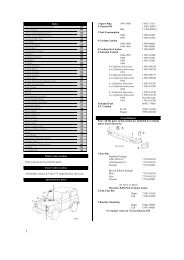
SELF-DIAGNOSTIC SYSTEM. Note location of TCM. See Fig. 1.
TCM INPUT DEVICES<br />
Brakelight Switch Signal<br />
Brakelight switch delivers input signal to TCM, indicating<br />
vehicle braking. Brakelight switch is located on brake pedal support.<br />
Cruise Control Electronic Control Unit (ECU)<br />
Cruise control unit delivers an input signal to control<br />
overdrive operation in accordance with vehicle speed when cruise<br />
control is operating. When in overdrive with cruise control on, if<br />
vehicle speed drops 2 MPH less than the set speed, overdrive is<br />
released to prevent reduction in vehicle speed. Once vehicle speed is<br />
more than the set speed, the overdrive is resumed. If coolant<br />
temperature is low, transmission will not shift into overdrive. Cruise<br />
control unit is located next to TCM. See Fig. 1.<br />
Engine Coolant Temperature (ECT) Sensor<br />
ECT sensor delivers input signal to TCM, indicating engine<br />
coolant temperature. ECT sensor is located on front of engine. See<br />
Fig. 2.<br />
Overdrive (OD) Switch<br />
The OD switch provides an input signal to TCM to indicate<br />
when overdrive is selected by operator. When OD switch is depressed to<br />
ON position, transmission will shift into 4th gear when shift lever is<br />
in "D" position, and OD OFF light on instrument panel will go off. The<br />
OD OFF light is located on instrument panel. When OD switch is<br />
released to OFF position, transmission will shift into 3rd gear, and<br />
OD OFF light on instrument panel will illuminate. The OD switch is<br />
mounted on shift lever.<br />
Park/Neutral Position (PNP) Switch Signal<br />
PNP switch delivers an input signal to TCM indicating shift<br />
lever position. Switch is located on side of transmission.<br />
Throttle Position (TP) Sensor<br />
TP sensor delivers a variable throttle position input signal<br />
to TCM. TP sensor is located on side of throttle body.<br />
Vehicle Speed Sensor (VSS)<br />
Vehicle speed signal is delivered to TCM by No. 1 and No. 2<br />
speed sensors.<br />
<strong>AUTO</strong> <strong>TRANS</strong> <strong>DIAGNOSIS</strong> - AW03-72LEArticle Text (p. 2)1995 Suzuki SidekickFor saer Nira Sakhalin Russia 69301
Fig. 1: Locating TCM Location<br />
Courtesy of Suzuki of America Corp.<br />
<strong>AUTO</strong> <strong>TRANS</strong> <strong>DIAGNOSIS</strong> - AW03-72LEArticle Text (p. 3)1995 Suzuki SidekickFor saer Nira Sakhalin Russia 69301<br />
Fig. 2: Locating ECT Sensor<br />
Courtesy of Suzuki of America Corp.
TCM OUTPUT DEVICES<br />
No. 1 & No. 2 Shift Solenoids<br />
The TCM controls transmission shifting by delivering an<br />
output signal to operate proper shift solenoid. Shift solenoids are<br />
located on transmission valve body. Shift solenoids are operated in<br />
accordance with shift lever range. If a shift solenoid malfunctions,<br />
TCM will select a gear. See FAIL SAFE GEAR POSITION table.<br />
FAIL SAFE GEAR POSITION<br />
ÄÄÄÄÄÄÄÄÄÄÄÄÄÄÄÄÄÄÄÄÄÄÄÄÄÄÄÄÄÄÄÄÄÄÄÄÄÄÄÄÄÄÄÄÄÄÄÄÄÄÄÄÄÄÄÄÄÄÄÄ<br />
Solenoid Solenoid Solenoid<br />
Application No. 1 Failure No. 2 Failure No. 1 & 2<br />
Failure<br />
"D"<br />
1st Gear ......... 3rd ......... 1st ............ OD<br />
2nd Gear ......... 3rd .......... OD ............ OD<br />
3rd Gear ......... 3rd .......... OD ............ OD<br />
OD Gear ........... OD .......... OD ........... OD<br />
"2"<br />
1st Gear ......... 3rd ......... 1st ........... 3rd<br />
2nd Gear ......... 3rd ......... 3rd ........... 3rd<br />
"L"<br />
1st Gear ......... 1st ......... 1st ........... 1st<br />
ÄÄÄÄÄÄÄÄÄÄÄÄÄÄÄÄÄÄÄÄÄÄÄÄÄÄÄÄÄÄÄÄÄÄÄÄÄÄÄÄÄÄÄÄÄÄÄÄÄÄÄÄÄÄÄÄÄÄÄÄ<br />
TCC Lock-Up Solenoid<br />
The TCM controls torque converter lock-up by delivering an<br />
output signal to TCC lock-up solenoid. Lock-up solenoid is activated<br />
when shift lever is in "D" position, and vehicle is at a predetermined<br />
specified speed.<br />
SELF-DIAGNOSTIC SYSTEM<br />
SYSTEM <strong>DIAGNOSIS</strong><br />
NOTE:<br />
Before testing transmission, ensure fluid level is correct<br />
and throttle and shift cables are properly adjusted. Ensure<br />
engine starts with shift lever in Park and Neutral to ensure<br />
proper adjustment of Park/Neutral Position (PNP) switch.<br />
Transmission must first be tested for stored trouble codes.<br />
See RETRIEVING TROUBLE CODES.<br />
The TCM monitors transmission operation and contains a selfdiagnostic<br />
system which stores a trouble code if an electronic control<br />
<strong>AUTO</strong><br />
system<br />
<strong>TRANS</strong><br />
failure<br />
<strong>DIAGNOSIS</strong><br />
or problem<br />
- AW03-72LEArticle<br />
is present.<br />
Text<br />
If<br />
(p.<br />
a problem<br />
4)1995 Suzuki is SidekickFor present saer in Nira the Sakhalin Russia 69301
No. 1 or No. 2 shift solenoids and/or vehicle speed sensor, and a<br />
trouble code is present, the TCM will deliver a signal to flash OD OFF<br />
light on instrument panel to warn the driver.<br />
RETRIEVING TROUBLE CODES<br />
NOTE:<br />
Before retrieving trouble codes, ensure battery is fully<br />
charged for proper self-diagnostic system operation. Perform<br />
diagnostic circuit check before retrieving trouble codes to<br />
ensure operation of OD OFF light. See DIAGNOSTIC CIRCUIT<br />
CHECK. Trouble codes must be cleared from TCM memory once<br />
repairs have been performed. See CLEARING TROUBLE CODES.<br />
Diagnostic Circuit Check<br />
1) Turn ignition on. Release OD switch to OFF position.<br />
Ensure OD OFF light on instrument panel illuminates. If OD OFF light<br />
does not illuminate, check OD switch and wiring circuit. See wiring<br />
diagram in WIRING DIAGRAM.<br />
2) Depress OD switch to the ON position. Ensure OD OFF light<br />
on instrument panel goes off. If OD OFF light remains on, check OD<br />
switch and wiring circuit. If OD OFF light is blinking, check for<br />
stored trouble codes. See TCM TROUBLE CODES.<br />
TCM Trouble Codes<br />
1) Turn ignition on. DO NOT start engine. Connect a jumper<br />
wire between terminals on monitor coupler. See Fig. 3. Note number of<br />
flashes from OD OFF light on instrument panel. If system operation is<br />
normal, OD OFF light will flash trouble code 12. See Fig. 4.<br />
2) If system is operating normally, and no trouble codes are<br />
present, turn ignition off and remove jumper wire. Perform manual<br />
shifting test to determine if problem is electrical or mechanical. See<br />
MANUAL SHIFTING TEST under <strong>TRANS</strong>MISSION SHIFT TESTING. Check system by<br />
symptom. See SYMPTOM TROUBLE SHOOTING.<br />
3) If a trouble code is present, OD OFF light will flash a<br />
trouble code. The number of flashes will equal first digit of trouble<br />
code. After a one second pause, second digit will be displayed. See<br />
Fig. 4.<br />
4) If more than one trouble code is present, next trouble<br />
code will be displayed after a 3 second pause. Smallest number trouble<br />
code will be displayed first. Trouble codes will be repeated. Once<br />
trouble code is obtained, determine probable cause. See<br />
TROUBLE CODE IDENTIFICATION table.<br />
NOTE:<br />
Manufacturer does not provide diagnostic trouble code<br />
testing information. Only symptom trouble shooting and<br />
component testing procedures are given. For additional<br />
component information, see appropriate ENGINE PERFORMANCE<br />
article.<br />
<strong>AUTO</strong> <strong>TRANS</strong> DIA
TROUBLE CODE IDENTIFICATION<br />
ÄÄÄÄÄÄÄÄÄÄÄÄÄÄÄÄÄÄÄÄÄÄÄÄÄÄÄÄÄÄÄÄÄÄÄÄÄÄÄÄÄÄÄÄÄÄÄÄÄÄÄÄÄÄÄÄÄÄÄÄ<br />
Trouble Code<br />
(1) Probable Cause<br />
12 ............................... System Operation Normal<br />
21 ..................... No. 1 Shift Solenoid Open Circuit<br />
22 .................... No. 1 Shift Solenoid Short Circuit<br />
23 ..................... No. 2 Shift Solenoid Open Circuit<br />
24 .................... No. 2 Shift Solenoid Short Circuit<br />
25 ............................. TCC Solenoid Open Circuit<br />
26 ............................ TCC Solenoid Short Circuit<br />
31 ............ Vehicle Speed Sensor Open Or Short Circuit<br />
32 ................ Throttle Position Sensor Short Circuit<br />
33 ................. Throttle Position Sensor Open Circuit<br />
34 ................ Defective Park/Neutral Position Switch<br />
36 .............. (2) No Signal-Both Vehicle Speed Sensors<br />
(1) - Check listed component for probable cause. Also check<br />
wiring and connections of specified component.<br />
(2) - No signal from both transmission and speedometer mounted<br />
vehicle speed sensors.<br />
ÄÄÄÄÄÄÄÄÄÄÄÄÄÄÄÄÄÄÄÄÄÄÄÄÄÄÄÄÄÄÄÄÄÄÄÄÄÄÄÄÄÄÄÄÄÄÄÄÄÄÄÄÄÄÄÄÄÄÄÄ<br />
Fig. 3: Identifying Monitor Coupler Terminals<br />
Courtesy of Toyota Motor Sales, U.S.A., Inc.<br />
<strong>AUTO</strong> <strong>TRANS</strong> <strong>DIAGNOSIS</strong> - AW03-72LEArticle Text (p. 6)1995 Suzuki SidekickFor saer N
Fig. 4: Identifying Trouble Code Displays<br />
Courtesy of Toyota Motor Sales, U.S.A., Inc.<br />
CLEARING TROUBLE CODES<br />
Once repairs have been performed, trouble codes must be<br />
cleared from TCM memory. To clear, disconnect negative battery cable<br />
for at least 10 seconds.<br />
<strong>TRANS</strong>MISSION SHIFT TESTING<br />
MANUAL SHIFTING TEST<br />
NOTE:<br />
Perform manual shifting test if no trouble codes are<br />
present. Manual shifting test determines if problem is an<br />
electrical or mechanical related problem.<br />
1) Start and operate vehicle until normal operating<br />
temperature is achieved. Disconnect TCM harness connector. See Fig. 1.<br />
Road test vehicle and ensure transmission gear changes correspond with<br />
shift lever position. See GEAR APPLICATION table.<br />
2) If an abnormality is present, problem is mechanically<br />
related. If all gears are correct, perform trouble shooting in<br />
accordance with symptom. See SYMPTOM TROUBLE SHOOTING. Turn ignition<br />
off.<br />
3) Reconnect TCM harness connector. Clear trouble codes from<br />
TCM memory, as disconnecting electrical connector may set a trouble<br />
code. See CLEARING TROUBLE CODES.<br />
<strong>AUTO</strong> GEAR APPLICATION<br />
<strong>TRANS</strong> <strong>DIAGNOSIS</strong> - AW03-72LEArticle Text (p. 7)1995 Suzuki SidekickFor saer Nira Sakhalin Russia 69301<br />
ÄÄÄÄÄÄÄÄÄÄÄÄÄÄÄÄÄÄÄÄÄÄÄÄÄÄÄÄÄÄÄÄÄÄÄÄÄÄÄÄÄÄÄÄÄÄÄÄÄÄÄÄÄÄÄÄÄÄÄÄ<br />
Shift Lever Position<br />
Gear<br />
"D" ............................................ Overdrive
"2" ............................................. 3rd Gear<br />
"L" ............................................. 1st Gear<br />
"R" .............................................. Reverse<br />
"P" ................................................. Park<br />
ÄÄÄÄÄÄÄÄÄÄÄÄÄÄÄÄÄÄÄÄÄÄÄÄÄÄÄÄÄÄÄÄÄÄÄÄÄÄÄÄÄÄÄÄÄÄÄÄÄÄÄÄÄÄÄÄÄÄÄÄ<br />
SYMPTOM TROUBLE SHOOTING<br />
DOES NOT SHIFT<br />
1) Ensure engine and transmission are at normal operating<br />
temperature. Retrieve trouble codes. See RETRIEVING TROUBLE CODES. If<br />
a trouble code is present, repair as needed. Clear trouble codes. See<br />
CLEARING TROUBLE CODES. If no trouble codes are present, go to next<br />
step.<br />
2) Perform manual shifting test. See MANUAL SHIFTING TEST<br />
under <strong>TRANS</strong>MISSION SHIFT TESTING. Raise and support vehicle. Access<br />
TCM harness connector (leave connected). See Fig. 1. Go to next step.<br />
3) Using a DVOM, measure voltage (backprobe) between chassis<br />
ground and TCM harness connector terminal S1, then terminal S2 while<br />
operating vehicle through all gears with shift selector in "D"<br />
position. See Fig. 5. Record readings and compare with table. See<br />
SHIFT SOLENOID VOLTAGE table. Go to next step.<br />
SHIFT SOLENOID VOLTAGE<br />
ÄÄÄÄÄÄÄÄÄÄÄÄÄÄÄÄÄÄÄÄÄÄÄÄÄÄÄÄÄÄÄÄÄÄÄÄÄÄÄÄÄÄÄÄÄÄÄÄÄÄÄÄÄÄÄÄÄÄÄÄÄÄÄÄÄÄÄÄÄÄ<br />
Application<br />
1st Gear 2nd Gear 3rd Gear OD Gear<br />
No. 1 Shift Solenoid<br />
10-14 Volts ....... 10-14 Volts .... 0 Volt ........... 0 Volt<br />
No. 2 Shift Solenoid<br />
0 Volt ............ 10-14 Volts .. 10-14 Volts ........ 0 Volt<br />
ÄÄÄÄÄÄÄÄÄÄÄÄÄÄÄÄÄÄÄÄÄÄÄÄÄÄÄÄÄÄÄÄÄÄÄÄÄÄÄÄÄÄÄÄÄÄÄÄÄÄÄÄÄÄÄÄÄÄÄÄÄÄÄÄÄÄÄÄÄÄ<br />
4) If any reading is not as specified, go to next step. If<br />
all readings are as specified, inspect shift solenoids. See SHIFT<br />
SOLENOIDS under COMPONENT TESTING. If shift solenoids are okay,<br />
inspect and repair circuits between TCM and shift solenoids as needed.<br />
If circuits are okay, replace TCM and retest.<br />
5) Repeat vehicle operation through all gears while<br />
monitoring voltage between chassis ground and TCM harness connector<br />
terminal "L", then terminal "2". Reading should be zero volts at each<br />
terminal. If readings are not as specified, replace Park/Neutral<br />
Position (PNP) switch and retest. If both readings are zero volts,<br />
replace TCM and retest.<br />
<strong>AUTO</strong> <strong>TRANS</strong> <strong>DIAGNOSIS</strong> -
Fig. 5: Identifying TCM Harness Connector Terminals<br />
Courtesy of Suzuki of America Corp.<br />
INCORRECT SHIFT SPEEDS<br />
1) Ensure engine and transmission are at normal operating<br />
temperature. Retrieve trouble codes. See RETRIEVING TROUBLE CODES. If<br />
a trouble code is present, repair as needed. Clear trouble codes. See<br />
CLEARING TROUBLE CODES. If no trouble codes are present, go to next<br />
step.<br />
2) Access TCM harness connector (leave connected). See<br />
Fig. 1. Using a DVOM, measure voltage (backprobe) between chassis<br />
ground and TCM harness connector terminal TH. See Fig. 5. Go to next<br />
step.<br />
3) Slowly depress accelerator pedal to Wide Open Throttle<br />
(WOT). Monitor voltage while depressing throttle pedal. Voltage should<br />
decrease as throttle is depressed. Voltage should be within the<br />
following range: battery voltage multiplied by .95 (idle position) to<br />
battery voltage multiplied by .39 (WOT). Go to next step.<br />
4) If voltage is not within range in step 3), or changes<br />
erratically, inspect Throttle Position (TP) sensor. See appropriate<br />
ENGINE PERFORMANCE article. If voltage is within range, turn ignition<br />
off and go to next step.<br />
5) Disconnect TCM harness connector. Disconnect speedometer<br />
cable from transmission. Using a DVOM, measure resistance between<br />
chassis ground and TCM harness connector terminal SPM. See Fig. 5.<br />
Monitor DVOM while turning speedometer cable. Go to next step.<br />
6) If reading pulses between zero ohms and infinity 4 times<br />
per revolution, go to next step. If reading is not as specified,<br />
inspect for a broken speedometer cable, faulty sensor in speedometer<br />
or faulty circuit between speedometer and TCM.<br />
7) Ensure ignition is off. Reconnect TCM harness connector.<br />
Turn ignition on. Using a DVOM, measure voltage (backprobe) between<br />
chassis ground and TCM harness connector terminal PWR. See Fig. 5. If<br />
reading is 5 volts with shift selector in "N" position, and zero volts<br />
in "P" position, replace TCM and retest. If readings<br />
<strong>AUTO</strong> <strong>TRANS</strong> <strong>DIAGNOSIS</strong> - AW03-72LEArticle Text (p. 9)1995 Suzuki SidekickFor<br />
are not<br />
saer<br />
as<br />
Nira Sakhalin Russia 69301<br />
specified, replace PNP switch and retest. If problem is still present,
inspect and repair circuits between PNP switch and TCM.<br />
NO UPSHIFT TO OVERDRIVE<br />
1) Ensure engine and transmission are at normal operating<br />
temperature. Retrieve trouble codes. See RETRIEVING TROUBLE CODES. If<br />
a trouble code is present, repair as needed. Clear trouble codes. See<br />
CLEARING TROUBLE CODES. If no trouble codes are present, go to next<br />
step.<br />
2) Perform manual shifting test. See MANUAL SHIFTING TEST<br />
under <strong>TRANS</strong>MISSION SHIFT TESTING. Reconnect TCM harness connector.<br />
Raise and support vehicle. Using a DVOM, measure voltage (backprobe)<br />
between chassis ground and TCM harness connector terminal S1, then<br />
terminal S2 while operating vehicle through all gears with shift<br />
selector in "D" position. See Fig. 5. Record readings and compare with<br />
table. See SHIFT SOLENOID VOLTAGE table. Go to next step.<br />
SHIFT SOLENOID VOLTAGE<br />
ÄÄÄÄÄÄÄÄÄÄÄÄÄÄÄÄÄÄÄÄÄÄÄÄÄÄÄÄÄÄÄÄÄÄÄÄÄÄÄÄÄÄÄÄÄÄÄÄÄÄÄÄÄÄÄÄÄÄÄÄÄÄÄÄÄÄÄÄÄÄ<br />
Application<br />
1st Gear 2nd Gear 3rd Gear OD Gear<br />
No. 1 Shift Solenoid<br />
10-14 Volts ....... 10-14 Volts ... 0 Volt ............ 0 Volt<br />
No. 2 Shift Solenoid<br />
0 Volt ............ 10-14 Volts ... 10-14 Volts ........ 0 Volt<br />
ÄÄÄÄÄÄÄÄÄÄÄÄÄÄÄÄÄÄÄÄÄÄÄÄÄÄÄÄÄÄÄÄÄÄÄÄÄÄÄÄÄÄÄÄÄÄÄÄÄÄÄÄÄÄÄÄÄÄÄÄÄÄÄÄÄÄÄÄÄÄ<br />
3) If any reading is not within specification, go to next<br />
step. If all readings are within specification, inspect shift<br />
solenoids. See SHIFT SOLENOIDS under COMPONENT TESTING. If shift<br />
solenoids are okay, inspect and repair circuits between TCM and shift<br />
solenoids as needed. If circuits are okay, replace TCM and retest.<br />
4) Repeat vehicle operation through all gears while<br />
monitoring voltage between chassis ground and TCM harness connector<br />
terminal "L", then terminal "2". If reading is zero volts for both<br />
circuits, go to next step. If reading is not as specified, replace<br />
Park/Neutral Position (PNP) switch and retest.<br />
5) Measure voltage (backprobe) between chassis ground and TCM<br />
harness connector terminal OD. See Fig. 5. If reading is 5 volts with<br />
OD switch in OFF position, and zero volts in ON position, go to next<br />
step. If reading is not as specified, inspect OD switch and applicable<br />
circuits. See wiring diagram in WIRING DIAGRAM. Repair as needed.<br />
6) Measure voltage (backprobe) between chassis ground and TCM<br />
harness connector terminal WT. See Fig. 5. If reading is zero volts<br />
with engine coolant temperature below 77øF (25øC), and battery voltage<br />
with engine coolant temperature above 86øF (30øC), go to step 8). If<br />
reading is not as specified, go to next step.<br />
<strong>AUTO</strong> <strong>TRANS</strong>
7) Inspect ECT sensor. See ENGINE COOLANT TEMPERATURE sensor<br />
under COMPONENT TESTING. If ECT tests okay, see appropriate ENGINE<br />
PERFORMANCE article for further diagnostic information.<br />
8) Measure voltage (backprobe) between chassis ground and TCM<br />
harness connector terminal L4. If reading is zero volts with transfer<br />
case in 4WD position, and battery voltage in 2WD position, replace TCM<br />
and retest. If reading is not as specified, replace 4WD switch<br />
(located on side of transfer case).<br />
NO TCC LOCK-UP<br />
1) Ensure engine and transmission are at normal operating<br />
temperature. Retrieve trouble codes. See RETRIEVING TROUBLE CODES. If<br />
a trouble code is present, repair as needed. Clear trouble codes. See<br />
CLEARING TROUBLE CODES. If no trouble codes are present, go to next<br />
step.<br />
2) Raise and support vehicle. Using a DVOM, measure voltage<br />
(backprobe) between chassis ground and TCM harness connector terminal<br />
S3 while operating vehicle through all forward gears with shift<br />
selector in "D" position. See Fig. 5. Go to next step.<br />
3) Ensure mode switch is in "N" (normal) position. Accelerate<br />
to 35 MPH. If battery voltage is present, inspect TCC solenoid. See<br />
SHIFT SOLENOIDS under COMPONENT TESTING. Replace as needed and retest.<br />
If battery voltage is not present, measure voltage (backprobe) between<br />
chassis ground and TCM harness connector terminal BK. See Fig. 5. Go<br />
to next step.<br />
4) Depress and release brake pedal while monitoring voltage.<br />
If reading is zero volts with pedal released, and battery voltage with<br />
pedal depressed, go to next step. If reading is not as specified,<br />
inspect brake switch and circuit. Repair as needed.<br />
5) Measure voltage (backprobe) between chassis ground and TCM<br />
harness connector terminal WT. See Fig. 5. If reading is zero volts<br />
with engine coolant temperature below 77øF (25øC), and battery voltage<br />
with engine coolant temperature above 86øF (30øC), go to step 7). If<br />
reading is not as specified, go to next step.<br />
6) Inspect ECT sensor. See<br />
ENGINE COOLANT TEMPERATURE (ECT) SENSOR under COMPONENT TESTING. If<br />
ECT is okay, see appropriate ENGINE PERFORMANCE article for further<br />
diagnostic information.<br />
7) Measure voltage (backprobe) between chassis ground and TCM<br />
harness connector terminal L4. If reading is zero volts with transfer<br />
case in 4WD position, and battery voltage in 2WD position, replace TCM<br />
and retest. If reading is not as specified, replace 4WD switch<br />
(located on side of transfer case).<br />
COMPONENT TESTING<br />
<strong>AUTO</strong> <strong>TRANS</strong> <strong>DIAGNOSIS</strong> - AW03-72LEArticle
ENGINE COOLANT TEMPERATURE (ECT) SENSOR<br />
Remove sensor from intake manifold and place in water with a<br />
thermometer. Heat water to specified temperature and check resistance.<br />
See ENGINE COOLANT TEMPERATURE (ECT) SENSOR RESISTANCE table. Replace<br />
sensor if resistance is not within specification.<br />
ENGINE COOLANT TEMPERATURE (ECT) SENSOR RESISTANCE TABLE<br />
ÄÄÄÄÄÄÄÄÄÄÄÄÄÄÄÄÄÄÄÄÄÄÄÄÄÄÄÄÄÄÄÄÄÄÄÄÄÄÄÄÄÄÄÄÄÄÄÄÄÄÄÄÄÄÄÄÄÄÄÄ<br />
Temp.<br />
Ohms<br />
øF (øC)<br />
32 (0) .............................................. 5880<br />
68 (20) ........................................ 2210-2690<br />
104 (40) ............................................ 1140<br />
140 (60) ............................................. 580<br />
176 (80) ......................................... 290-350<br />
ÄÄÄÄÄÄÄÄÄÄÄÄÄÄÄÄÄÄÄÄÄÄÄÄÄÄÄÄÄÄÄÄÄÄÄÄÄÄÄÄÄÄÄÄÄÄÄÄÄÄÄÄÄÄÄÄÄÄÄÄ<br />
SOLENOIDS<br />
1) Obtain access to TCM. See Fig. 1. Ensure ignition is off.<br />
Disconnect TCM harness connector. Turn ignition on. Using a fused<br />
jumper wire, connect one end to TCM harness connector terminal +B.<br />
With other end, probe terminals S1, S2 and S3, one at a time. See<br />
Fig. 5. Ensure a "clicking" sound can be heard when battery voltage is<br />
applied. Replace solenoid if no sound is heard.<br />
2) To check solenoid seals, apply battery voltage to<br />
solenoid. Apply ATF to solenoid with battery voltage connected. See<br />
Fig. 6. ATF should pass through solenoid. Remove battery voltage.<br />
Ensure ATF does not pass through solenoid. Replace solenoid if<br />
defective.<br />
<strong>AUTO</strong> <strong>TRANS</strong> <strong>DIAGNOSIS</strong> - AW03-72LEArticle Text (p. 12)1995 Suzuki SidekickFor saer Nira Sakhalin Russia 6930
Fig. 6: Checking Solenoids<br />
Courtesy of Toyota Motor Sales, U.S.A., Inc.<br />
PARK/NEUTRAL POSITION (PNP) SWITCH<br />
<strong>AUTO</strong> <strong>TRANS</strong> <strong>DIAGNOSIS</strong> - AW03-72LEArticle Text (p. 13)1995 Suzuki SidekickFor saer Nira Sakhalin Russia 6930<br />
Disconnect PNP switch harness connector. Switch is located on<br />
side of transmission. Using a DVOM, check for continuity between<br />
specified terminals in accordance with shift lever position. See<br />
Fig. 7. Replace switch if defective.<br />
PARK/NEUTRAL POSITION SWITCH CONTINUITY<br />
ÄÄÄÄÄÄÄÄÄÄÄÄÄÄÄÄÄÄÄÄÄÄÄÄÄÄÄÄÄÄÄÄÄÄÄÄÄÄÄÄÄÄÄÄÄÄÄÄÄÄÄÄÄÄÄÄÄÄÄÄ<br />
Shift Lever Position Continuity Between Terminals<br />
"P" ......................................... 5 & 6, 8 & 9<br />
"R" ................................................ 4 & 9<br />
"N" ......................................... 5 & 6, 7 & 9<br />
"D" ................................................ 3 & 9<br />
"2" ................................................ 2 & 9<br />
"L" ................................................ 1 & 9
ÄÄÄÄÄÄÄÄÄÄÄÄÄÄÄÄÄÄÄÄÄÄÄÄÄÄÄÄÄÄÄÄÄÄÄÄÄÄÄÄÄÄÄÄÄÄÄÄÄÄÄÄÄÄÄÄÄÄÄÄ<br />
Fig. 7: Identifying Park/Neutral Position (PNP) Switch Terminals<br />
Courtesy of Toyota Motor Sales, U.S.A., Inc.<br />
VEHICLE SPEED SENSOR<br />
Ensure ignition is off. Disconnect TCM harness connector. See<br />
Fig. 1. Using a DVOM, measure resistance between TCM harness connector<br />
terminals SP and SPG. See Fig. 5. Resistance should be 387-473 ohms.<br />
Replace as needed.<br />
WIRING DIAGRAM<br />
<strong>AUTO</strong> <strong>TRANS</strong> <strong>DIAGNOSIS</strong> -
<strong>AUTO</strong> <strong>TRANS</strong> <strong>DIAGNOSIS</strong> - AW03-72LEArticle Text (p. 15)1995 Suzuki SidekickFor saer Nira Sakhalin Russia 6930<br />
Fig. 8: Transmission Wiring Diagram (1995 Suzuki Sidekick)<br />
END OF ARTICLE


