Expression - ETC
Expression - ETC
Expression - ETC

You also want an ePaper? Increase the reach of your titles
YUMPU automatically turns print PDFs into web optimized ePapers that Google loves.
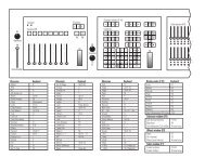
<strong>Expression</strong><br />
The Moving Lights (ML) Module - Installation instructions<br />
The ML Module provides the encoder and pagebutton controls that are standard features on the <strong>Expression</strong><br />
3 and Insight 3 consoles. This hardware option is available for <strong>Expression</strong> 2 family consoles (<strong>Expression</strong><br />
2x, Concept 2x, Insight 2x, Insight 2 and Impression 2). A mouse or other pointing device may be<br />
attached to the ML Module for added convenience.<br />
Optional bracket mounting<br />
The ML Module can be used freestanding on any flat surface adjacent to the console or it can be firmly<br />
attached to the console. If you choose to attach the ML Module to the console, follow the procedure<br />
below before connecting any cables to it. The bracket and all fasteners you need are included in the ML<br />
Module kit. If not mounting the ML Module to the console, skip to Electrical connections below.<br />
CAUTION: The mounting hardware is not designed to fully support the ML Module. Never allow it to<br />
protrude unsupported beyond the edge of the surface on which the console rests.<br />
Mount the module to the console with reference to the instructions and illustration below:<br />
1. Secure the mounting bracket to the base of the ML Module using the three flat-head screws.<br />
2. Loosen the two rollers knobs at the bottom corners of the facepanel.<br />
3. Lift the lower edge of the facepanel to rotate it upward, exposing the inside of the chassis.<br />
4. With the module resting on the table, line up the right edge of the ML Module with the right edge of<br />
the facepanel (not the chassis).<br />
5. Fasten the mounting bracket to<br />
the console using four<br />
thumbscrews inserted<br />
through two chassis<br />
vent slots from the<br />
inside and connecting<br />
to PEM nuts on the<br />
mounting bracket. For<br />
earlier model <strong>Expression</strong><br />
family consoles,<br />
use the bracket PEM nuts<br />
at X. For later model<br />
<strong>Expression</strong> family consoles,<br />
use the bracket PEM nuts at Y.<br />
6. Tighten the thumbscrews<br />
securely, making sure the ML<br />
Module rests on the same surface<br />
Z<br />
as the console.<br />
X<br />
7. Lower the facepanel carefully and<br />
secure it to the chassis with the bottom<br />
roller knobs.<br />
4131L1001 Revised 4/98<br />
DC Input<br />
9V<br />
300 mA<br />
Y<br />
Mouse<br />
RS232
Electrical connections<br />
Never make or break electrical connections with the console power on. With console power off, connect<br />
the ML Module cable to the console port labeled Digitizer/Serial. Since they share the same port, you<br />
cannot use the ML Module and a digitizer at the same time.<br />
Plug one end of the ML Module’s power cord into the labeled receptacle Z at one end of the Module.<br />
Plug the power supply on the cord into a wall outlet or power strip. A power strip is especially convenient<br />
if it has its own on/off switch because both the console and ML Module power supply can be plugged<br />
into it and powered on or off together.<br />
Software enabling<br />
Enable the ML Module (and simultaneously disable the Designer's Worksheet function) with the following<br />
procedure:<br />
1. Switch on the console power.<br />
2. Press [Setup] [6], Option Settings, [Enter] to go to the Options Settings menu.<br />
3. Press [1][2], External Port, [Enter].<br />
4. Press [2] [Enter] to enable the ML Module.<br />
NOTE: If you later decide you want to use the Designer's Worksheet function rather than the ML<br />
Module, you must a) connect a digitizer in place of the ML Module to the Digitizer/Serial port, and b)<br />
enable the digitizer by pressing [1] in step 4 of the procedure above.<br />
Pointing device installation<br />
You may attach any Microsoft-compatible type of pointing device to the ML Module, including a mouse,<br />
trackball or trackpad.<br />
Switch off the console and the ML Module. Cable the pointing device to the RS232 port located on an<br />
end panel of the ML Module (see the illustration on the other side).<br />
Device check<br />
Operation<br />
The pointing device should be ready for use when the console and module are switched on. Verify normal<br />
operation by patching fixtures as explained under Working with Moving Lights in the <strong>Expression</strong> User<br />
Manual Supplement, page 16. Movement of the pointing device should control pan and tilt levels; its<br />
buttons should step through fixture selections in the Fixture Box window. If the device doesn’t function<br />
normally, proceed as follows:<br />
1. Verify that the pointing device is Microsoft compatible.<br />
2. Verify that the pointing device works normally in another system, such as in a computer.<br />
3. If steps 1 and 2 don’t correct the problem, call <strong>ETC</strong> Technical Services at 800-775-4382.<br />
Power supply<br />
See the <strong>Expression</strong> User Manual Supplement for information about how to use the ML Module and<br />
associated pointing device with the console.<br />
The ML Module is powered by a plug-in external supply rated at 9 volts DC (unregulated) and 300 mA. If<br />
replacing the power supply, make sure the connector is polarized negative on the inside and positive on<br />
the outside. Also, the connector must have a 2.1 mm inside diameter and a 5.5 mm outside diameter.<br />
4131L1001 Revised 4/98