MUNICIPAL CORPORATION JALANDHAR
MUNICIPAL CORPORATION JALANDHAR
MUNICIPAL CORPORATION JALANDHAR

Create successful ePaper yourself
Turn your PDF publications into a flip-book with our unique Google optimized e-Paper software.
The exhauster / compressor will be provided with:<br />
11<br />
a. Convection air-cooling system<br />
b. Forced Oil Lubrication system<br />
c. Incorporated Check valve<br />
d. Incorporated 4 – way valve<br />
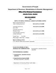
TECHNICAL DATA<br />
Delivery : Min. 13850 LPM free air flow<br />
Max Rated Vacuum : 90%<br />
Operating Vacuum : 200 bar (80% Vacuum)<br />
Operating Pressure : 1.0 bar gauge (absolute)<br />
The 4 – way change – over valve shall enable the unit to change quickly from the pressure to the suction<br />
mode and vice – versa.<br />
A pump inlet Filter of adequate capacity shall be incorporated in the system for the protection of the pump<br />
against any ingress of foreign particles, in both the suction and the overpressure modes of operation.<br />
Pressure relief and vacuum relief valves shall be line mounted to protect the equipment and system from<br />
over pressure and excessive vacuum respectively. The valves shall be factory set to control the operating<br />
pressure and vacuum parameters of the system.<br />
1.6 SUCTION HOSE<br />
5 sections of 100 mm dia. and 3 Mtrs. Long, heavy duty, lightweight, PVC hose along with quick connect<br />
hose-end fittings, shall be provided for the suction application.<br />
One, light weight hose-end suction nozzle with a suitable quick connect coupling shall be supplied with<br />
the equipment as a standard accessory.<br />
Two lockable hose racks for the stowage of hoses shall be provided on either side of the equipment.<br />
1.7 PIPING<br />
System piping subject to high pressure should be of steel and forged steel fittings. These rubber<br />
connection hoses should not deform or get damaged due to compressed air heat generated when the<br />
equipment is used in the pressure mode.<br />
The pipes should be clamped sufficiently to absorb vibrations and should be easily accessible for<br />
maintenance.<br />
1.8 CONTROLS<br />
All indicators and control elements required for control and monitoring will be located at a convenient<br />
operating position on the equipment and on the left-hand side of the vehicle.