PROFESSIONAL DEVELOPMENT SERIES Design of Reinforced ...
PROFESSIONAL DEVELOPMENT SERIES Design of Reinforced ...
PROFESSIONAL DEVELOPMENT SERIES Design of Reinforced ...

Create successful ePaper yourself
Turn your PDF publications into a flip-book with our unique Google optimized e-Paper software.
<strong>Design</strong> <strong>of</strong> <strong>Reinforced</strong><br />
Concrete Floor Systems<br />
By David A. Fanella, Ph.D., S.E., P.E., and Iyad M. Alsamsam, Ph.D., S.E., P.E.<br />
<strong>PROFESSIONAL</strong><br />
<strong>DEVELOPMENT</strong><br />
<strong>SERIES</strong>
Pr<strong>of</strong>essional Development Series<br />
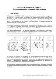
<strong>Reinforced</strong> concrete floor<br />
systems can provide an<br />
economical solution to a<br />
wide variety <strong>of</strong> situations. Numerous types <strong>of</strong><br />
nonprestressed and prestressed floor systems<br />
are available to satisfy virtually any span and<br />
loading condition, see Figure 1. Selecting the<br />
most effective system for a given set <strong>of</strong><br />
constraints can be vital to achieving overall<br />
economy, especially for low- and mid-rise<br />
buildings and for buildings subjected to relatively<br />
low lateral forces where the cost <strong>of</strong> the<br />
lateral-force-resisting system is minimal.<br />
General considerations<br />
Concrete, reinforcement, and formwork are the three<br />
primary expenses in cast-in-place concrete floor construction<br />
to consider throughout the design process, but especially<br />
during the initial planning stages. Of these three,<br />
formwork comprises about 50 to 60 percent <strong>of</strong> the total cost<br />
Continuing Education<br />
The Pr<strong>of</strong>essional Development Series is a unique opportunity<br />
to earn continuing education credit by reading specially<br />
focused, sponsored articles in Structural Engineer. If you read<br />
the following article, display your understanding <strong>of</strong> the stated<br />
learning objectives, and follow the simple instructions, you can<br />
fulfill a portion <strong>of</strong> your continuing education requirements at<br />
no cost to you.<br />
Instructions<br />
First, review the learning objectives below, then read the<br />
Pr<strong>of</strong>essional Development Series article. Next complete the<br />
quiz and submit your answers to the Pr<strong>of</strong>essional<br />
Development Series sponsor. Submittal instructions are<br />
provided on the Reporting Form, which follows the quiz and is<br />
also available for download at www.gostructural.com/se-pdh.<br />
Your quiz answers will be graded by the Pr<strong>of</strong>essional<br />
Development Series sponsor. If you answer at least 80 percent<br />
<strong>of</strong> the questions correctly, you will receive a certificate <strong>of</strong><br />
completion from the Pr<strong>of</strong>essional Development Series sponsor<br />
within 90 days and will be awarded 2.0 pr<strong>of</strong>essional development<br />
hour (equivalent to 0.2 continuing education unit in<br />
most states).<br />
Note: It is the responsibility <strong>of</strong> the licensee to determine if this<br />
method <strong>of</strong> continuing education meets his or her governing<br />
board(s) <strong>of</strong> registration’s requirements.<br />
Learning Objectives<br />
This tutorial focuses on cast-in-place concrete floor systems<br />
with nonprestressed reinforcement. The reader will learn<br />
methods <strong>of</strong> analysis and design for these types <strong>of</strong> floor systems<br />
that satisfy The American Concrete Institute’s Building Code<br />
Requirements for Structural Concrete (ACI 318-05). All referenced<br />
items are from ACI 318-05, unless noted otherwise.<br />
Pr<strong>of</strong>essional Development Series Sponsor<br />
Portland Cement Association<br />
a<br />
c<br />
e<br />
b<br />
d<br />
Figure 1: Cast-in-place reinforced<br />
concrete floor systems (a)<br />
flat plate, (b) flat slab, (c) oneway<br />
joist, (d) wide-module joist,<br />
and (e) two-way joist<br />
and has the greatest influence on the overall cost <strong>of</strong> the floor<br />
system. The cost <strong>of</strong> the concrete, including placing and<br />
finishing, typically accounts for about 25 to 30 percent <strong>of</strong><br />
the overall cost. The reinforcing steel has the lowest influence<br />
on overall cost.<br />
To achieve overall economy, designers should satisfy the<br />
following three basic principles <strong>of</strong> formwork economy:<br />
Specify readily available standard form sizes. Rarely will<br />
custom forms be economical, unless they are required in a<br />
quantity that allows for mass production.<br />
Repeat sizes and shapes <strong>of</strong> the concrete members<br />
wherever possible. Repetition allows reuse <strong>of</strong> forms from<br />
bay to bay and from floor to floor.<br />
Strive for simple formwork. In cast-in-place concrete<br />
construction, economy is rarely achieved by reducing quantities<br />
<strong>of</strong> materials. For example, varying the depth <strong>of</strong> a beam<br />
2 PDH Special Advertizing Section — Portland Cement Association
<strong>Design</strong> <strong>of</strong> <strong>Reinforced</strong> Concrete Floor Systems<br />
with the loading and span variations would give a moderate<br />
savings in materials, but would create substantial additional<br />
costs in formwork, resulting in a more expensive structure.<br />
The simplest and most cost-effective solution would be<br />
providing a constant beam depth and varying the reinforcement<br />
along the span. Simple formwork can make construction<br />
time shorter, resulting in a building that can be<br />
occupied sooner.<br />
Additional parameters must be considered when selecting<br />
an economical floor system. In general, span lengths, floor<br />
loads, and geometry <strong>of</strong> a floor panel all play a key role in the<br />
selection process. Detailed information on how to select<br />
economical concrete floor systems for a wide variety <strong>of</strong> situations<br />
can be found in the following Portland Cement<br />
Association (PCA) publications: Concrete Floor Systems —<br />
Guide to Estimating and Economizing (SP041), and Long-<br />
Span Concrete Floor Systems (SP339).<br />
Preliminary sizing<br />
Before analyzing the floor system, designers must assume<br />
preliminary member sizes. Typically, the slab and/or beam<br />
thickness is determined first to ensure that the deflection<br />
requirements <strong>of</strong> Section 9.5 are satisfied.<br />
For solid, one-way slabs and beams that are not supporting<br />
or attached to partitions or other construction likely to be<br />
damaged by large deflections, Table 9.5(a) may be used to<br />
determine minimum thickness, h. For continuous one-way<br />
slabs and beams, determine h based on one end continuous,<br />
since this thickness will satisfy deflection criteria for all spans.<br />
The preliminary thickness <strong>of</strong> a solid one-way slab with normal<br />
weight concrete and Grade 60 reinforcement is l/24, where<br />
l is the span length in inches. Similarly, for beams, minimum<br />
h is l/18.5. Deflections need not be computed when a thickness<br />
at least equal to the minimum is provided.<br />
For nonprestressed, two-way slabs, minimum thickness<br />
requirements are given in Section 9.5.3. By satisfying these<br />
minimum requirements, which are illustrated in Figure 2 for<br />
Grade 60 reinforcement, deflections need not be computed.<br />
Deflection calculations for two-way slabs are complex, even<br />
when linear elastic behavior is assumed. In Figure 2, α f is the<br />
ratio <strong>of</strong> the flexural stiffness <strong>of</strong> a beam section to the flexural<br />
stiffness <strong>of</strong> a width <strong>of</strong> slab bounded laterally by centerlines <strong>of</strong><br />
adjacent panels (see Section 13.6.1.6), and α fm is the average<br />
value <strong>of</strong> α f for all beams on the edges <strong>of</strong> a panel. For two-way<br />
construction, l n is the clear span length in the long direction<br />
measured face-to-face <strong>of</strong> supports.<br />
When two-way slab systems are supported directly on<br />
columns, shear around the columns is critically important,<br />
especially at exterior slab-column connections where the<br />
total exterior slab moment must be transferred directly to the<br />
column. Minimum slab thickness for flat plates <strong>of</strong>ten is<br />
governed by this condition.<br />
Once the depth <strong>of</strong> a beam has been computed, the width<br />
b w can be determined based on moment strength. The<br />
following equation, which is derived in the PCA’s Simplified<br />
<strong>Design</strong> (EB104) Handbook, can be used to<br />
determine b w for the typical case when<br />
f ’ c = 4,000 pounds per square inch (psi) and<br />
f y = 60 kips per square inch (ksi):<br />
In this equation, M u is the largest factored moment along<br />
the span (foot-kips) and d is the required effective depth <strong>of</strong><br />
the beam (inches), based on deflection criteria. For beams<br />
with one layer <strong>of</strong> reinforcement, d can be taken equal to<br />
h – 2.5 inches, while for joists and slabs, d can be taken as<br />
h – 1.25 inches. Similar sizing equations can be derived for<br />
other concrete strengths and grades <strong>of</strong> reinforcement.<br />
In the preliminary design stage, it is important for the<br />
engineer to consider fire resistance. Building codes regulate<br />
the fire resistance <strong>of</strong> the various elements and assemblies <strong>of</strong><br />
a building structure. Fire resistance must be considered<br />
when choosing a slab thickness. Table 721.2.2.1 in the<br />
International Code Council’s 2003 International Building<br />
Code (IBC) contains minimum reinforced concrete slab<br />
thickness for fire-resistance ratings <strong>of</strong> one to four hours,<br />
based on the type <strong>of</strong> aggregate used in the concrete mix. In<br />
general, concrete member thickness required for structural<br />
purposes is usually adequate to provide at least a two-hour<br />
fire-resistance rating. Adequate cover to the reinforcing steel<br />
is required to protect it from the effects <strong>of</strong> fire. Cover thicknesses<br />
for reinforced concrete floor slabs and beams are<br />
given in IBC Tables 721.2.3(1) and 721.2.3(3), respectively.<br />
The minimum cover requirements in Section 7.7.1 <strong>of</strong> ACI<br />
14<br />
13<br />
12<br />
11<br />
10<br />
9<br />
8<br />
7<br />
6<br />
5<br />
4<br />
Flat plate<br />
b w = 20 M u / d<br />
Flat plate with spandrel<br />
beams* and flat slab<br />
Flat slab with<br />
spandrel beams*<br />
Two-way beam-supported<br />
slab (β = 1) * , **<br />
Two-way beam-supported<br />
slab (β = 2) * , **<br />
3<br />
10 15 20 25 30 35 40<br />
Longer Clear Span (ft)<br />
*Spandrel beam-to-slab stiffness ratio α ≥ 0.8<br />
**α m > 2.0<br />
Figure 2: Minimum slab thickness for two-way slab systems<br />
2<br />
Special Advertizing Section — Portland Cement Association PDH 3
<strong>Design</strong> <strong>of</strong> <strong>Reinforced</strong> Concrete Floor Systems<br />
318-05 will provide at least a two-hour fireresistance<br />
rating. In all cases, the local building<br />
code governing the specific project must<br />
be consulted to ensure that minimum fireresistance<br />
requirements are met.<br />
Uniformly Distributed Loading (L/D 2)<br />
l 1 ( 2/3)l 1<br />
l 1<br />
Three or More Spans<br />
Uniformly Distributed Load ( L/D≤ 3)<br />
≤ 1.2 l n<br />
l n<br />
Prismatic<br />
Members<br />
Rectangular slab<br />
panels (2 or less: 1)<br />
Column <strong>of</strong>fset<br />
l 2 /10<br />
l 2<br />
Figure 3: Conditions for analysis by coefficients <strong>of</strong> ACI Section<br />
8.3.3<br />
Analysis methods<br />
Section 8.3 contains criteria for analyzing continuous<br />
beams and one-way slabs. In general, all members <strong>of</strong> frames<br />
or continuous construction must be designed for the maximum<br />
effects <strong>of</strong> factored loads, per Section 9.2, using an elastic<br />
analysis. Even though numerous computer programs exist<br />
that can accomplish this task, the set <strong>of</strong> approximate coefficients<br />
in Section 8.3.3 can be used to determine moments<br />
and shear forces, provided the limitations in Figure 3 are satisfied.<br />
These coefficients, which are given in Figure 4, provide a<br />
quick and conservative way <strong>of</strong> determining design forces for<br />
beams and one-way slabs, and can be used to check output<br />
from a computer program.<br />
Simple<br />
Support<br />
Simple<br />
Support<br />
l n<br />
W u l 2 n<br />
11<br />
End Span<br />
l n<br />
w u l 2 n*<br />
10<br />
*w u l 2 n<br />
9<br />
l n l n<br />
Integral<br />
with<br />
Support<br />
w u l 2 n w u l 2 n w u l 2 n*<br />
11 11 10<br />
(2spans)<br />
l n<br />
W u l 2 n<br />
16<br />
Interior Span<br />
Positive Moments—All Cases<br />
Negative Moments—All Cases<br />
l n<br />
W u l 2 n<br />
14<br />
End Span<br />
w u l 2 n<br />
24<br />
w u l 2 n<br />
16<br />
Integral<br />
with<br />
Support<br />
Spandrel<br />
Support<br />
Column<br />
Support<br />
Figure 5: Conditions for analysis by the Direct <strong>Design</strong> Method<br />
systems. If the limitations <strong>of</strong> the Direct <strong>Design</strong> Method in<br />
Section 13.6.1 are met (see Figure 5), then the total factored<br />
static moment M o for a span can be distributed as negative<br />
and positive moments in the column and middle strips in<br />
accordance with Sections 13.6.3, 13.6.4, and 13.6.6, where<br />
2<br />
qu<br />
l 2 l n<br />
Mo<br />
=<br />
8<br />
And q u = factored load per unit area; l 2 = length <strong>of</strong> span,<br />
measured center-to-center <strong>of</strong> supports, in the direction<br />
perpendicular to the direction moments are being determined;<br />
and l n = length <strong>of</strong> clear span, measured face-to-face<br />
<strong>of</strong> supports, in the direction moments are being determined<br />
(Section 13.6.2.5).<br />
Flat Plate or Flat Slab Supported Directly on Columns<br />
End Span<br />
Interior Span<br />
1<br />
2<br />
3<br />
4<br />
5<br />
Slab Moments Exterior<br />
First Interior<br />
Interior<br />
Negative Positive Negative Positive Negative<br />
Total Moment 0.26 Mo 0.52 Mo 0.70 Mo 0.35 Mo 0.65 Mo<br />
Column Strip 0.26 Mo 0.31 Mo 0.53 Mo 0.21 Mo 0.49 Mo<br />
Middle Strip 0 0.21 Mo 0.17 Mo 0.14 Mo 0.16 Mo<br />
Note: All negative moments are at face <strong>of</strong> support.<br />
End Span<br />
Interior Span<br />
1 2 3 4 5<br />
Simple<br />
Support<br />
w u l n<br />
2<br />
l n<br />
End Span<br />
1.15w u l n<br />
2<br />
l n l n<br />
Integral<br />
w with<br />
u l n w u l n 1.15w u l n w u l n<br />
Support<br />
2 2<br />
2 2<br />
Interior Span<br />
End Span<br />
End Shears—All Cases<br />
Figure 4: Analysis by coefficients <strong>of</strong> ACI Section 8.3.3<br />
In lieu <strong>of</strong> an analysis procedure satisfying equilibrium and<br />
geometric compatibility, the Direct <strong>Design</strong> Method <strong>of</strong><br />
Section 13.6 or the Equivalent Frame Method <strong>of</strong> Section 13.7<br />
can be used to obtain design moments for two-way slab<br />
Figure 6: <strong>Design</strong> moment coefficients used with the Direct<br />
<strong>Design</strong> Method for flat plates or flat slabs supported directly on<br />
columns<br />
Figures 6 and 7 summarize the moments in the column<br />
and middle strips along the span <strong>of</strong> flat plates or flat slabs<br />
supported directly on columns and flat plates or flat slabs<br />
with spandrel beams, respectively.<br />
<strong>Design</strong> for flexure<br />
The required amount <strong>of</strong> flexural reinforcement is calculated<br />
using the design assumptions <strong>of</strong> Section 10.2 and the<br />
4 PDH Special Advertizing Section — Portland Cement Association
<strong>Design</strong> <strong>of</strong> <strong>Reinforced</strong> Concrete Floor Systems<br />
Flat Plate or Flat Slab with Spandrel Beams<br />
End Span<br />
Interior Span<br />
1<br />
2<br />
3<br />
4<br />
5<br />
Slab Moments Exterior<br />
First Interior<br />
Interior<br />
Negative Positive Negative Positive Negative<br />
Total Moment 0.30 Mo 0.50 Mo 0.70 Mo 0.35 Mo 0.65 Mo<br />
Column Strip 0.23 Mo 0.30 Mo 0.53 Mo 0.21 Mo 0.49 Mo<br />
Middle Strip 0.07 Mo 0.20 Mo 0.17 Mo 0.14 Mo 0.16 Mo<br />
Note:<br />
(1) All negative moments are at face <strong>of</strong> support.<br />
(2) Torsional stiffness <strong>of</strong> spandrel beams t 2.5. For values <strong>of</strong> t less than 2.5,<br />
exterior negative column strip moment increases to (0.30 ñ 0.03 t) Mo.<br />
End Span<br />
Interior Span<br />
1 2 3 4 5<br />
Figure 7: <strong>Design</strong> moment coefficients used with the Direct<br />
<strong>Design</strong> Method for flat plates or flat slabs with spandrel beams<br />
general principles and requirements <strong>of</strong> Section 10.3, based<br />
on the factored moments from the analysis. In typical cases,<br />
beams, one-way slabs, and two-way slabs will be tensioncontrolled<br />
sections, so that the strength reduction factor φ is<br />
equal to 0.9 in accordance with Section 9.3. In such cases,<br />
the required amount <strong>of</strong> flexural reinforcement A s at a section<br />
can be determined from the following equation, which is<br />
derived in PCA’s Simplified <strong>Design</strong> for f ’ c = 4,000 psi and<br />
f y = 60 ksi:<br />
M u<br />
A s =<br />
4 d<br />
where M u is the factored bending moment at the section<br />
(foot-kips) and d is the distance from the extreme compression<br />
fiber to the centroid <strong>of</strong> the longitudinal tension reinforcement<br />
(inches). For greater concrete strengths, this<br />
equation yields slightly conservative results. The required A s<br />
must be greater than or equal to the minimum area <strong>of</strong> steel<br />
and less than or equal to the maximum area <strong>of</strong> steel.<br />
For beams, the minimum area <strong>of</strong> steel A s, min is given in<br />
Section 10.5.1:<br />
3 f ′<br />
c b w d 200 b w d<br />
A s, min =<br />
≥<br />
fy<br />
fy<br />
The equation for A s, min need not be satisfied where the<br />
provided A s at every section is greater than one-third that<br />
required by analysis.<br />
For one-way slabs, A s, min in the direction <strong>of</strong> the span is the<br />
same as the minimum area <strong>of</strong> steel for shrinkage and<br />
temperature reinforcement, which is 0.0216h per foot width<br />
<strong>of</strong> slab for Grade 60 reinforcement (Section 10.5.4). The<br />
maximum spacing <strong>of</strong> the reinforcement is 3h or 18 inches,<br />
whichever is less.<br />
For two-way slabs, the minimum reinforcement ratio in<br />
each direction is 0.0018 for Grade 60 reinforcement (Section<br />
13.3). In this case, the maximum spacing is 2h or 18 inches.<br />
A maximum reinforcement ratio for beams and slabs is not<br />
directly given in ACI 318-05. Instead, Section 10.3.5 requires<br />
that nonprestressed flexural members must be designed such<br />
that the net tensile strain in the extreme layer <strong>of</strong> longitudinal<br />
tension steel at nominal strength ε t is<br />
greater than or equal to 0.004. In essence,<br />
this requirement limits the amount <strong>of</strong> flexural<br />
reinforcement that can be provided at a<br />
section. Using a strain compatibility analysis for<br />
4,000-psi concrete and Grade 60 reinforcement, the maximum<br />
reinforcement ratio is 0.0206.<br />
When selecting bar sizes, it is important to consider the<br />
minimum and maximum number <strong>of</strong> reinforcing bars that are<br />
permitted in a cross-section. The limits are a function <strong>of</strong> the<br />
following requirements for cover and spacing:<br />
• Sections 7.6.1 and 3.3.2 (minimum spacing for concrete<br />
placement);<br />
• Section 7.7.1 (minimum cover for protection <strong>of</strong> reinforcement);<br />
and<br />
• Section 10.6 (maximum spacing for control <strong>of</strong> flexural<br />
cracking).<br />
The maximum spacing <strong>of</strong> reinforcing bars is limited to the<br />
value given by Equation (10-4) in Section 10.6.4. The following<br />
equation can be used to determine the minimum<br />
number <strong>of</strong> bars n min required in a single layer:<br />
bw<br />
− 2 ( c c + 0.5d<br />
b )<br />
nmin = s + 1<br />
The bar spacing s is given by Equation (10-4):<br />
⎛<br />
⎞<br />
40,000<br />
40, 000<br />
s = 15<br />
− ≤<br />
⎜<br />
⎟ 2.5 c<br />
⎜<br />
c 12<br />
f<br />
⎟ ⎝ s<br />
f<br />
⎠<br />
⎝ s<br />
⎠<br />
In these equations, c c is the least distance from the surface<br />
<strong>of</strong> the reinforcement to the tension face <strong>of</strong> the section, d b is<br />
the nominal diameter <strong>of</strong> the reinforcing bar, and f s is the<br />
calculated tensile stress in the reinforcement at service loads,<br />
which can be taken equal to 2 f y / 3. The values obtained<br />
from the above equation for n min should be rounded up to<br />
the next whole number.<br />
The maximum number <strong>of</strong> bars n max permitted in a section<br />
can be computed from the following equation:<br />
bw<br />
− 2 ( c s + d s + r)<br />
n max =<br />
+ 1<br />
( Minimum clear space) + db<br />
where c s = clear cover to the stirrups; d s = diameter <strong>of</strong> stirrup<br />
reinforcing bar; r = 0.75 inch for No. 3 stirrups, or<br />
1.0 inch for No. 4 stirrups; and clear space is the largest <strong>of</strong><br />
1 inch, d b , or 1.33 (maximum aggregate size).<br />
Computed values <strong>of</strong> n max from this equation should be<br />
rounded down to the next whole number.<br />
<strong>Design</strong> for shear<br />
<strong>Design</strong> provisions for shear are given in Chapter 11. A<br />
summary <strong>of</strong> the one-way shear provisions is given in Table 1.<br />
These provisions are applicable to normal-weight concrete<br />
members subjected to shear and flexure only with Grade 60<br />
shear reinforcement. The strength reduction factor φ = 0.75<br />
per Section 9.3.2 and V f b d per Equation (11-3).<br />
c = 2 ′<br />
c w<br />
⎛<br />
⎞<br />
Special Advertizing Section — Portland Cement Association PDH 5
<strong>Design</strong> <strong>of</strong> <strong>Reinforced</strong> Concrete Floor Systems<br />
Both one-way<br />
shear and two-way<br />
shear must be investigated<br />
in two-way<br />
floor systems.<br />
One-way shear — <strong>Design</strong> for<br />
one-way shear, which rarely<br />
governs, consists <strong>of</strong> checking that<br />
the following equation is satisfied at<br />
critical sections located a distance d<br />
from the face <strong>of</strong> the support (see<br />
Figure 8):<br />
Vu<br />
≤ φ 2<br />
f ′<br />
c ld<br />
where l is equal to l 1 or l 2 and<br />
V u is the corresponding shear force<br />
at the critical section.<br />
Two-way shear — As<br />
noted previously, twoway<br />
or punching shear<br />
usually is more critical<br />
than one-way shear in<br />
slab systems supported<br />
directly on columns. As<br />
shown in Figure 8, the<br />
critical section for twoway<br />
action is at a<br />
distance <strong>of</strong> d/2 from<br />
edges or corners <strong>of</strong><br />
columns, concentrated<br />
loads, reaction areas,<br />
and changes in slab<br />
thickness, such as edges<br />
<strong>of</strong> column capitals or<br />
˜2<br />
˜2<br />
Required area<br />
area <strong>of</strong><br />
stirrups, A v<br />
Critical<br />
section<br />
(a) Beam shear<br />
C L<br />
C L<br />
panels<br />
panels<br />
drop panels. For nonprestressed slabs <strong>of</strong> normal-weight<br />
concrete without shear reinforcement, the following must<br />
be satisfied (Section 11.12.2):<br />
Table 1: ACI 318-05 provisions for shear design<br />
l 1<br />
d<br />
l 1<br />
Critical<br />
section<br />
d/2<br />
None<br />
Required —<br />
Stirrup<br />
spacing,<br />
s<br />
Maximum —<br />
(b) Two-way shear<br />
Figure 8: Critical sections for oneway<br />
and two-way shear<br />
Vu ≤ φ V c / 2 φ Vc<br />
≥ Vu<br />
> φ Vc<br />
/ 2<br />
0 .75 f c′<br />
bw<br />
s<br />
≥<br />
50 bw<br />
s<br />
f yt<br />
fyt<br />
c 2 + 1.5 (slab or drop panel thickness on each side <strong>of</strong> the<br />
column or capital). Reinforcement is concentrated in the<br />
effective slab width such that φ M n ≥γ f M u .<br />
The portion <strong>of</strong> M u transferred by eccentricity <strong>of</strong> shear is<br />
γ v M u = (1 - γ f )M u (Sections 13.5.3.1 and 11.12.6). When the<br />
Direct <strong>Design</strong> Method is used, the gravity load moment M u<br />
to be transferred between slab and edge column must be<br />
0.3M o (Section 13.6.3.6).<br />
The factored shear forces on the faces <strong>of</strong> the critical section<br />
AB and CD are as follows (Section 11.12.6.2):<br />
where A c is the area <strong>of</strong> the critical section and J c / c AB and<br />
J c / c CD are the section moduli <strong>of</strong> the critical section.<br />
Numerous resources are available that give equations for A c ,<br />
J c / c AB , and J c / c CD , including PCA’s Simplified <strong>Design</strong>.<br />
Vu<br />
( Vu<br />
> φ Vc<br />
− φ Vc<br />
) s<br />
φ fyt<br />
d<br />
A v fyt<br />
A v fyt<br />
φ A v fyt<br />
d<br />
≤<br />
0 .75 f ′ b<br />
c b 50<br />
w<br />
w<br />
Vu<br />
− φ Vc<br />
d / 2 ≤<br />
24 inches<br />
vu<br />
( AB )<br />
vu<br />
( CD )<br />
Vu<br />
=<br />
A c<br />
Vu<br />
=<br />
A c<br />
d / 2 ≤ 24 inches for<br />
( V u − φ Vc ) ≤ 4 φ fc′<br />
bw<br />
d<br />
d<br />
/ 4<br />
≤ 12<br />
( Vu<br />
− φ Vc<br />
) ><br />
γ v Mu<br />
c AB<br />
+<br />
Jc<br />
γ v Mu<br />
c CD<br />
−<br />
Jc<br />
inches for<br />
4 φ<br />
fc′<br />
bw<br />
d<br />
vu<br />
≤ φ vc<br />
= smallest <strong>of</strong><br />
⎧ ⎛ 4 ⎞<br />
⎪ φ<br />
′<br />
⎪<br />
⎜ 2 +<br />
⎟ f c<br />
⎝<br />
β<br />
⎠<br />
⎪<br />
⎪<br />
⎪ ⎛ α ⎞<br />
s d<br />
⎨ φ ⎜ + 2 ⎟<br />
⎪ ⎝ bo<br />
⎠<br />
⎪<br />
⎪<br />
⎪ φ 4 f ′<br />
⎪ c<br />
⎩<br />
where v u is the maximum factored shear stress at the critical<br />
section and all other variables are defined in Chapter 2.<br />
Moment transfer — Transfer <strong>of</strong> moment in slab-column<br />
connections takes place by a combination <strong>of</strong> flexure (Section<br />
13.5.3) and eccentricity <strong>of</strong> shear (Section 11.12.6). The<br />
portion <strong>of</strong> total unbalanced moment M u transferred by flexure<br />
is γ f M u , where γ f is defined in Equation (13-1) as a function<br />
<strong>of</strong> the critical section dimensions b 1 and b 2 . It is assumed<br />
that γ f M u is transferred within an effective slab width equal to<br />
f ′<br />
c<br />
Summary<br />
The above discussion summarized the design requirements<br />
<strong>of</strong> concrete floor systems with nonprestressed reinforcement<br />
according to ACI 318-05. It is important to note<br />
that once the required flexure and shear reinforcement have<br />
been determined, the reinforcing bars must be developed<br />
properly in accordance with the provisions in Chapters 12<br />
and 13. The structural integrity requirements <strong>of</strong> Section 7.13<br />
must be satisfied as well.<br />
Detailed, worked-out example problems that illustrate the<br />
material presented in this paper can be found on the PCA<br />
web site at www.cement.org/buildings/design_aids.asp.<br />
David A. Fanella, Ph.D., S.E., P.E., is project manager, Graef, Anhalt,<br />
Schloemer & Associates, Inc., Chicago. He can be contacted via e-mail at<br />
david.a.fanella@gasai.com. Iyad M. Alsamsam, Ph.D., S.E., P.E., is manager,<br />
Buildings and Special Structures, Portland Cement Association, Skokie, Ill. He can<br />
be contacted via e-mail at alsamsam@cement.org.<br />
6 PDH Special Advertizing Section — Portland Cement Association
Structural Engineer’s Pr<strong>of</strong>essional Development Series Quiz<br />
Pr<strong>of</strong>essional Development Series Sponsor: Portland Cement Association<br />
5420 Old Orchard Road, Skokie, IL 60077<br />
(847) 972-9058 • Fax: (847) 972-9059 • Email: info@cement.org • www.cement.org<br />
Questions<br />
1. Problem 1: A five-span continuous reinforced concrete beam has<br />
exterior spans equal to 30 feet and interior spans <strong>of</strong> 25 feet. All spans are<br />
measured center-to-center <strong>of</strong> supports. Exterior columns are 20 x 20<br />
inches and interior columns are 24 x 24 inches. The beam supports a<br />
service dead load <strong>of</strong> 3,250 pounds per linear foot (plf) and a service live<br />
load <strong>of</strong> 2,000 plf. Neglect the weight <strong>of</strong> the beam. Concrete is normalweight<br />
with f ’ c = 4,000 pounds per square inch (psi), and reinforcing<br />
steel is Grade 60, f y = 60 kips per square inch (ksi). The minimum beam<br />
depth that would satisfy the deflection criteria <strong>of</strong> Section 9.5 for all<br />
spans is nearest to<br />
a) 16 inches b) 17 inches c) 20 inches d) 22 inches<br />
2. For the system described in Problem 1, assume a beam depth <strong>of</strong> 24<br />
inches. The minimum width <strong>of</strong> the beam that can be used for all spans<br />
based on moment strength is nearest to<br />
a) 16 inches b) 20 inches c) 22 inches d) 24 inches<br />
3. For the system described in Problem 1, assume a 28-inch-wide by 24-<br />
inch-deep beam. The required area <strong>of</strong> negative flexural reinforcement<br />
required at the supports <strong>of</strong> the middle span is nearest to<br />
a) 2.50 inches 2 b) 3.00 inches 2 c) 3.25 inches 2 d) 4.0 inches 2<br />
4. For the system described in Problem 1, assume a 24-inch-wide by 22-<br />
inch-deep beam. Using No. 4 U-stirrups, the required spacing <strong>of</strong> the stirrups<br />
at the critical section <strong>of</strong> the first interior support is nearest to<br />
a) 5.0 inches b) 6.0 inches c) 8.0 inches d) 10.0 inches<br />
5. The exterior panel <strong>of</strong> a concrete floor system consisting <strong>of</strong> a slab with<br />
beams spanning between the supports on all sides has center-to-center<br />
spans <strong>of</strong> 22 feet and 25 feet. It is supported by columns that are 22 x 22<br />
inches. All beams are 22 inches wide by 24 inches deep. Preliminary<br />
design indicates that the beam-to-slab flexural stiffness ratios α f for the<br />
beams are 4.65, 5.23, 2.92, and 3.32. Assume Grade 60 reinforcement<br />
(f y = 60 ksi). The minimum slab thickness that would satisfy the deflection<br />
criteria <strong>of</strong> Section 9.5.3 is nearest to<br />
a) 3.5 inches b) 5.0 inches c) 6.0 inches d) 7.0 inches<br />
6. Problem 6: The interior panel <strong>of</strong> a flat plate floor system has centerto-center<br />
span lengths <strong>of</strong> 20 feet and 18 feet. Columns are 20 x 20<br />
inches. Assume normal-weight concrete with f ’ c = 4,000 psi and Grade<br />
60 reinforcement. Use a preliminary slab thickness <strong>of</strong> 7.5 inches (effective<br />
d = 6.25 inches). Superimposed dead load = 20 pounds per square<br />
foot (psf), and service live load = 40 psf. The factored, one-way shear<br />
force V u at the critical section <strong>of</strong> a 1-foot-wide design strip is nearest to<br />
a) 1.7 kips b) 2.5 kips c) 5.3 kips d) 20.4 kips<br />
7. For the system described in Problem 6, the factored, two-way shear<br />
force V u at the critical section <strong>of</strong> an interior column is nearest to<br />
a) 50.5 kips b) 71.0 kips c) 85.6 kips d) 99.4 kips<br />
8. For the system described in Problem 6, the allowable two-way shear<br />
force φV c is nearest to<br />
a) 75.5 kips b) 85.3 kips c) 94.2 kips d) 124.5 kips<br />
9. For the system described in Problem 6, it has been determined that<br />
the Direct <strong>Design</strong> Method <strong>of</strong> Section 13.6 can be used. For a design<br />
strip along the 20-foot span direction ( l 1 = 20 feet), the total factored<br />
static moment M o is nearest to<br />
a) 151 ft-kips b) 175 ft-kips c) 199 ft-kips d) 225 ft-kips<br />
10. For the system described in Problem 6, the required area <strong>of</strong> flexural<br />
reinforcement in the column strip at an interior support in an interior<br />
span is nearest to<br />
a) 1.5 inches 2 b) 1.9 inches 2 c) 2.2 inches 2 d) 3.0 inches 2<br />
Structural Engineer’s Pr<strong>of</strong>essional Development Series Reporting Form<br />
Article Title: <strong>Design</strong> <strong>of</strong> <strong>Reinforced</strong> Concrete Floor Systems<br />
Sponsor: Portland Cement Association Valid for credit until: September 2007<br />
Instructions: Select one answer for each quiz question and clearly circle the appropriate letter. Provide all <strong>of</strong> the requested contact information. Fax<br />
this Reporting Form to (847) 972-9059. (You do not need to send the Quiz; only this Reporting Form is necessary to be submitted.)<br />
1) a b c d 6) a b c d<br />
2) a b c d 7) a b c d<br />
3) a b c d 8) a b c d<br />
4) a b c d 9) a b c d<br />
5) a b c d 10) a b c d<br />
Required contact information<br />
Last Name: First Name: Middle Initial:<br />
Title:<br />
Firm Name:<br />
Address:<br />
City: State: Zip:<br />
Telephone: Fax: E-mail:<br />
Certification <strong>of</strong> ethical completion: I certify that I read the article, understood the learning objectives, and completed the quiz questions to the<br />
best <strong>of</strong> my ability. Additionally, the contact information provided above is true and accurate.<br />
Signature:<br />
Date:<br />
Special Advertizing Section — Portland Cement Association PDH 7